HAL Id: tel-02425998
https://tel.archives-ouvertes.fr/tel-02425998
Submitted on 1 Jan 2020
HAL is a multi-disciplinary open access archive for the deposit and dissemination of sci-entific research documents, whether they are pub-lished or not. The documents may come from teaching and research institutions in France or abroad, or from public or private research centers.
L’archive ouverte pluridisciplinaire HAL, est destinée au dépôt et à la diffusion de documents scientifiques de niveau recherche, publiés ou non, émanant des établissements d’enseignement et de recherche français ou étrangers, des laboratoires publics ou privés.
using different anchoring metal ions for C-C catalytic
bond cleavage in lignin degradation
Xinnan Lu
To cite this version:
Xinnan Lu. Optimizing vanadium dispersion in mesoporous silicas using different anchoring metal ions for C-C catalytic bond cleavage in lignin degradation. Catalysis. Université de Lyon; East China normal university (Shanghai), 2017. English. �NNT : 2017LYSEN070�. �tel-02425998�
Numéro National de Thèse: 2017LYSEN070
THESE DE DOCTORAT DE L’UNIVERSITE DE LYON
opérée par
l’Ecole Normale Supérieure de Lyon
en co-tutelle avec
l’ East China Normal University Ecole Doctorale Nº206
Ecole Doctorale de Chimie (Chimie, Procédés, Environnement)
Discipline : Chimie
Soutenue publiquement le 21 Octobre 2017 par
Mlle LU Xinnan
Optimizing vanadium dispersion in mesoporous silicas
using different anchoring metal ions for C-C catalytic
bond cleavage in lignin degradation
Optimisation de la dispersion du vanadium dans les silices mésoporeuses par effet d'angrage chimique: dégradation catalytique de la lignine
Devant le jury composé de :
M. ORDOMSKY Vitaly, Chargé de recherche au CNRS, E2P2L-CNRS-Solvay, Rapporteur M. ZHANG Dengsong, Professeur, Université de Shanghai, Rapporteur M. GUO Yun, Professeur, East China University of Science and Technology, Examinatrice Mme. PINEL Catherine, Directrice de l'institut, IRCE Lyon, Examinatrice M. BONNEVIOT Laurent, Professeur, ENS Lyon, Directeur de thèse M. LU Yong, Professeur, Ecole Normale Supérieure de l’Est de la Chine, Co-directeur de thèse
National Thesis Number: 2017LYSEN070
THESIS OF DOCTORATE OF THE UNIVERSITY OF LYON
Operated by
Ecole Normale Supérieure de Lyon
cotutelle with
East China Normal University Doctoral School Nº206 Doctoral School of Chemistry
Discipline: Chemistry
Public Defense on 21st October 2017 by
Miss LU Xinnan
Optimizing vanadium dispersion in mesoporous silicas
using different anchoring metal ions for C-C catalytic
bond cleavage in lignin degradation
The jury composed of:
Mr ORDOMSKY Vitaly, Director of research in CNRS, E2P2L-CNRS-Solvay, Reporter
Mr ZHANG Dengsong, Professor, Shanghai University, Reporter
Mr GUO Yun, Professor, East China University of Science and Technology, Examiner Ms PINEL Catherine, Director of the Institute, IRCE Lyon, Examiner Mr BONNEVIOT Laurent, Professor, ENS Lyon, Supervisor of the thesis Mr LU Yong, Professor, East China Normal University, Co-supervisor of the thesis
The search for practical large-scale, fast, clean and energy saving chemical processes are highly regarded in the frame of a sustainable development, particularly for the most problematic oxidation reactions. Apart from chemical engineering solutions, improving the process using heterogeneous catalysis is one of the most adapted solution. Vanadium being considered the best metal for such kind of reactions, one had to tackle the problem of its high dispersion on a support to minimize its high propensity for leaching and to optimize its stability for practicable, safe and clean uses. In the present thesis, vanadium is supported inside the nanopores of a mesoporous silica of MCM-41 type where the high dispersion is assisted by the presence of anchoring ions such as Al(III), Ti(IV), Zr(IV) and Ce(IV) ions. A large set of V-(Al/Ti/Zr/Ce)-MCM-41 catalysts was prepared according to three different methods of preparation: i) ultra-fast one-pot synthesis protocol using the assistance of microwave, ii) post-synthesis modification using molecular stencil patterning (MSP) technique and iii) partial thermal treatment (PTT) of the organo-silylated support. The catalysts were characterized thoroughly using a panel of physical techniques and, particularly, the blue shift of the optical gap measured from the vanadium charge transfer band known to correlated with the dispersion of the metal. In complement, the stability was tested from metal leaching using methanol as a corrosive solvent while their catalytic reactivity was estimated in the aerobic oxidation of 1,2-diphenyl-2-methoxyethanol. This is a model reaction that simulates the oxidative C-C bond cleavage in lignin, the most difficult and crucial step in the degradation of this biopolymer, then producing in a clean way valuable methoxylated phenoxy propanol units useful for biomass fuels or bio-sourced precursors for fine chemistry. A high throughput screening approach was applied to test this aerobic oxidation reaction running over 96 reactors in parallel at the same temperature and sorting out the best catalysts with the most suitable anchoring ions and metal loading for the highest catalytic efficiency.
Dans le cadre du développement durable, les procédés rapides, propres et peu énergivores sont très recherchés particulièrement en chimie pour les réactions d’oxydation. A part les solutions de génie des procédés, la catalyse est l’un des meilleurs atouts pour améliorer le processus. Le vanadium étant l’un des meilleurs métaux catalytiques pour de tels réactions, nous avions à nous attaquer son problème de relargage dans le milieu réactionnel en vue d’applications acceptables pour l’environnement. Nous proposons donc dans cette thèse des catalyseurs au vanadium fixé à l’intérieur des nano pores de silices mésoporeuses hexagonales de type MCM-41. La grande dispersion et la rétention du vanadium sont promues grâce à la présence d’ion d’ancrage : Al(III), Ti(IV), Zr(IV) and Ce(IV). Une grande variété de catalyseurs de type V-(Al/Ti/Zr/Ce)-MCM-41 ont été préparés à partir de trois méthodes de synthèse: l’une, ultra-rapide en une étape assistée par micro-onde, la seconde à étapes séquentielles multiples mettant en œuvre une technique de pochoir moléculaire et la troisième à nombre d’étapes réduites utilisant un traitement thermique partiel d’une surface préalablement organosilylée avant le greffage des métaux. Un large panel de techniques physicochimiques fut appliqué à la caractérisation de ces solides avec une attention particulière portée à l’analyse de la bande de transfert de charge ligand-métal du vanadium au degré d’oxydation +5 dont le décalage vers le bleu est corrélé à la taille des clusters d’oxyde de ces ions. La rétention du vanadium dans le méthanol a été corrélée à la dispersion du vanadium comme la dégradation à l’air du 1,2-diphényle-2-méthoxyéthanol. Ce substrat fut choisi comme modèle pour étudier la dégradation de la lignine par clivage C-C ou C-O. Notons que ce bio-polymère produit du phénoxypropanol methylé bio-sourcé utilisé dans les bio-carburants et comme précurseur en chimie fine. Dans le cas présent, un balayage à haut débit de la dégradation de cette molécule mettant en œuvre 96 mini-réacteurs en parallèle a permis de sélectionner le solvant, le métal d’ancrage et la teneure des deux métaux donnant la plus haute conversion. Contrairement aux catalyseurs homogènes, nos catalyseurs présentent une très haute sélectivité en clivage C-C.
在可持续发展的背景 ,对于清洁高效节能可行的大规模化工过程尤 是存 在诸多问题的氧化反应过程的探索倍受瞩目 除化学工程解决方案之外,通过多 相催化来改进反应过程也是最可行的途 之一 钒被认为是最适合于催化 类反 应的金属之一, 亟 解决的问题是实现钒在载体 的高度分散,并最大限度地 降低 浸出倾向,改善 稳定性,从而实现对 安全清洁有效的利用 本文提出 将钒负载于MCM-41 型六方介孔二氧化硅的纳米孔道中,通过锚定离子如 Al(III)
Ti(IV) Zr(IV) Ce(IV)离子的存在促进钒的高度分散和固载 采用 种 同的方
法制备了一系列 V-(Al/Ti/Zr/Ce)-MCM-41 催化剂:1 超快微波一 合成法,2 使用分子复刻版技术改性的后嫁接法,3 对有机硅烷化载体进行部分热处理改 性的后嫁接法 通过一系列物理化学技术对合成的催化剂进行了充分表征,特别 是对 金属分散度相关的钒的电荷跃迁带的测 和 对应的光谱带隙蓝移进 行了分析 随后,以甲醇作为腐蚀溶剂对合成的钒催化剂进行了金属析出的稳定 性测试 通过一种木质素模型化合物 1,2-diphenyl-2-methoxyethanol 的需氧氧化 反应测试了所合成负载型钒催化剂的催化活性 在相同温度及反应条 ,用 96 通道高通 微反应器技术评 了所制催化剂对该反应的催化性能,筛选出 有最高催化效率的负载型钒催化剂及 最适合的锚定离子 该反应中的碳-碳键 裂解反应是木质素降解的最关键也是最困难的 骤之一,可通过这类生物聚合物 的降解以清洁的方式生产有用的生物质燃料或生物来源高附加值精细化学品前 驱体
Contents
Chapter 1. Introduction ... 1
1.1 General introduction ... 1
1.2 References ... 5
Chapter 2. Literature Survey ... 7
2.1 Porous minerals ... 7
2.1.1 History ... 7
2.1.2 Definition and classification ... 8
2.2 Mesoporous materials ... 8
2.2.1 History ... 8
2.2.2 Types and structures ... 9
2.2.3 Synthesis of mesoporous silica ... 9
2.2.3.1 Chemical source... 9
2.2.3.2 Synthesis methods ... 11
2.2.4 Mechanism ... 12
2.2.4.1 The interaction between silica and template ... 12
2.2.4.2 Liquid crystal templating ... 14
2.2.4.3 Self-assembly and cooperative self-assembly ... 15
2.2.4.4 Nanometric building blocks ... 17
2.2.4.5 Micellar structures ... 18
2.3 Modification and functionalization of mesoporous materials ... 20
2.3.1 Strategies ... 21
2.3.1.1 Direct synthesis ... 21
2.3.1.2 Post synthesis ... 22
2.3.1.3 Comparison of different methods ... 23
2.3.2 Functional groups category ... 24
2.3.2.1 Organic functional groups ... 24
2.3.2.2 Transition metals and oxide species ... 25
2.3.2.3 Noble metal species ... 25
2.3.3 Fine control of functional groups ... 27
2.3.4 Applications ... 29
2.3.3.1 Catalysis ... 29
2.3.3.2 Adsorption and desorption ... 30
2.3.3.3 Sensors ... 31
2.3.3.4 Biological and medical fields ... 31
2.4 Heterogeneous supported vanadium catalyst ... 32
2.4.1 Introduction ... 32
2.4.2 Vanadium incorporation in different supports ... 33
2.4.3 Preparation methods ... 35
2.4.4 Vanadium species and structures ... 35
2.4.5 Applications ... 38
2.5 Characterization of mesoporous silica supported vanadium catalyst ... 39
2.5.2 N2 adsorption-desorption isotherms ... 40
2.5.3 Thermogravimetric analysis (TGA) ... 41
2.5.4 Scanning electron microscopy (SEM) ... 43
2.5.5 Transmission electron microscopy (TEM) ... 44
2.5.6 Solid state nuclear magnetic resonance spectroscopy (NMR) ... 45
2.5.7 Fourier transform infrared spectroscopy (FTIR) ... 46
2.5.8 Ultraviolet visible (UV-vis) diffuse reflectance spectroscopy (DRS) ... 47
2.5.9 Raman spectroscopy (RS) ... 48
2.5.10 Electron paramagnetic resonance spectroscopy (EPR) ... 49
2.5.11 Additional characterization techniques ... 50
2.6 Oxidation of lignin model compound ... 51
2.6.1 Environment and biomass ... 51
2.6.2 Lignin structure and lignin model compounds ... 53
2.6.3 Catalysts for lignin valorization ... 54
2.6.4 Oxidation of lignin model compound by vanadium catalysts ... 55
2.6.5 Applications and prospects ... 57
2.7 References ... 59
Chapter 3. Chemicals and characterization methods ... 70
3.1 Commercial products ... 70
3.1.1 Solvents ... 70
3.1.2 Gases ... 71
3.1.3 Reagents ... 71
3.2 Characterization methods ... 73
Chapter 4. One pot synthesis of vanadium containing MCM-41 with the assistance of microwave irradiation ... 75
4.1 Introduction ... 75
4.2 Experiments ... 76
4.2.1 Preparation of mesoporous silica MWL4 ... 76
4.2.2 Preparation of V-MWL ... 77
4.2.3 Preparation of VTi-MWT ... 77
4.2.4 Preparation of VZr-MWL and VZr-MWT ... 78
4.2.5 Preparation of VCe-MWL and VCe-MWT ... 79
4.2.6 Preparation of VAl-MWL ... 79
4.3 Results and discussion ... 80
4.3.1 Textural characterization ... 80
4.3.2 Decomposition of organic surfactant template ... 85
4.3.3 Vanadium species ... 88
4.4 Conclusion... 93
4.5 References ... 94
Chapter 5. Surface molecular engineering of vanadium containing MCM-41 with molecular stencil patterning (MSP) technique ... 95
5.1 Introduction ... 95
5.2 Experiments ... 95
5.2.2 Grafting of Ti/Zr/Ce/Al on modified MCM-41 ... 97
5.2.3 Grafting of vanadium on Ti/Zr/Ce/Al containing MCM-41 ... 98
5.3 Results and discussion ... 99
5.3.1 Textural characterization ... 99
5.3.2 Characterization of the EBDMS functional groups ... 100
5.3.3 Vanadium species ... 109
5.4 Conclusion... 117
5.5 References ... 118
Chapter 6. Surface molecular engineering of vanadium containing MCM-41 with partial thermal treatment (PTT) technique ... 119
6.1 Introduction ... 119
6.2 Experiments ... 119
6.2.1 Surface molecular engineering of MCM-41 with TMS ... 119
6.2.2 Partial thermal treatment of modified MCM-41 ... 120
6.2.3 Grafting of Ti/Zr/Ce/Al on thermal treated MCM-41 ... 120
6.2.4 Grafting of vanadium on Ti/Zr/Ce/Al containing MCM-41 ... 120
6.3 Results and discussion ... 121
6.3.1 Characterization of the TMS functional groups ... 121
6.3.2 Vanadium species ... 128
6.4 Conclusion... 132
6.5 References ... 132
Chapter 7. Aerobic oxidation of lignin models with vanadium containing MCM-41 catalysts via high throughput screening (HTS) ... 133
7.1 Introduction ... 133
7.2 Experiments ... 134
7.2.1 Synthesis of lignin model substrate 1,2-diphenyl-2-methoxyethanol (beta-methoxy-alpha-phenylphenethyl alcohol) ... 134
7.2.2 Synthesis of VCu/Fe-MWL ... 134
7.2.2.1 Preparation of Cu/Fe-MWL ... 134
7.2.2.2 Preparation of VCu/Fe-GMW... 135
7.2.3 Oxidation reactions of lignin models with vanadium containing MCM-41 catalysts ... 135
7.2.3.1 High throughput screening (HTS) ... 135
7.2.3.2 High pressure reactions ... 136
7.2.3.3 Recycle test of catalyst ... 136
7.2.4 Leaching test of vanadium containing MCM-41 catalysts ... 137
7.3 Results and discussion ... 137
7.3.1 Oxidation of the lignin model substrate 1,2-diphenyl-2-methoxyethanol (beta-methoxy-alpha-phenylphenethyl alcohol) ... 137
7.3.1.1 High throughput screening (HTS) ... 137
7.3.1.2 Leaching test ... 144
7.3.1.3 Recycling test ... 147
7.3.1.4 Addition of base ... 148
7.3.1.6 Different solvents ... 150
7.3.2 Oxidation of the cellulose model substrate meso-hydrobenzoin ... 152
7.3.3 Oxidation of cellulose model substrate pinacol ... 153
7.3.4 Reaction in high pressure autoclaves ... 154
7.4 Conclusion... 156
7.5 References ... 157
Chapter 8. Conclusions and perspectives ... 158
8.1 Conclusions ... 158
8.2 Perspectives... 163
Appendix ... 165
List of Abbreviations ... 270
Chapter 1. Introduction 1.1 General introduction
Mesoporous silicate material is one of the most important types of porous materials. The report of M41S by the Mobil company in 1992 opened a new gate for the mesoporous materials.1, 2 Mesoporous silica is a very good candidate for the preparation of supported heterogeneous catalysts own to its high surface area, relatively large pores diameter, narrow pores size distribution, various possibility for the modification of surface, controllable hydrophilicity and hydrophobicity, etc.3
There are many different strategies to do the modification and to incorporate new functions on mesoporous silica, depending on the different methods used for the functionalization, the position and local environment of functional groups or active sites are different.4
One-pot synthesis is a very efficient method to accomplish the formation of mesoporous silica support and to introduce the active metal species into the support structure simultaneously. The dispersal of incorporated active sites can be loaded both in the wall of silica and on the surface of mesoporous.5, 6 The uniform dispersion of functions and convenient preparation process make the one-pot synthesis a potential method with strong operability for the mass production of the supported catalyst in the industry. As the metal species are introduced into the precursor mixture before the structure formation of support, one-pot incorporation lack of fine control of the active site location, and a high loading of the hetero metal sites in silica walls can lead to the loss of ordered arrangement of the mesoporous silica framework.
Post-synthesis is the grafting or modification steps after the synthesis of the mesoporous framework. To modify the surface properties or introduce active sites without entering into the silica skeleton matrix, the functional groups (such as organic functional groups, oxidic species, transition metal, and noble metal species) were incorporated on the mesoporous silica surface. To obtain the post-functionalized mesoporous materials, different strategies can be applied, such as impregnation,7, 8
can be retained very well and the functional groups are accessible as they were all loaded on the surface of silica matrix, but the dispersion of functional groups may not be perfectly homogeneous.3, 13 For the post-functionalization, there are several factors
that need to be considered: the dispersion and the isolation of the functional groups, the environment of the functional groups, and the relative location of the different functional groups. The fine control at a molecular level should be not only at short distance but also at long distance.
The strategy of surface molecular engineering can be applied for the fine control of incorporated functional groups on mesoporous silica to obtain well-defined active sites with an appropriate environment and a better isolated state.14 The molecular stencil patterning (MSP) technique15, 16 is a post-functionalization approach that can be applied for the surface modification of mesoporous silica.17-19 The main idea of
MSP technique is the use of a partial coverage of the silanol groups. The template, such as cetyltrimethylammonium (CTA+), present in the as-made material during the functionalization, can be used to create a molecular coverage, regularly distributed due to the electrostatic self-repulsion between the cationic heads of the template. To proceed further, the surface silanol groups not masked by the CTA+ cationic head are capped using organosilanes, such as hexamethyldisilazane (HMDSA) or 2,2,5,5-tetramethyl-2,5-disila-1-azacyclopentane (TMDSACP). The former will produce the covalently linked trimethylsilyl (TMS) and the latter ethyl-1,2-bis(dimethylsilyl) (EBDMS). The role of TMS or EBDMS is to fix the image drawn by the molecular stencil template. The latter pattern acting as a "latent image" to be fixed. After that, the active sites (such as metal ions or complexes) can be grafted on the available surface released by the removing of masking agents. The metal ions are grafted in between the capped silanol groups. Therefore, the MSP technique is a promising approach for developing highly dispersed supported metallic catalysts.20-25
Among the supported translation metal heterogeneous catalysts, vanadium is a good candidate as the active species, which is wildly used in the oxidation of alkanes and alkylaromatics, epoxidation reactions, oxidation of alcohols, oxidative
bromination reactions, oxidative strecker reactions, sulfoxidation, etc.26, 27 Vanadium active sites can be incorporated onto the surface of mesoporous silica to prepare heterogeneous vanadium catalysts, the high dispersion and low leaching effect of vanadium active sites are critical qualities for an efficiently supported vanadium catalyst.
Though the supports were normally considered as inert matrices, there is an interaction known as the metal oxide-support effect that contributes to the improvement of the catalysts performance.28 The fine control of surface active sites dispersion by the modification of the support surface properties would be a potential strategy to develop high performance supported vanadium catalysts.29-31 In this study, we propose to introduce Al(III), Ti(IV), Zr(IV), and Ce(IV) ions on the surface of mesoporous silica. Indeed, these hetero ions were expected to act as anchors to improve the surface interaction between the vanadium active sites and the support. In chapter 1, a brief introduction of this thesis is summarized followed by a structure tracks of each chapter. In chapter 2, the development of mesoporous silica supported vanadium catalysts and their applications are reviewed based on the literature survey. Chapter 3 lists the chemicals and characterization methods employed in this research. In chapter 4, vanadium ions as well as the anchoring aluminum, titanium, zirconium, or cerium ion salts are incorporated into the mesoporous silica structure by microwave assisted one-pot synthesis. In chapter 5, the vanadium active species and the aluminum, titanium, zirconium, or cerium anchors are incorporated on the surface of mesoporous silica by MSP technique with the EBDMS functions. In chapter 6, a simpler silanol technique of silanol isolation called partial thermal treatment technique are developed. It is based on the partial silanol recovery by controlled calcination after a full silanol capping followed by grafting the vanadium sites with or without anchoring ions. Several different characterizations are carried out in chapter 4 to 6 for the understanding of the structure features of these catalysts and the effect of the different anchors loadings. In chapter 7, all the above supported vanadium catalysts are tested in the lignin model degradations via a high throughput screen technique, the oxidative carbon-carbon bond cleavage of
1,2-diphenyl-2-methoxyethanol is catalyzed by these vanadium catalysts with different efficiency, which is discussed in details. Finally, chapter 8 summarizes the results in this thesis and presents a conclusion and the perspectives. More data and figures related to this research are collected in the appendix.
1.2 References
1. Kresge, C.; Leonowicz, M.; Roth, W.; Vartuli, J.; Beck, J. nature 1992, 359, (6397), 710-712. 2. Beck, J.; Vartuli, J.; Roth, W. J.; Leonowicz, M.; Kresge, C.; Schmitt, K.; Chu, C.; Olson, D. H.; Sheppard, E.; McCullen, S. J. Am. Chem. Soc. 1992, 114, (27), 10834-10843.
3. Hoffmann, F.; Cornelius, M.; Morell, J.; Fröba, M. Angew. Chem. Int. Ed. 2006, 45, (20), 3216-3251.
4. Taguchi, A.; Schüth, F. Microporous Mesoporous Mater. 2005, 77, (1), 1-45.
5. Dufaud, V.; Beauchesne, F.; Bonneviot, L. Angew. Chem. Int. Ed. 2005, 44, (22), 3475-3477. 6. Zhang, M.; Zhu, W.; Li, H.; Xun, S.; Ding, W.; Liu, J.; Zhao, Z.; Wang, Q. Chem. Eng. J. 2014, 243, 386-393.
7. Shin, E. W.; Han, J. S.; Jang, M.; Min, S.-H.; Park, J. K.; Rowell, R. M. Environ. Sci. Technol. 2004, 38, (3), 912-917.
8. Heydari-Gorji, A.; Belmabkhout, Y.; Sayari, A. Langmuir 2011, 27, (20), 12411-12416.
9. Zhang, Z.; Dai, S.; Fan, X.; Blom, D. A.; Pennycook, S. J.; Wei, Y. J. Phys. Chem. B 2001, 105, (29), 6755-6758.
10. Maschmeyer, T.; Rey, F.; Sankar, G.; Thomas, J. M. Nature 1995, 378, (6553), 159-162. 11. Mercier, L.; Pinnavaia, T. J. Environ. Sci. Technol. 1998, 32, (18), 2749-2754.
12. Mal, N. K.; Fujiwara, M.; Tanaka, Y. Nature 2003, 421, (6921), 350-353. 13. Lim, M. H.; Stein, A. Chem. Mater. 1999, 11, (11), 3285-3295.
14. Albela, B.; Bonneviot, L. New J. Chem. 2016, 40, (5), 4115-4131. 15. Abry, S.; Albela, B.; Bonneviot, L. C. R. Chim. 2005, 8, (3), 741-752.
16. Badiei, A.; Bonneviot, L.; Crowther, N.; Ziarani, G. M. J. Organomet. Chem. 2006, 691, (26), 5911-5919.
17. Abry, S.; Lux, F.; Albela, B.; Artigas-Miquel, A.; Nicolas, S.; Jarry, B.; Perriat, P.; Lemercier, G.; Bonneviot, L. Chem. Mater. 2009, 21, (12), 2349-2359.
18. Calmettes, S.; Albela, B.; Hamelin, O.; Menage, S.; Miomandre, F.; Bonneviot, L. New J. Chem.
2008, 32, (4), 727-737.
19. Abry, S.; Thibon, A.; Albela, B.; Delichère, P.; Banse, F.; Bonneviot, L. New J. Chem. 2009, 33, (3), 484-496.
20. Zhang, K.; Albela, B.; He, M.-Y.; Wang, Y.; Bonneviot, L. PCCP 2009, 11, (16), 2912-2921.
21. Zhang, K.; Lam, K. F.; Albela, B.; Xue, T.; Khrouz, L.; Hou, Q. W.; Yuan, E. H.; He, M. Y.; Bonneviot, L.
Chem. Eur. J. 2011, 17, (50), 14258-14266.
22. Zhang, K.; Zhang, Y.; Hou, Q.-W.; Yuan, E.-H.; Jiang, J.-G.; Albela, B.; He, M.-Y.; Bonneviot, L.
Microporous Mesoporous Mater. 2011, 143, (2), 401-405.
23. Jollet, V.; Albela, B.; Sénéchal-David, K.; Jégou, P.; Kolodziej, E.; Sainton, J.; Bonneviot, L.; Banse, F.
Dalton Trans. 2013, 42, (32), 11607-11613.
24. Chaignon, J.; Stiriba, S.-E.; Lloret, F.; Yuste, C.; Pilet, G.; Bonneviot, L.; Albela, B.; Castro, I. Dalton
Trans. 2014, 43, (25), 9704-9713.
25. Zribi, S.; Albela, B.; Bonneviot, L.; Zina, M. S. Appl. Catal., A 2015, 502, 195-203. 26. Ligtenbarg, A. G.; Hage, R.; Feringa, B. L. Coord. Chem. Rev. 2003, 237, (1), 89-101.
27. Sutradhar, M.; Martins, L. M.; da Silva, M. F. C. G.; Pombeiro, A. J. Coord. Chem. Rev. 2015, 301, 200-239.
29. Roozeboom, F.; Mittelmeijer-Hazeleger, M.; Moulijn, J.; Medema, J.; De Beer, V.; Gellings, P. J.
Phys. Chem. 1980, 84, (21), 2783-2791.
30. Muylaert, I.; Van Der Voort, P. PCCP 2009, 11, (16), 2826-2832.
31. Beck, B.; Harth, M.; Hamilton, N. G.; Carrero, C.; Uhlrich, J. J.; Trunschke, A.; Shaikhutdinov, S.; Schubert, H.; Freund, H.-J.; Schlögl, R. J. Catal. 2012, 296, 120-131.
Chapter 2. Literature Survey 2.1 Porous minerals
2.1.1 History
Since the discovery of the stilbites, the first zeolite mineral (zeo and lithos are from two Greek words which mean "to boil" and "a stone") in 1756 by the Swedish mineralogist Cronstedt,1 people have tried for more than 260 years to develop porous materials, not only natural minerals, but also synthetic minerals, for their structures and their industrial applications (Table 1). Due to their controllable skeleton constitution and porosity structure, porous minerals exhibit a series of properties such as adsorption, desorption, shape selectivity, etc. Therefore, they were widely used in the field of catalysis, separation, medicine, energy storage, sensors, etc.2
Table 1. Early History of Zeolite.3
Year Reporter Discovery
1756 Cronstedt First zeolite mineral: stilbite1
1862 St. Claire Deville First hydrothermal synthesis of zeolite: levynite4
1896 Friedel Dehydrated zeolites consisting of open spongy frameworks5, 6
1909 Grandjean Dehydrated chabazite adsorption7
1925 Weigel & Steinhoff First molecular sieve effect8
1927 Leonard The first use of XRD identification in mineral synthesis9
1930 Taylor & Pauling First single crystal structures zeolite mineral10-12
1932 McBain Established the term of "molecular sieve"13
1945 Richard M. Barrer The first classification of zeolites by molecular size14
1948 Richard M. Barrer First definitive synthesis of zeolites15
2.1.2 Definition and classification
According to the definition given by the IUPAC (the International Union of Pure and Applied Chemistry), porous materials were classified into three categories according to their porous sizes:16
(i) macropores with the pore diameter exceeding about 0.05 μm or 50 nm (500 Å); (ii) micropores with the pore diameter not exceeding about 2.0 nm (20 Å);
(iii) mesopores with the intermediate size pores (2.0 nm ~ 50 nm).
Figure 1. SEM and TEM images of (a) macroporous,17 (b) microporous,18 and (c)
mesoporous19 minerals.
2.2 Mesoporous materials 2.2.1 History
Since the intensive discovery of new structures of zeolites from 1980s, hundreds of zeolites with different compositions and pore size have been developed.20 But their catalytic applications were limited due to the microporous pore size, which can only be available for some small molecules. Therefore, pore enlargement was needed for the catalytic application of larger molecules. In 1992, the Mobil company reported a major advance in molecular sieves; their researchers designed a new family of mesoporous materials M41S,21, 22 which opened a new gate for an active research field.
2.2.2 Types and structures
Mesoporous silicate materials are one of the most quickly developed systems. They have a flexible structure that can be precisely controlled, and a stable framework with a modifiable surface. According to their unique structures ordering, several typical examples are summarized in Table 2. The three members of the M41S family that are most widely known are MCM-41, MCM-48, and MCM-50 (Figure 2).
Figure 2. Structures of mesoporous M41S materials: a) MCM-41, b) MCM-48, and c) MCM-50.23
2.2.3 Synthesis of mesoporous silica 2.2.3.1 Chemical source
Chemicals used for the synthesis of mesoporous silica include a variety of the silica sources: sodium silicate (Na2SiO3), amorphous silica (SiO2), colloidal silica
(LUDOX), tetramethyl orthosilicate (TMOS), tetraethyl orthosilicate (TEOS), tetrapropyl orthosilicate (TPOS), tetrabutyl orthosilicate (TBOS). The most important ingredient is the surfactant template to create the porosity, such as: cetyltrimethylammonium (CTMA), hexadecyltrimethylammonium bromide (CTAB), cetyltrimethylammonium chloride (CTAC), cetyltriethylammonium (CTEA), nonionic surfactants, block copolymers, etc. Some typical sources for the synthesis of mesoporous silica are summarized in Table 3.
Table 2. Typical mesoporous materials with different structures.24
Framework Syngony Space group Example
Low ordering
MSU-n HMS KIT-1
One dimensional Lamellar p2 MCM-50
Two dimensional Hexagonal p6mm (17) MCM-41 SBA-3 SBA-15 FSM-16 TMS-1 Tetragonal c2mm (9) SBA-8 KSW-2 Three dimensional Cubic Pm3n (223) SBA-1 SBA-6 Im3m (229) SBA-16 Fd3m (227) FDU-2 Fm3m (225) FDU-12 Pm3m (221) SBA-11 Ia3d (230) MCM-48 FDU-5 Pn3m (224) HOM-7 Tetragonal I41/a (88) CMK-1 HUM-1
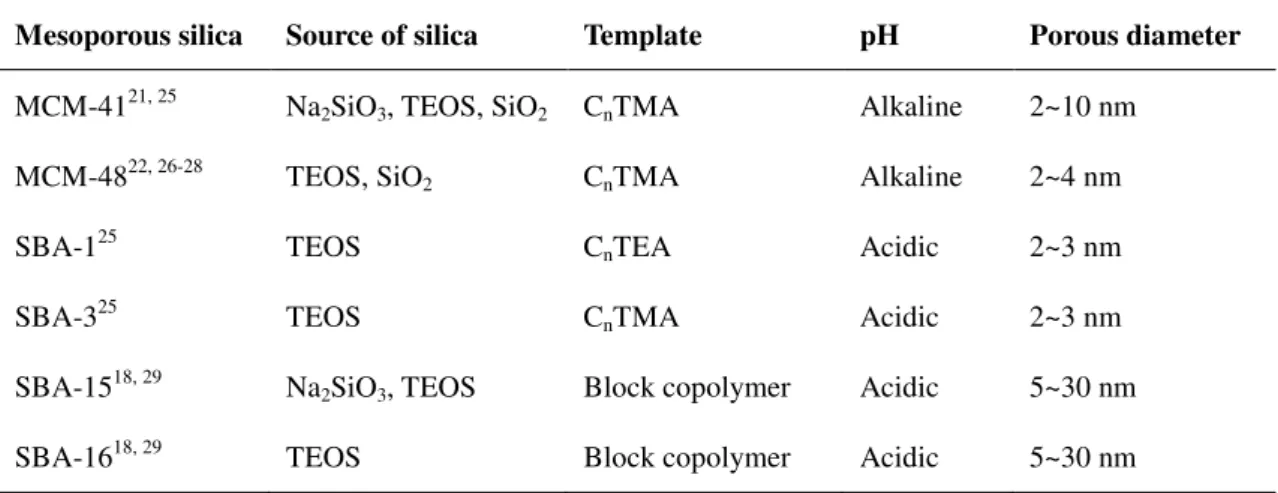
Table 3. Examples of some mesoporous silica with their synthesis source.24
Mesoporous silica Source of silica Template pH Porous diameter
MCM-4121, 25 Na
2SiO3, TEOS, SiO2 CnTMA Alkaline 2~10 nm
MCM-4822, 26-28 TEOS, SiO
2 CnTMA Alkaline 2~4 nm
SBA-125 TEOS CnTEA Acidic 2~3 nm
SBA-325 TEOS C
nTMA Acidic 2~3 nm
SBA-1518, 29 Na
2SiO3, TEOS Block copolymer Acidic 5~30 nm
SBA-1618, 29 TEOS Block copolymer Acidic 5~30 nm
In addition to the synthesis based on surfactant or block co-polymers (soft templates), there are also some synthesis methods based on hard templates, for example, carbon, resin, etc.30-36 Here, we mainly focusing on the soft template synthesis.
2.2.3.2 Synthesis methods
There are different methods for the synthesis of mesoporous materials:24 (1) room temperature synthesis,37, 38 (2) hydro-thermal synthesis,39 (3)
microwave-assisted synthesis,40, 41 (4) wet gel calcination,42 (5) phase transition,43, 44
(6) solvent evaporation method,45-48 (7) non-aqueous system synthesis, 49, 50 etc. The typical synthesis process consists of mixing the silica source (or other precursors) with the template (as structure-directing agent), followed by the aging or heating step, and the removal of the template by calcination or extraction (Figure 3).
There are several important factors that can influence the pore size. The most obvious factor is the type of template,18, 29 and even using the same type of template,
the pore size can be adjusted by the surfactant chain length (e.g. long-chain alkyltrimethylammonium halides).22, 51, 52 The synthesis temperature, time, pressure, pH, concentration, solvent, and additives can also control the morphology and structure of mesoporous materials.22, 29, 53, 54 The surface modification or thermal treatment with solvent after synthesis can improve the pores size control or the hydrothermal stability.55-57
2.2.4 Mechanism
2.2.4.1 The interaction between silica and template
In most of the synthesis approaches, the formation of mesoporous silica relies on the matching of charge at the silica-template interface.58 Different interactions (Figure
4) are possible: (a) the interaction between the silica anions (SiO-) and quaternary ammonium cations in basic environment; (b) the interaction between positive charged silica and cationic surfactant with the additional mediating halide ion X- in acidic environment; (c) the interaction between negatively charged silica and anionic surfactant with the additional mediating M+ cations in basic environment; (d) the interaction between positively charged silica and anionic surfactant in acidic environment; (e) the interaction between uncharged silica and nonionic surfactant via hydrogen bonds; (f) the interaction between silica ion pairs and nonionic surfactant via hydrogen bonds.25, 52
Since the discovery of MCM-41, people have proposed several different
mechanisms for the formation of the mesoporous structure, even though there is not a full understanding of its true essence of the mechanism until now. Here we introduce some of the most representative theories.
Figure 4. Interactions between the inorganic species and the head group of the surfactant with consideration of the possible synthetic pathway in acidic, basic, or
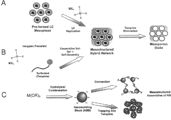
Figure 5. Main synthetic routes for the preparation of mesostructured materials.60
2.2.4.2 Liquid crystal templating
Figure 6. Powder X-ray diffraction patterns of (a) calcined cubic material and (b) the as-synthesized unstable lamellar material.22
In 1992, Beck et al.22 proposed the liquid crystal templating (LCT) mechanism.
During the synthesis and characterization of MCM-41, they found that the structure characterized either by microscopy or by X-ray diffraction were remarkably similar to that of liquid crystals or micellar phases formed in surfactant/ water systems (Figure
6). They proposed that the surfactant molecules self-assembled into liquid crystals were acting as templating agent, inside which the silicate precursors were penetrating and condensing forming the inorganic walls (Figure 5. A). They proposed also alternative pathways where the condensation of the silicate walls could possible occurs at different stages of the liquid crystal formation (Figure 7). The surfactant carbon chain length is a decisive factor to the size of the micelle as well as the size of the pores. The 13C-NMR spectrum of the as-synthesized MCM-41 also indicated the presence of quite similar phases between the surfactant in the pores and the liquid crystal, which means that the surfactant molecules arrange in a micellar array in the as-made MCM-41.
Figure 7. Possible mechanistic pathways for the formation of MCM-41: (1) liquid crystal phase initiated and (2) silicate anion initiated.22
2.2.4.3 Self-assembly and cooperative self-assembly
The cooperative mechanism (Figure 5. B) considers that the formation of
mesophase is the interaction between the acceleration of inorganic species condensation (caused by the existence of micelles) and the promotion of liquid crystal ordered arrangement (caused by the inorganic species condensation). These complicated interactions may contain, for example, electrostatic attractions, hydrogen bonds, and coordination bonds.
Figure 8 shows the model proposed by Davis.39, 61 The initial step is the formation of randomly ordered rod-like organic micelles; the second step yields tubes of silica surrounded micelles (two or three monolayers of tubular silica encapsulation), which occurs during the synthesis mixture when micelles interact with silicate species;
the third step is the spontaneous packing of randomly ordered composite species into hexagonal arrangement that produces the long-range in MCM-41; the fourth step is the further condensation of silicate species with heating. However, there is no complete condensation of silicate species because of the charge compensation between SiO- species and alkylammonium ions.
Figure 8. The mechanism proposed here for the formation of MCM-41.39
Figure 9 shows the model of Stucky.52, 62 The initial step is the formation of
organic and inorganic precursor solutions, the micelles can have different shapes (spherical, cylindrical or ellipsoidal) depending on the concentration of surfactant. After the mixing of organic and inorganic precursors, inorganic-organic aggregates appear with the ion exchange between silicate oligomers and Br-, OH- anions; the screening of electrostatic double-layer repulsion can induce self-assembly of silica tropic liquid crystalline mesophases. This model can explain the different phases obtained through variations of synthesis parameters (for example mixture composition and temperature), and the dynamic interplay among ion-pair inorganic and organic species was regarded as the decisive factor.
Based on the cooperative interaction mechanism, Stucky et al.25 developed the
generalized liquid crystal templating mechanism, which can be adapted to the synthesis of non-silicon-based ordered mesoporous materials as well. The cooperative charge matched templating, ligand-assisted templating, and neutral templating are the
three main models involved in this mechanism.
Figure 9. Schematic diagram of the cooperative organization of silicate-surfactant mesophases.62
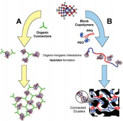
2.2.4.4 Nanometric building blocks
Figure 10. Different nanometric building blocks approaches involving clusters and different connectors.63
building blocks are formed by inorganic polymerization or precipitation reactions. By controlling these dynamic processes, the blocks can be assembled and linked to each other. The organic functions dangling on the particle surface or other organic connectors serve as linkages (Figure 5. C) .60
There are two main synthetic routes of nanometric building blocks approaches (Figure 10). One strategy is the Lego-like mesotextured hybrid materials built by the cross-linking hybrid moieties;64 the other strategy is the simultaneous process including hydrolysis-condensation and transalcoholysis reactions.65
2.2.4.5 Micellar structures
There are several different shapes of surfactant micelles, such as spheres,
cylinders, planar bilayers, reverse micelles, bicontinuous phases, liposomes, etc. (Figure 11),60, 66 which corresponds to a variation of the interfacial curvature.
Figure 11. Different shapes of micellar structures.60, 66
Figure 12. Formula of packing parameter g and schematic representation of amphiphilic molecules.60
Israelachvili et al.67, 68 proposed a simple model for micellar structures, which
can predict the mesophase with a packing parameter g (Figure 12). In this model, the surfactant is composed of a hydrophilic spherical head and a hydrophobic chain tail. In the packing parameter formula, V is the total volume (surfactant chains with
co-solvent/organic additive), lc is the fully extended surfactant tail length, and a0
is the effective head group area at the “micelles” surface.
With different g factors, different shapes of micellar structures can be obtained. (Table 4 and Figure 13)
Table 4. Packing parameter g of different micellar structures.60, 67, 68 g = v/lca0 Structures Examples
g < 0.33 spherical micelles single chain lipids with a large polar head (soaps or ionic detergents)
g = 0.33~0.5 cylindrical micelles single chain lipids with a small polar head (soaps or ionic detergents in
concentrated electrolyte solutions)
g = 0.5~1 bilayer (vesicles) double-chain lipids
g = 1~2 bilayer (membranes)
g = 2~3 inverse cylindrical micelles double-chain lipids and a small polar head
g > 3 inverse spherical micelles
Figure 13.Schematic representation of different g factors and the determinedmicellar
structures.69
understanding of synthesis mechanism and parameter control, we can do the design and the synthesis of mesoporous materials more purposeful and make the structures more predictable.
2.3 Modification and functionalization of mesoporous materials
Figure 14. Design of functionalized mesoporous materials for various catalyzed reactions.70
There are many different strategies to do the modification and incorporate new
functions in mesoporous materials. Depending on the different methods used for the functionalization, the position and local environment of functional groups or active sites are different (Figure 14). By direct synthesis, the functional groups can be inserted into the framework of the mesoporous structure; while by post synthesis, the functional groups can be grafted or coated on the surface of mesoporous materials. Due to the relatively large pore size and the high surface area, mesoporous materials have a great potential for the design and the exploitation of new catalysts. Figure 15 shows some examples of reactions catalyzed by functionalized mesoporous silica.71
Figure 15. Examples of reactions involved in the functionalization of mesoporous silica.71
2.3.1 Strategies
2.3.1.1 Direct synthesis
Figure 16. Insertion of organic function by direct synthesis using co-condensation of organosilanes (R represents the organic functional group).23
Direct synthesis of functionalized mesoporous silica is also called one-pot synthesis.72-75 For example, by con-condensation of (RO)
4Si, (R'O)3SiR, and
surfactant template, the organic functional groups can be anchored to the pore walls of mesoporous silica (Figure 16). The one-pot synthesis is very simple and in principle efficient. With this method, the functional groups are supposed to be homogeneously dispersed within the silica matrix, and there is no pore blocking. But the surfactant must be carefully removed without destroying the functional groups, and not all the active sites are accessible because some of the functional groups are dispersed into the framework of silica. Nonetheless, the inclusion of heterofunctions affects the structure of the silica matrix.
2.3.1.2 Post synthesis
The post-synthesis consists to modify chemically the already-made mesoporous
framework. The functional groups are incorporated on the surface of the mesoporous materials maintaining the ordered matrix skeleton. For example, the grafting of organosilanes (R'O)3SiR on the surface of the pores of a mesostructured silica (Figure
17). This method may lead to the decrease of pores diameter and to a non-homogeneous dispersion of the functional groups. However, the initial silica phase can be retained very well and the functional groups are more accessible as they are all loaded on the surface of the matrix.76
Figure 17. Post-synthesis by grafting organosilanes on the pore surface of mesoporous silica (R represent the organic functional group).23
In order to obtain the post-functionalized mesoporous materials, three main strategies can be applied: impregnation,77, 78 ion-exchange,79 and covalent
grafting.80-82 Within these methods, the functional groups have different interactions
with the matrix, and the location of the functional groups will be different as well.
2.3.1.3 Comparison of different methods
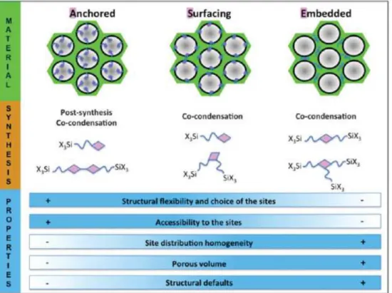
By using these different synthesis methods, the functional groups can be immobilized with different location, for example: anchored, surfacing and embedded. The requirement and preference for the location of the functional group should be guided by the application, then, implying the appropriate strategy. Several aspects should be considered, for example, the structural flexibility and choice of the sites, the accessibility to the sites, the sites distribution homogeneity, the porous volume, and the structural defaults. Figure 18 shows the comparison of the advantages and disadvantages of each type of functional groups.71
Figure 18. Comparison of different locations of the functional groups in the mesoporous silica.71
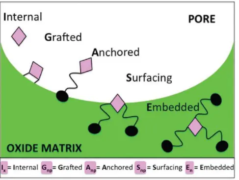
Figure 19. InGASE nomenclature for the location of a function in a porous solid.71
To describe the different location of immobilized functional groups, a new
nomenclature (InGASE) was proposed,71 which indicates the information of the
function location at the solid-fluid (gas or liquid) interface and the binding mode to the solid. Figure 19 shows the five types of possible function locations.
2.3.2 Functional groups category
Several different kinds of functional groups can be introduced on the
mesoporous silica surface, for example, organic functional groups, transition metal ions and oxide species, noble metal species, etc. They are incorporated as active sites to modify the solid properties.
2.3.2.1 Organic functional groups
When organic functional groups are introduced, the chemical properties of
mesoporous silica are modified, including the stability, hydrophilicity, hydrophobicity, pore size, surface silicon hydroxyl density, etc. Table 5 shows some examples of the organic functional groups commonly used in literature.
Table 5. Summary of common organic groups and their functions.
Organic groups Function
amino or aminopropyl
better accessibility for binding heavy metal species83, 84
enhanced absorptivity to acetaldehyde85
selective adsorption of dye pollutants86
selective binding of acidic gases87
diamino or triamino
adsorb chromate and arsenat88
CO2 capture89
ethylenediamine CO2 adsorption90
malonamide heterogeneous extraction of radionuclide91
carboxy protein immobilization92
thiol removing heavy metal ions from waste water81, 84
1-allyl mercury removal93
1-benzoyl-3-propylthiourea mercury removal94, 95
dithiocarbamate mercury removal96
imidazole selective adsorption of precious metal ions97, 98
saccharides boron removal99
2.3.2.2 Transition metals and oxide species
The transition metals and oxide species can be introduced on the surface of
mesoporous silica and work as catalytic active sites. There are a lot of reports about transition metallic catalysts supported on mesoporous silica (Table 6).
2.3.2.3 Noble metal species
By ion exchange, deposition-precipitation, impregnation, and some technique
such as vacuum evaporation, chemical vapor deposition, and super critical CO2
methods, the noble metal species can be incorporated onto mesoporous silica and they were widely used as catalysts in many reactions (Table 7).70
Table 6. Examples of transition metals and oxide species supported on mesoporous silica.
Metal Catalysis
Ti selective oxidation reactions, epoxidation reactions, etc.100-103
V oxidation reactions, oxidative dehydrogenation reactions, etc.104-106 Cu oxidation, epoxidation, hydroxylation reactions, etc. 107-110
Fe oxidation, epoxidation, hydroxylation reactions, etc.111-113
Mn oxidation reactions, epoxidation reactions, etc.114-116
Co oxidation reactions, photocatalysis, etc.117-119
Ni methanol reforming, hydrogenation reactions, etc.120-122
Al acidity, cracking reactions, etc.123-125
Table 7. Examples of noble metal catalysts and the method of preparation.126-142
Metal Preparation method Catalysis
Pt Inclusion in synthetic gel Vacuum evaporation Super critical CO2
Ion exchange to positively charged trimethylalkyl ammonium functionalized surface and reduction Ship-in-the-Bottle
CO oxidation
Water-gas shift reaction alkene hydrogenation
Ph (Rh-Pt) Super critical CO2 Butane hydrogenolysis to ethane
Au Ion exchange to trimethylalkyl ammonium functional group and reduction
Chemical vapor deposition
CO oxidation
Ru, Ru-Sn, Ru-Pt, Cu-Ru
Impregnation of carbonyl cluster together with organic counter cations
Hydrogenation
Pd Vapor phase diffusion-deposition Deposition-precipitation
Heck reaction Phenol hydrogenation Pd, Au Inclusion in synthetic gel/ incipient wetness CO oxidation
2.3.3 Fine control of functional groups
Figure 20. Controlled degradation of precursor for functional sites isolation.71, 143
Figure 22. Protection-deprotection method with bulky protecting groups.71, 147
The strategy of surface molecular engineering can be applied for the fine control
of the incorporation of functional groups on mesoporous silica to obtain well-defined active sites, with an appropriate environment and a better isolated state. There are several factors that we need to consider: the dispersion and the isolation of functional groups, the environment of functional groups, and the relative location of different functional groups, etc. The fine control at molecular level should not only be at short distance but also at long distance. Figures 20~22 show some examples of the approaches with different strategies.71
Surface organometallic chemistry (SOMC) approaches are widely used to control the grafting of organometallic complexes.148-152 Molecular stencil pattering
(MSP) technique can be applied to the synthesis of multifunctional materials.153-155
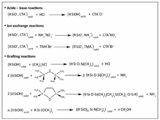
The main idea of the MSP technique is the partial coverage of functional groups. Figure 23 shows an example of this procedure: cetyltrimethylammonium (CTA+) or trimethyl ammonium (TMA+) can be used as molecular stencil because their cationic heads have electrostatic self-repulsion which make them regularly patterned on the surface of silica. The as made MCM-41 is washed with diluted HCl-ethanol solution to remove part of the surfactant so that the remained surface is available for the grafting of the first functional groups hexamethyldisilazane (HMDSA). Then, the residual surfactant is removed to make space for the following grafting of the second functional groups or active species. The role of HMDSA is to prepare isolated sites, thereby the second functional groups can be better dispersed. Besides HMDSA, several other organosilanes can be used as isolation sites to reduce the density of the site which is available for grafting, and they can also provide the hydrophobic surface of the silica, such as chlorotrimethylsilane (CTMS), 2,2,5,5-tetramethyl-2,5-disila-1-azacyclopentane, etc. Figure 24 shows the structure of some organosilanes that can be grafted on silica.
Figure 24. Examples of organosilanes that can be grafted on silica.71
2.3.4 Applications 2.3.3.1 Catalysis
Mesoporous silica is a very good candidate for the preparation of supported
heterogeneous catalysts own to its high surface area, relatively large pores diameter, narrow pores size distribution, various possibility for the modification of surface,
controllable hydrophilicity and hydrophobicity, etc. Inspired by biology science, the biomimetic catalysts are also a potential route for the design of mesoporous silicate catalysts. The catalysis applications of mesoporous materials include redox reactions, polymerization reactions, hydrogenation reactions, acid catalysis, base catalysis, halogenation reactions, photocatalysis, etc.156-158 We have summarized some examples of mesoporous silica supported metal catalysts in Table 6 and Table 7.
2.3.3.2 Adsorption and desorption
Table 8. Extraction of metal ions by different functionalized mesoporous materials.159
Mesoporous materials Functional groups Metal ion Adsorption capacity Detection limit Detection methods
Mesoporous silica Tetraacetamide derivative of cyclam Pb2+ 2.7×10⁻⁹ M Electroanalysis Mesoporous silica 3-Aminopropyl Cr5+ 4.35 mmol g-1 1.2 pg mL-1 AAS Mesoporous TiO2 V, Cr, Cu 1.1~6.3 pg mL-1 ETV-ICP-MS MCM-41 2,4-Dihydroxybenzaldehyde Be2+ 34 mg g-1 0.3 pg mL-1 ICP-OES Mesoporous Al2O3 As3+,Cr3+,As5+,Cr5+ 0.7~74 pg mL-1 ICP-MS MCM-41 Thiophene-2-carbaldehyde Pd2+ 5.0 mg g-1 0.2 ng mL-1 ICP-AES SBA-15 5-Mercapto-1-methyltetrazole Zn2+ 0.96±0.01 mmol g-1 8.0×10⁻⁹ M FAAS SBA-15 2-Mercaptopyrimidine Cd2+ 0.99±0.03 mmol g-1 FAAS Mesoporous silica Chitosan V, Cu, Pb, Cd, Hg 12.2~22.9 mg g-1 0.05~0.96 ng mL-1 ICP-OES MCM-41 5-Nitro-2-furaldehyde U5+, Th4+ 47~49 mg g-1 0.3 ng mL-1 ICP-OES Mesoporous TiO2 Dimercaptosuccinic acid As3+,Sb3+,As5+,Sb5+ 0.10~0.15 ng mL-1 ICP-OES Mesoporous silica 3-(2-Aminoethylami-no) propyl As3+, AS5+ 10.3 mg g-1 0.05 ng mL-1 ICP-OES SBA-15 Ethylenediamine Cd2+, Pb2+ 360±1.41±0.6 mgg-1 AAS
Ordered mesoporous materials are an ideal choice as adsorbents for polluted
water treatment. They present a high adsorption capacity, tunable surface functionalization, simple operation and recyclability. Table 8 gathers some examples of functionalized mesoporous materials and their corresponding adsorbable metal ions.160-172
Carbon dioxide capture and conversion is an important research topic as the
greenhouse effect and global warming arise more and more attention in the world. Mesoporous silica with organic amine functional groups is promising solid adsorbent of CO2 favorable for the rapid gas diffusion and easy regeneration. Several different
CO2 adsoption.173-176
Mesoporous silica modified with nickel, aluminium, or other functional groups can have a good hydrogen storage capacity,177-179 and are potentially suitable porous
materials for energy storage as well.
2.3.3.3 Sensors
Mesoporous silica is a promising material for developing electrochemical
sensors, gas sensors, and biosensors, which can be applied to the environment monitoring, optical detection, and food security control. Their high surface area, large porous volumes, and unique electronic properties are favorable for mass diffusion and sensible response to very low concentration target molecules. Figure 25 shows the advantages of porous silica materials for developing sensors. More information about mesoporous silica sensors can be found in several reviews.180-184
Figure 25. Advantages of porous silica materials for developing sensors.183
2.3.3.4 Biological and medical fields
Mesoporous silica nanoparticles (MSNs) are wildly used in the field of drug
carriers, protein and gene delivery, cancer therapy, etc. MSNs present a lot of advantages in medical applications as they have tunable size, shape, surface, and good
biocompatibility. The drug loading can be very high own to the high surface area (600~1000 m2/g) and pore volume (0.6~1.0 mL/g) of MSNs, and the targeted delivery
and release can be controlled by the surface functionalization of the silica. There are several factors that need to be considered for the design of MSNs for medical application, not only the characteristics of MSN, but also their behavior and interaction in the biological environment (cells, tissues, and circulation systems, etc), the toxicity, safety, and curative effects are very important. Figure 26 shows the considerations highlighted for the design mesoporous silica nanoparticles for biological and medical applications. Several groups have reviewed the progress of MSNs applications in biological and medical fields.185-189The development of new drugs based on mesoporous materials has great potential and it may open a door for the clinical therapy of some serious diseases.
Figure 26. The considerations highlighted for the design of mesoporous silica nanoparticles for biological and medical applications.185
2.4 Heterogeneous supported vanadium catalyst 2.4.1 Introduction
Vanadium (Z=23) is the twenty-second most abundant element in the earth crust
(0.013 % w/w).190 As very important strategic resources, it was wildly used in mechanical manufacturing, aerospace industry, steel and oil industry,architecture and transportation, chemistry and electrochemistry industry, nuclear fusion reactor, etc.191
Back to the 1870s, vanadium was used as the oxidation catalyst for the formation of aniline black from aniline. In 1895, vanadium oxide (V2O5) was used as the
catalyst for the oxidation of toluene and benzaldehyde.190 Nowadays, vanadium and
vanadium oxide compounds have become one of the most important oxidation catalysts in lots of industrial processes. Table 9 summarizes some industrial catalytic processes using vanadium oxides.192 Catalysts based on vanadium complexes, both homogeneous and heterogeneous, are wildly used in the oxidation of alkanes and alkylaromatics, epoxidation reactions, oxidation of alcohols, oxidative bromination reactions, oxidative strecker reactions, sulfoxidation, etc. Manas Sutradhar et al. have reviewed several oxidation reactions catalyzed by vanadium complexes in recent years.193, 194
Table 9. Industrial catalytic processes using vanadium oxides.195-201
Industrial process Catalyst material
Oxidation of SO2 to SO3 in the production of sulfuric acid V2O5
Oxidation of benzene to maleic anhydride V2O5
Oxidation of naphthalene to phthalic anhydride V, Mo oxides Oxidation of butene to phthalic anhydride V, P oxides Oxidation of o-xylene to phthalic anhydride V, Ti oxides Selective reduction of NOx with NH3 V2O5/ WO3/ TiO2
2.4.2 Vanadium incorporation in different supports
To improve the activity, selectivity, and mechanical strength of vanadium catalysts, vanadium oxide can be deposited on the surface of inorganic supports such as SiO2, TiO2, Al2O3, ZrO2, etc. Though the supports is normally considered as inert
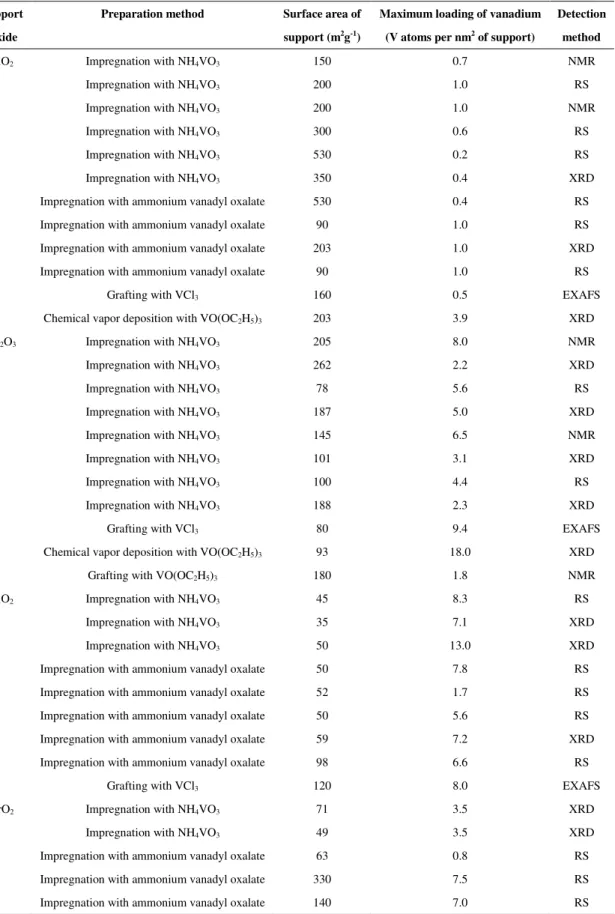
substance, there is an unclear interaction known as the metal oxide-support effect that contributes to the improvement of the catalyst performance. Table 10 summarizes some examples of vanadium oxide catalysts on different supports.192
Table 10. Different supports with different synthesis methods for the maximum vanadium oxide loading without formation of V2O5 crystals.192
Support Oxide
Preparation method Surface area of support (m2g-1)
Maximum loading of vanadium (V atoms per nm2 of support)
Detection method
SiO2 Impregnation with NH4VO3 150 0.7 NMR
Impregnation with NH4VO3 200 1.0 RS
Impregnation with NH4VO3 200 1.0 NMR
Impregnation with NH4VO3 300 0.6 RS
Impregnation with NH4VO3 530 0.2 RS
Impregnation with NH4VO3 350 0.4 XRD
Impregnation with ammonium vanadyl oxalate 530 0.4 RS
Impregnation with ammonium vanadyl oxalate 90 1.0 RS
Impregnation with ammonium vanadyl oxalate 203 1.0 XRD
Impregnation with ammonium vanadyl oxalate 90 1.0 RS
Grafting with VCl3 160 0.5 EXAFS
Chemical vapor deposition with VO(OC2H5)3 203 3.9 XRD
Al2O3 Impregnation with NH4VO3 205 8.0 NMR Impregnation with NH4VO3 262 2.2 XRD Impregnation with NH4VO3 78 5.6 RS Impregnation with NH4VO3 187 5.0 XRD Impregnation with NH4VO3 145 6.5 NMR Impregnation with NH4VO3 101 3.1 XRD Impregnation with NH4VO3 100 4.4 RS Impregnation with NH4VO3 188 2.3 XRD
Grafting with VCl3 80 9.4 EXAFS
Chemical vapor deposition with VO(OC2H5)3 93 18.0 XRD
Grafting with VO(OC2H5)3 180 1.8 NMR
TiO2 Impregnation with NH4VO3 45 8.3 RS
Impregnation with NH4VO3 35 7.1 XRD
Impregnation with NH4VO3 50 13.0 XRD
Impregnation with ammonium vanadyl oxalate 50 7.8 RS
Impregnation with ammonium vanadyl oxalate 52 1.7 RS
Impregnation with ammonium vanadyl oxalate 50 5.6 RS
Impregnation with ammonium vanadyl oxalate 59 7.2 XRD
Impregnation with ammonium vanadyl oxalate 98 6.6 RS
Grafting with VCl3 120 8.0 EXAFS
ZrO2 Impregnation with NH4VO3 71 3.5 XRD
Impregnation with NH4VO3 49 3.5 XRD
Impregnation with ammonium vanadyl oxalate 63 0.8 RS
Impregnation with ammonium vanadyl oxalate 330 7.5 RS
2.4.3 Preparation methods
There are several different methods to prepare the heterogeneous supported
vanadium catalysts, such as co-precipitation, impregnation,202-210 grafting,211-215 chemical vapor deposition (CVD),216-219 atomic layer deposition (ALD),220 thermal spreading,221, 222 etc. We have discussed the influence of the different strategies of
synthesis in chapter 2.3.1. For the incorporation of vanadium oxide active sites, it is important to have a good dispersion of the active sites and avoid the formation of V2O5 crystals. Table 10 summarizes some examples of different vanadium loading
limits on different supports with different synthesis methods. As we have discussed in chapter 2.3.3, with the assistance of organic functional groups, the fine control of the surface active sites dispersion would be a potential strategy to develop high performance supported vanadium catalysts.
2.4.4 Vanadium species and structures
Vanadium was named vanadin by Sefström, this is from the name of Nordic
goddess Vanadis, who symbolises beauty and fertility,190 which are also the features of vanadium chemistry. Vanadium compounds have different beautiful colors depending on the oxidation states of vanadium. The electron configuration of vanadium is [Ar]3d34s2, taking the reduction of NH4VO3 as an example, V5+ (d0) species show a
yellow color, V4+ (d1) species show a blue color, V3+ (d2) species show a green color, while V2+ (d3) species show a violet color.223 The easily interconvertible vanadium oxidation states and their high affinity to oxygen encourage the application of vanadium catalysts for oxidation reactions.
V5+ and V4+ are the most common and stable states. There are three main coordination states of V5+: tetrahedral (VO4), pentahedral (VO5) and octahedral (VO6).
In the solid state, V2O5 is an acidic oxide with the orange-red color, each vanadium
oxide unit has an octahedrally coordinated VO6. By mild reduction of V2O5, a dark
blue amphoteric oxide VO2 can be obtained. However, in aqueous it is more
complicated, depending on the vanadium concentration and the solution pH, different vanadium oxide species can be observed. Figure 27 shows the different stable
vanadium species that can exist in aqueous solutions with different pH and vanadium oxide concentrations.192
Figure 27. Pourbaix diagram of vanadium (temperature: 25 ◦C, ionic strength: 1M).192
The supported vanadium oxides are quite different from the unsupported ones on their chemical and electronic properties. Taking the impregnation of NH4VO3 as an
example, after the drying and calcination steps, the vanadium oxide compound can be chemically anchored onto the surface of the support (Figure 28).192
Figure 28. Synthesis of a supported vanadium oxide catalyst by impregnation of a NH4VO3 solution followed by calcination in the presence of oxygen.192
Even by different synthesis methods, or on different oxide supports, after calcination, the supported vanadium oxide catalysts are found to have the same vanadium oxide configurations.195, 197, 224, 225 During the heating procedure, the
adsorbed water molecules are removed, and by the esterification reaction, the oxidized V5+ compound can be anchored through the hydroxyl groups on the support. The resulting species possesses essentially the same local coordination environment as supported vanadium oxides. The isolated VO4 units (symmetry C3v) with one
terminal mono-oxo V=O bond (~1.62 Å) and three bridging V-O-Support bonds (~1.81 Å) are formed at low loading of vanadium (Figure 29 a).192, 226 For high loading of vanadium, dimeric and polymeric chains of VO4 units can be formed (with
one V-O-Support bond, two bridging V-O-V bonds, and a terminal V=O bond) (Figure 29 b).
Figure 29. Three types of V-O bonds in monomeric and polymeric VO4 species.192
The different dispersion states of vanadium oxides on the supports may include several molecular configurations: isolated vanadium ions (Figure 30 a), dimeric species (Figure 30 b), polymeric species, two-dimensional over-layer built up by chains of vanadium ions (Figure 30 c), three-dimensional vanadium oxides, V2O5
crystals (Figure 30 d) and mixed metal oxide phases with the support. The available surface area and surface hydroxyl groups are two important factors for the formation of different aggregation states of surface vanadium species. High surface area usually means more hydroxyl groups, which are favorable for a better dispersion of isolated vanadium oxide species.192