HAL Id: hal-01394665
https://hal.inria.fr/hal-01394665
Submitted on 21 Dec 2016
HAL is a multi-disciplinary open access
archive for the deposit and dissemination of
sci-entific research documents, whether they are
pub-lished or not. The documents may come from
teaching and research institutions in France or
abroad, or from public or private research centers.
L’archive ouverte pluridisciplinaire HAL, est
destinée au dépôt et à la diffusion de documents
scientifiques de niveau recherche, publiés ou non,
émanant des établissements d’enseignement et de
recherche français ou étrangers, des laboratoires
publics ou privés.
Natural Interpretation of UML/MARTE Diagrams for
System Requirements Specification
Aamir Mehmood Khan, Frédéric Mallet, Rashid Muhammad
To cite this version:
Aamir Mehmood Khan, Frédéric Mallet, Rashid Muhammad.
Natural Interpretation of
UML/MARTE Diagrams for System Requirements Specification.
2016 11th IEEE
Sympo-sium on Industrial Embedded Systems (SIES), May 2016, Krakow, Poland.
pp.193-198,
Natural Interpretation of UML/MARTE Diagrams
for System Requirements Specification
Aamir M. Khan
Dept. of Electrical & Computer Engg. College of Engineering, University of Buraimi, Oman.
Aamir.m@uob.edu.om
Fr´ed´eric Mallet
Universit´e Nice Sophia Antipolis I3S, UMR 7271 CNRS, INRIA
Sophia Antipolis, France Frederic.Mallet@unice.fr
Muhammad Rashid
Dept. of Computer Engg., College of Computer & Info. Systems, Umm Al-Qura University, Saudi Arabia.
mfelahi@uqu.edu.sa
Abstract—To verify embedded systems early in the design stages, we need formal ways to requirements specification which can be as close as possible to natural language interpretation, away from the lower ESL/RTL levels. This paper proposes to contribute to the FSL (Formal Specification Level) by specify-ing natural language requirements graphically in the form of temporal patterns. Standard modeling artifacts like UML and
MARTE are used to provide formal semantics of these graphical models allowing to eliminate ambiguity in specifications and automatic design verification at different abstraction levels using these patterns.
Keywords—Graphical Properties, Temporal Patterns,FSL,UML,
MARTE, CCSL, LTL, Modeling, Embedded Systems
I. INTRODUCTION
To verify embedded systems we need to specify system requirements formally. Requirements expressed in natural lan-guage are ambiguous and the ones expressed in lower levels like electronic system level (ESL) cannot deal with design com-plexity. Intermediate levels like the Formal Specification Level (FSL) [1] have been proposed to fill this gap with models that are both close enough to requirements engineer concerns, and formal enough to allow further phases of automatic or semi-automatic generation and verification. This paper contributes to this effort at FSL.
To express our requirements, we want to use formal but natural graphical representation of systems for which we propose to use UML (Unified Modeling Language) [2] and its extensions. We use MARTEprofile [3] to extendUML to build timed and untimed requirements for real-time and embed-ded systems. Additionally, the Clock Constraint Specification Language (CCSL) [4] is used to complement UML/MARTE
modeling elements with timed or causal extensions which is important to keep the requirements formal and executable.
This paper proposes graphical properties to represent var-ious temporal patterns that occur frequently in systems. We studied various case studies like the stream boiler [5], railway interlocking system [6] and the traffic light controller [7] to extract recurring temporal patterns. To express these temporal artifacts in UML, we need MARTE time model and the as-sociated CCSL. The expressiveness of MARTE/CCSL alone is not enough to model such graphical patterns, so we propose
Partially funded by the National Science, Technology, and Innovation Plan (NSTIP) Saudi Arabia.
an extension to the UML in the form of Observation profile. Stereotypes from this profile are then used to build scenarios, basic building block for the graphical patterns. Moreover, set of rules are defined for creating such patterns. To model temporal behavior, a library of frequently occurring patterns is presented usingUMLstate machine diagrams. Stereotypes from the MARTEtime model are used to express logical clocks and time units. Presented approach in this paper finds its worth by three characteristics that are not, to the best of our knowledge, used jointly in previous approaches. (1) A set of predefined primitive domain-specific property patterns, (2) A graphical
UML/MARTEformalism to capture the properties. Rather than having to rely on natural-language, the semantics of these graphical properties is given by a MARTE/CCSLspecification, (3) Logical polychronous time [8] as a central powerful abstraction to capture both causal and temporal constraints.
Rest of the paper discusses the related work (section II) followed by UML/MARTE semantics (section III) and the introduction of Observation profile (section IV). Then we present the temporal patterns as major contribution of the paper (section V) which are then applied to a traffic light controller case study (sectionVI). Finally sectionVIIconcludes the paper with a glimpse over the future possibilities.
II. RELATEDWORK
Various efforts have been made over the past two decades to bridge the gap between natural language and temporal logic. Initially Dwyer proposed property specification patterns [9] in the form of a library of predefinedLTL(linear temporal logic) formulae from where the users can pick their desired pattern to express the behavior. Most works on such algorithms focus on LTL/CTL[10] for expressing the temporal constraints [11] where high expertise is required to correctly capture the properties to be verified.
Various related work propose the specification ofLTL/CTL
temporal properties through graphical formalisms. Property Se-quence Charts (PSC) [12] are presented as an extension toUML
sequence diagrams to model well-known property specification patterns. Later extension in the form of Timed PSC [13] also supports the specification of timing requirements. Work by Bellini [14] presents a logic language, TILCO-X, which can be used to specify temporal constraints on intervals, again based on LTL. The work of Konrad [15] is to express real-time properties with a facility to denote real-time-based constraints
Full text available on IEEE explorer:
in real-time temporal logic MTL (Metric Temporal Logic) extending LTL. Finally the research work, DDPSL (Drag and DropPSL) [16], presents a template library definingPSLformal properties using logical and temporal operators. The research community of runtime verification [17] relies on lightweight formal verification techniques based on LTL/CTL. It check the
correctness of the behavior of a system with the focus on generation of efficient observers for online monitoring. As opposed to this, our proposed framework targets the integration of observers in a complete work-flow. The focus here is on the presenting a natural way to model temporal behavior.
We also promote the use of graphical models over the use of temporal logic formula. Indeed, while temporal logic like LTL/CTL, are widely used in the later design stages in conjunction with model-checkers [18], they are not suitable to directly express high-level requirements at early stages. They are commonly rejected by requirements engineers [19] despite the various attempts to alleviate the syntax with higher-level constructs like in PSL(Property Specification Language) [20]. So we endorse to loose the expressiveness of LTL if we have a clear and formal graphical way of defining properties. Moreover, the domain of expressiveness of CCSL(used in our approach) is different fromLTLandLTL-based languages (like
PSL) [21]. Here we are interested to express properties on logical clocks for which LTL is not an obvious choice. Also
LTLis not meant to express physical time properties, for which, this framework prefer the use ofCCSL. Moreover,PSCs do not benefit from the popular embedded systems modeling and anal-ysis profiles like MARTE. Rather than encoding formula with
UMLextensions, we propose to reuse UML/MARTE constructs to build a set of pre-defined property patterns pertinent for the domain addressed.
Another aspect of the related work is the advent of Formal Specification Level (FSL), still an informal level of represen-tation. The focus of the FSL approach is to transform natural language descriptions directly into models bridging the design gap. On the other hand, our proposed framework targets the graphical representation of temporal properties replacing the need for textual specification of the system. Natural language front-end is a general trend to allow for a syntax-directed translation of concrete pattern instances to formulae of a temporal logic of choice, also used in [15]. Our framework approach is different from the FSL approach as we target
the verification and validation of a subset of behavior rather than the complete system. Design engineers are usually well acquainted to UML diagrams and any graphical alternative to complexCCSLorLTL/CTLnotations is more likely to get wide acceptance. Moreover, the use ofMARTEprofile allows to reuse the concepts of time and clocks to model timing requirements of embedded systems.
III. UML/MARTESEMANTICS
This paper proposes an approach to interpret the UML
diagrams in a natural way. Hence this section introducesUML
state of the art. UML itself lacks the notion of time which is essentially required in modeling temporal patterns. So selected features from the MARTEtime model are explained which are used to facilitate semantically sound representation of time.
A. UMLState of the Art
UML state machine diagrams [22] provide a standardized way to model functional behavior of state-based systems. They provide behavior to an instance of a class (or object). Each state machine diagram basically consists of states an object can occupy and the transitions which make the object change from one state to another according to a set of well defined rules. Transitions are marked by guard conditions and an optional action. Among the set of state machine elements defined, only a small subset is used by the presented approach to represent graphical properties by giving specific semantics to that chosen subset. The presented approach specifies S as a set of finite states consisting of simple states and final states while the other states (like initial pseudo-states and choice pseudo-states) are not used at all. From the standard set of state machine elements, only the top region is used while all other set of regions like in state hierarchy are not considered. Finally, the state machine is considered to have a finite set of valid transitions.
B. MARTE Time Model
The proposed approach uses concepts of clocks and time for which MARTE time model [3] is utilized. MARTE time model provides a sufficiently expressive structure to represent time requirements of embedded systems. In MARTE, time can
be physical, considered as dense or discrete. But it can also be logical and related to user-defined clocks. Time may even be multiform, allowing different times to progress in a non-uniform fashion, and possibly independently to any (direct) ref-erence to physical time. At the heart of the MARTETime sub-profile, the stereotype ClockType extends the metaclass Class while the stereotype Clock extends metaclasses InstanceSpeci-ficationand Property. Clocks can appear in structural diagrams (like SysML block definition or UML composite structure) to represent a family of possible behaviors. This clock association gives an ability to the model elements identifying precisely instants or duration.
IV. OBSERVATIONPROFILE
The combined features ofUMLandMARTEprovide a base for developing timed-models but they still lack the specialized features to model graphical temporal patterns. This section presents the first contribution of this paper in the form of a
UML profile extension targeting temporal patterns. We intro-duce the Observation profile which is designed to target the expressiveness of graphical temporal properties. This profile resides on top of the UML/MARTE to provide a structure for building some predefined patterns. The focus of the presented work is not the minimalist approach but rather the expres-siveness of the property from the system designer’s point-of-view. So when a property specifies occurrence of something at some point in time, then it is an event and it seems natural to represent such properties as logical clocks. But when the properties specify duration or interval (not a particular point in time), then the obvious choice of representation is state relations.
In the proposed approach, extended state machine diagrams are mainly used to represent the behavior patterns of a system. These diagrams provide a more natural and syntactically
sound interpretation of graphical behavioral patterns of system states. State machines are used to model state-based relations represented graphically in the form of scenarios. Two basic scenarios are possible: negative and positive. These scenarios act as building blocks for more complex state patterns.
Fig. 1: Positive and Negative Scenarios
Positive scenariosmodel something that must happen un-der given conditions, as shown in Figure 1. Two types of stereotypes are used in this scenario. The ObservationSce-nario stereotype extends the UML state machine metaclass. It defines further three tagged values: ScenarioType, Consider and Ignore. ScenarioType is the basic type of the scenario. Consider contains the collection of all the events that are relevant to this scenario. It is just like the sensitivity list in SystemC, Verilog or VHDL. If the list of relevant events is large, then the list of events that are not relevant maybe modeled using the Ignore. Another stereotype applied to the scenario is the ActivationState stereotype. It extends the UML
state metaclass and is used to identify the state that activates this particular scenario. It is active whenever the system is in a specific condition. The positive scenario expects an event to occur whenever the considered state is active. Failure occurs if the event does not occur. The scenario terminates normally if the desired event occurs. In Figure 1, the positive scenario represents the relation State A starts State B. Hence one state is ensuring to start another state at the same time, which is a very common behavior in systems.
Negative scenariosmodel something that must not happen under given circumstances. So when the state machine is active, it checks for a particular trigger event that leads the system to a violation/error state shown in Figure 1. This type of properties can use model-checking to detect if the system under observation ever reaches an error state. The negative property in the figure models the relation State A excludes Event e, which means the event e is not possible while the state is A. One other stereotype applied optionally to the states is the Duration stereotype used to model delay in some cases of temporal patterns (not shown here). It also extends the
UMLstate metaclass. Figure 2 shows the proposed Observation profile as a collection of all these presented stereotypes.
V. PROPOSEDTEMPORALPATTERNS
The major contribution of this proposed approach is to provide a set of reusable generic graphical temporal patterns. For identifying the temporal properties of systems, we started
Fig. 2: Proposed Observation Profile
by considering several examples like the stream boiler case study [5], railway interlocking system [6] and the traffic light controller case study [7]. Working on these diverse examples to model behavioral properties in UML, we extracted several recurring temporal patterns. These patterns collected across various examples were refined with some inspiration taken from the Allen’s algebra targeting intervals [23]. This practice gave us a valuable collection of generic patterns divided into three major categories of behavioral relations that may exist in a system: state-state relations, state-event relations, and event-event relations. Researchers have already shown that constraints specified in CCSL are capable of modeling logical event-event temporal relations [24]. These CCSL constraints can be represented graphically using SysML/MARTE mod-els [25]. Temporal patterns for the other two categories of relations are:
State-State Relations: precedes, triggers, contains, starts, finishes, implies, forbids, and excludes.
State-Event Relations: excludes, triggers, forbids, con-tains and terminates.
Next subsections discuss selected few of these temporal patterns. These patterns with their syntax and semantics are discussed in detail in an online report [26].
A. State-State Relations
Presented approach including the two basic scenarios can be used to formally model relations between two different states of a system. Allen’s algebra [23] for intervals provides a base defining thirteen distinct, exhaustive and qualitative relations of two time intervals. From the comparative analysis of these relations, six primitive relations are extracted that can be applied to the state-based systems. Further two ‘negation’ relations are added (forbids, excludes), based on their usage and importance in the examples, to complete the set.
Semantically a state can be considered similar to an inter-val. We use the nomenclature of using capital letters (A,B,...) to denote states and small letters (a,b,...) for events/clocks. Dot notation like SM1.turnA is also used throughout the text to show the specific events. Given a strict partial ordering
S “ xS, ăy, a state in S is a pair ras, afs such that as, af P
S and asă af. Where as is the start and af is the end of the
state interval. An event or point e belongs to a state interval ras, afs if asď e ď af (both ends included).
Precedence is an important state property where the rela-tion ‘A precedes B’ means the state A comes before the state
B. It includes a delay/deadline clause to explicitly specify the duration between the termination of state A and the start of state B. Use of precedence relation with specific delay can also be equated to the triggers state-event relation (e triggers A after [m,n] on clk). The unit of the duration is dependent on the level of abstraction that is target of the graphical specification, i.e., it can be physical clock, loosely timed clock, or logical clock. Deadline defers the evaluation of state A until some number of ticks of clk (or any other event) occur. The number of ticks of clk considered are dependent on the two parameter natural numbers min and max evaluated as:
‚ [0, n] means ‘before n’ ticks of clk ‚ [m, 0] means ‘after m’ ticks of clk ‚ [m, m] means ‘exactly m’ ticks of clk
Mathematically, given a partial ordering S having the states A (ras, afs) and B (rbs, bfs), a constant n and a clock clk, the
equation
A ď B by rm, ns on clk
means af ď bs and bsoccurs within the duration af` ∆,
where ∆ is between m and n ticks of event clk. The last tick of clk coincides with the start the state B (i.e, bs). Graphically,
precedence is based on positive scenarios shown in Figure 3. The first state (State is A) is an activation state (shown by the stereotype) while the second state has the duration stereotype applied to specify the interval. The observation scenario gets active when the state machine SM1 gets in A state. It then checks for the state exit (turnNotA) and expects the other state machine SM2 to be in state B within the specified time duration. If this behavior occurs as desired, then the scenario goes dormant till the next state activation occurs.
Fig. 3: Aprecedes Bby[2, 4]onclk
Forbiddance is a negation property. Relation ‘A forbids B’ bars B to occur after state A occurs. It has another slightly different operator that works with events (e forbids A), discussed later on. Hence mathematically, given a partial ordering S having the states A (ras, afs) and B (rbs, bfs), the
equation A B means bs ‰ af. Its graphical temporal
pattern is shown in Figure 4. Scenario activates whenever SM1 is in state A and on exiting this state, the SM2 is expected to be not in state B (else violation occurs).
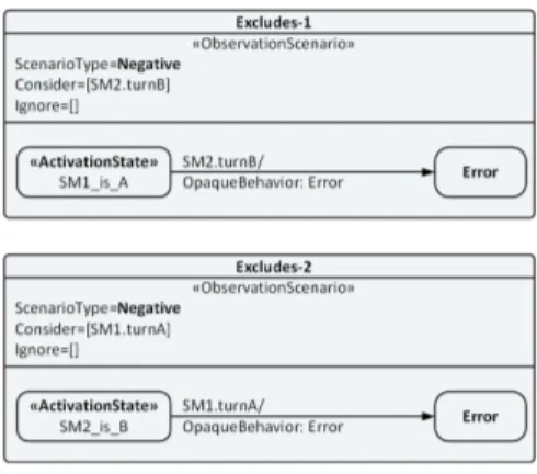
Exclusion between two states restricts them to occur at the same time. Mathematically, given a partial ordering S having the states A (ras, afs) and B (rbs, bfs), the relation ‘A excludes
B’ means that bf ă as or af ă bsfor all instances of A and
B. This relation can be decomposed into two basic state-event exclusion relations (shown without boxed symbols).
Fig. 4: AforbidsB
A # bs and B # as
Graphically, this temporal pattern is derived from the exclusion relation of state and event (discussed in the next sub-section). Two negative scenarios are used to model this behavior as shown in Figure 5. So during the particular state A for SM1, the event turnB is expected not to occur and vice versa for the other case.
Fig. 5: AexcludesB
B. State-Event Relations
The relations between the system states and events can be modeled using the UML sequence diagrams or state machine diagrams. Here in this text we will only focus on the state machine based patterns. Based on the use, we discuss two state-event relations here.
The excludes relation state A excludes event e is a bijective relation. Mathematically, given a partial ordering S having the state A (ras, afs) and a clock e, it can be expressed as A # e
where e R ras, afs. It implies either e ă as or af ă e.
Graphically it is modeled using a negative scenario, as shown in Figure 6. Here the SM1 while in state A, will cause error on event e.
The terminates relation is similar to finishes relation for states. The relation event e terminates state A can be expressed mathematically, given a partial ordering S having the state A (ras, afs), an event e, a constant n and a clock clk, as
e ) A af ter rm, ns on clk
It means af occurs within the duration e ` ∆, where
∆ is between m and n ticks of event clk. Graphically, it is implemented using the positive scenario state machine, as shown in Figure 7.
Fig. 7: eterminates Aafter[3,7]onclk
VI. APPLICATION OFTEMPORALPATTERNS
Utility of temporal patterns is shown through a case study of traffic light controller taken from SystemVerilog Assertions Handbook [7]. It consists of a cross-road over North-South highway and the East-West farm road. There are sensors installed for the emergency vehicles and for the farm road traffic. Highway traffic is only interrupted if there is a vehicle detected by the farm road sensor. The architecture for the traffic light controller consists of two state machines, interface signals of the module and the timers. A few temporal verification properties of the design are discussed next.
Fig. 8: ns light=GREENexcludes ew light=GREEN
Safety property, Never NS/EW lights both GREEN
simultaneously. This property is the exclusion of two states ns light.GREEN and ew light.GREEN. From our library of graphical temporal patterns, we consider two state-event ex-cludes temporal patterns as shown in Figure 8. Here if ns light is GREEN is the activation state from SM1, then in the generic pattern we replace the event e with the start event of the opposite signal (turnGREENof ew light).
State of lights at reset. This constraint requires that whenever reset occurs, the ns light turns off. This property
Fig. 9: reset=ACTIVE impliesns light=OFF
shows that ns light.OFFis the consequence of reset. From our library of graphical properties, we use the implies operator for the relation, shown in Figure 9. The implies relation is like the excludes state-state relation as it is further composed of two state-state relations: starts and finishes. The starts relation guards the beginning of implies relation while the finishes guards the end of the implication relation. Both the relations are implemented using positive scenarios.
Fig. 10: ns light=YELLOWprecedes ns light=RED
Safety, GREEN to RED is illegal. Need YELLOW. This constraint is an example of the difference between the textual specification and the constraint implemented as assertion. Though theYELLOWstate is specified in the text but it is never tested in the actual SystemVerilog assertion. Here the graphical approach is clear and precise in using the precedes relation for states (without defining any delay), shown in Figure 10. Here the name of the state ‘ns light is not YELLOW’ is not required (as it is not an activation state), and any desired name can be used. The property here ensures YELLOWcomes before RED. To avoid cases like YELLOW ñ GREEN ñ
RED, we can add another constraint ns light=GREENprecedes ns light=YELLOW. A little varying intent can also be im-plemented using the forbids relation ns light=GREENforbids ns light=RED which seems to be the desired one for the text ‘green to red is illegal’.
Verification: Graphical interpretation of properties are im-plemented in the form of observers. Verification by observers is a technique widely used in property checking [27]. They check the programs for the property to hold or to detect anomalies. In the presented framework, each temporal pattern is finally transformed into a unique observer code for a specific abstraction level (like register transfer level -RTL). It proposes to create a library of verification components for each graphical temporal pattern. An observer provides implementation to the semantically sound graphical patterns. An observer consists of a set of input parameters, one for each activation state and
event. A special violation output is there to flag any anomaly in the behavior. The way these patterns work is by relying on adapters as a glue logic. These adapters convert the signal or group of signals from the system to states and events. The property patterns implemented in the framework use these events and states. So adapters come in-between the module under verification and the observers. They receive inputs in the form of design module interface signals and state values. From this they generate the appropriate logical clock outputs and state identifiers to be consumed by the observers.
VII. CONCLUSION ANDFUTUREWORK
This paper presents a natural way to interpret UML dia-grams annotated with features from MARTEto specify system requirements. It proposes a graphical approach to capture properties in a bid to replace temporal logic properties like in
LTL. It also proposes a way to extend the existing capabilities of CCSL which can though represent state relations but is not practically meant for that task. The proposed approach identifies two major categories of temporal patterns, state-based and mixed state/event relations. Semantics of the states in both types of properties have been expressed as state-start and state-end events. An exhaustive set of state relations, based on Allen’s work, have been proposed. Later these relations are implemented using a subset of state machine diagrams and sequence diagrams coupled with features from MARTE time model and Observation profile.
In the future, we wish to extend this work as a complete framework providing a comparative analysis of the presented operators with that of existing CCSL operators and code generation from the graphical properties. In regards to this continued effort, a tool plugin has been developed [28] for model transformation of such graphical patterns directly into
CCSL and VerilogHDL based observers. ACKNOWLEDGMENT
This project is partially funded byNSTIP(National Science Technology and Innovative Plan), Saudi Arabia under the Track “Software Engineering and Innovated Systems” bearing the project code “13-INF761-10”.
REFERENCES
[1] M. Soeken and R. Drechsler, Formal Specification Level - Concepts, Methods, and Algorithms. Springer, 2015. [Online]. Available: http://dx.doi.org/10.1007/978-3-319-08699-6
[2] J. Rumbaugh, I. Jacobson, and G. Booch, Eds., The Unified Modeling Language Reference Manual. Essex, UK, UK: Addison-Wesley Longman Ltd., 1999.
[3] Object Management Group, Time Modeling in UML Profile for MARTE: Modeling and Analysis of Real-time Embedded Systems, Object Management Group (OMG) Std. version 1.1, 2011. [Online]. Available: http://www.omg.org/spec/MARTE/
[4] C. Andr´e, “Syntax and Semantics of the Clock Constraint Specification Language (CCSL),” INRIA, Research Report RR-6925, 2009. [Online]. Available: https://hal.inria.fr/inria-00384077
[5] M. Al-Lail, W. Sun, and R. B. France, “Analyzing Behavioral Aspects of UML Design Class Models against Temporal Properties,” in Quality Software (QSIC), 2014 14th International Conference on, Oct 2014, pp. 196–201.
[6] A. E. Haxthausen, “Automated generation of formal safety conditions from railway interlocking tables,” Int. J. Softw. Tools Technol. Transf., vol. 16, no. 6, pp. 713–726, Nov. 2014.
[7] B. Cohen, S. Venkataramanan, A. Kumari, and L. Piper, SystemVerilog Assertions Handbook: for Dynamic and Formal Verification, 2nd ed. Palos Verdes Peninsula, CA, USA: VhdlCohen Publishing, 2010. [8] P. L. Guernic, T. Gautier, J. Talpin, and L. Besnard, “Polychronous
automata,” in 2015 International Symposium on Theoretical Aspects of Software Engineering, TASE 2015. IEEE Computer Society, 2015, pp. 95–102. [Online]. Available: http://dx.doi.org/10.1109/TASE.2015.21 [9] M. B. Dwyer, G. S. Avrunin, and J. C. Corbett, “Patterns in
property specifications for finite-state verification,” ser. ICSE ’99. New York, NY, USA: ACM, 1999, pp. 411–420. [Online]. Available: http://doi.acm.org/10.1145/302405.302672
[10] A. Pnueli, “The Temporal Logic of Programs,” in 18th Annual Sympo-sium on Foundations of Computer Science. IEEE Computer Society, 1977, pp. 46–57.
[11] A. Bauer, M. Leucker, and C. Schallhart, “Runtime Verification for LTL and TLTL,” ACM Trans. Softw. Eng. Methodol., vol. 20, no. 4, pp. 14:1–14:64, Sep. 2011. [Online]. Available: http://doi.acm.org/10.1145/2000799.2000800
[12] M. Autili and P. Pelliccione, “Towards a graphical tool for refining user to system requirements,” Electron. Notes Theor. Comput. Sci., vol. 211, pp. 147–157, Apr. 2008. [Online]. Available: http://dx.doi.org/10.1016/j.entcs.2008.04.037
[13] P. Zhang, B. Li, and L. Grunske, “Timed Property Sequence Chart,” J. Syst. Softw., vol. 83, no. 3, pp. 371–390, Mar. 2010. [Online]. Available: http://dx.doi.org/10.1016/j.jss.2009.09.013
[14] P. Bellini and P. Nesi, “Tilco-x, an extension of tilco temporal logic,” in ICECCS’2001, 2001, pp. 15–25.
[15] S. Konrad and B. H. C. Cheng, “Real-time Specification Patterns,” in ICSE ’05. New York, NY, USA: ACM, 2005, pp. 372–381. [16] L. Di Guglielmo, F. Fummi, N. Orlandi, and G. Pravadelli, “DDPSL:
An easy way of defining properties,” in Computer Design (ICCD), 2010 IEEE International Conference on, Oct 2010, pp. 468–473.
[17] M. Leucker and C. Schallhart, “A brief account of runtime verification,” The Journal of Logic and Algebraic Programming, vol. 78, no. 5, pp. 293 – 303, 2009.
[18] E. Clarke, O. Grumberg, and D. Peled, Model Checking. MIT Press, 1999. [Online]. Available: https://books.google.com.om/books?id=Nmc4wEaLXFEC
[19] M. Chai and B.-H. Schlingloff, Runtime Verification: 5th International Conference, RV 2014, Toronto, ON, Canada, September 22-25, 2014. Proceedings. Cham: Springer International Publishing, 2014, ch. Monitoring Systems with Extended Live Sequence Charts, pp. 48–63. [20] IEEE, “Property Specification Language (PSL),” IEEE, 2010. [Online].
Available: http://standards.ieee.org/findstds/standard/1850-2010.html [21] R. Gascon, F. Mallet, and J. Deantoni, “Logical Time and Temporal
Logics: Comparing UML MARTE/CCSL and PSL,” ser. TIME ’11. Washington, DC, USA: IEEE Computer Society, 2011, pp. 141–148. [Online]. Available: http://dx.doi.org/10.1109/TIME.2011.10
[22] Object Management Group (OMG), “Unified Modeling Language (UML), Superstructure Specification, Version 2.4,” 2011.
[23] J. F. Allen, “Maintaining knowledge about temporal intervals,” Commun. ACM, vol. 26, no. 11, pp. 832–843, Nov. 1983. [Online]. Available: http://doi.acm.org/10.1145/182.358434
[24] C. Andr´e, F. Mallet, and R. de Simone, “Modeling time(s),” in Model Driven Engineering Languages and Systems, ser. Lecture Notes in Computer Science. Springer Berlin Heidelberg, 2007, vol. 4735. [25] F. Mallet, Formal Modeling and Verification of Cyber-Physical Systems,
September 2015, ch. MARTE/CCSL for Modeling Cyber-Physical Systems, pp. 26–49.
[26] A. M. Khan, F. Mallet, and M. Rashid, “Natural Interpretation of UML/MARTE Diagrams for System Requirements Specification,” INRIA, Research Report, 2016. [Online]. Available: https://hal.inria.fr/inria-01309604
[27] N. Halbwachs, F. Lagnier, and P. Raymond, “Synchronous observers and the verification of reactive systems,” in Algebraic Methodology and Software Technology (AMAST93), 1994, pp. 83–96.
[28] A. M. Khan, “TemPAC: Temporal Pattern Analyzer and Code-generator EMF plugin.” [Online]. Available: http://www.modeves.com/tempac.html