HAL Id: hal-02483960
https://hal.archives-ouvertes.fr/hal-02483960
Submitted on 16 Mar 2020
HAL is a multi-disciplinary open access
archive for the deposit and dissemination of
sci-entific research documents, whether they are
pub-lished or not. The documents may come from
teaching and research institutions in France or
abroad, or from public or private research centers.
L’archive ouverte pluridisciplinaire HAL, est
destinée au dépôt et à la diffusion de documents
scientifiques de niveau recherche, publiés ou non,
émanant des établissements d’enseignement et de
recherche français ou étrangers, des laboratoires
publics ou privés.
Demonstration of coded-aperture fast-neutron imaging
based on Timepix detector
C. Lynde, F. Carrel, V. Schoepff, C. Frangville, R. Woo, A. Sardet, J. Venara,
M. Ben Mosbah, R. Abou Khalil, Z. El Bitar
To cite this version:
C. Lynde, F. Carrel, V. Schoepff, C. Frangville, R. Woo, et al.. Demonstration of coded-aperture
fast-neutron imaging based on Timepix detector. 2018 Symposium on Radiation Measurements and
Applications, Jun 2018, Ann Arbor, United States. pp.161373, �10.1016/j.nima.2018.10.051�.
�hal-02483960�
* Corresponding author
Email address: [email protected]
June 27, 2018 Nuclear Instruments and Methods Section A
Demonstration of coded-aperture fast-neutron imaging based on
Timepix detector
aCEA, LIST, Sensors and Electronic Architectures Laboratory, F-91191 Gif-sur-Yvette, France bCEA, DEN, Nuclear Measurement Laboratory, F-13108 St-Paul-lez-Durance, France
cCEA, DEN, DE2D, SEAD, LSTD, F-30207 Bagnols-sur-Cèze, France dOrano Business Support, F-92400 Courbevoie, France
eUniversité de Strasbourg, CNRS, IPHC UMR 7178, F-67000 Strasbourg, France
Abstract
Localization of radioactive hot spots is an important issue for nuclear industry (decommissioning, waste management, radiation protection) as well as for Homeland Security applications (non-proliferation of special nuclear material and management of nuclear accidents) or for nuclear research (Gen IV and fusion reactors). Seeking out the fast-neutron emission is of great interest as an alternative to only-gamma imaging techniques. This work presents a highly compact (19×14×15 cm3, 2.2 kg) fast-neutron imager based on a MURA
coded-aperture and a Timepix detector equipped with a specific converter layer. Neutron detection is obtained by adding a conversion layer of paraffin, sensitive to fast neutrons, on the Timepix detector. This semiconductor pixel detector is capable of identifying the charged particles (protons in our case) resulting from the neutron interactions.
This paper describes the design and characterization of the main building blocks of our fast-neutron imager. First experimental demonstration of the prototype version will be also presented.
Keywords: Coded-aperture imaging, fast neutrons, semiconductor pixel detector Timepix, MCNP6
I. I
NTRODUCTIONOne of the challenges in radiation localization in the nuclear industry, along with Homeland Security and nuclear research, is to leverage both the gamma and the neutron signatures. To image the fast neutrons of interest in these application domains, a neutron imaging system must have a neutron sensitivity in the 0.1 to several MeV energy range. The specific fast-neutron emission may be of great interest in order to confirm the presence of particular isotopes and to provide additional verification of the nuclear material's location. Another potential application of neutron imaging is to make
10
up for some limitations of gamma imaging in specific scenarios; for instance, when the presence of gamma shielding, such as leaded glass, hinders the localization of the gamma emission.
For X- or gamma radiation, industrial imaging systems are currently available, as for instance iPIX [1] or Polaris-H [2]. For fast neutrons, several techniques exist such as neutron-scatter cameras [3,4], collimated scanning systems [5], coded-aperture imager [6–9] and time-encoded systems [10,11]. Some limitations, due to gamma background and low neutron interaction cross-section, form strong technological challenges, such as compactness, exposure time and
20
spatial resolution. In this work, we mainly focused our attention on the compactness challenge.
In this article, we first describe the development of the main building blocks of the neutron imager prototype. The technological solution selected to locate the fast-neutron source is based on two key technologies: a neutron sensitive version of the Timepix detector
Color versions ofone or more of the figures in this paper are available online.
and a coded-aperture enabling to locate the neutron source. Finally, we discuss experimental measurements obtained with a 252Cf
neutron source and a DT neutron generator.
II.
FAST-
NEUTRON IMAGER DESIGN30
In this section, we present the design of the main building blocks of our fast-neutron imager.
A. Timepix detector
The fast-neutron imager prototype is based on a 300 µm thick Si semiconductor bump-bonded to a Timepix readout chip [12], developed by the Medipix collaboration. This pixelated ASIC (Fig. 1) provides a matrix of 256×256 (65,536) pixels with a pitch of 55 μm, for a full sensor sensitive area of 14.08 mm×14.08 mm (1.98 cm2). The semiconductor is polarized via a single common
electrode and the per-pixel signal acquired via a pixelated matrix.
40
Each individual pixel of the sensor matrix is connected to its dedicated acquisition readout. Using a frequency clock, the deposited energy of charged particles is measured by recording the time the signal is over a threshold level (THL); called the Time-over-Threshold (ToT) mode. All the pixels are operated in parallel during the set exposure time interval. At the end of the exposure time, the ToT matrix frame is readout, saved and cleared.
C. Lyndea,*, F. Carrela, V. Schoepffa, C. Frangvillea, R. Wooa, A. Sardetb, J. Venarac, M. Ben Mosbahb,
Fig. 1. Overview of the Timepix chip used in this work.
Via MCNP6 [13] simulations, we study the influence of the
50
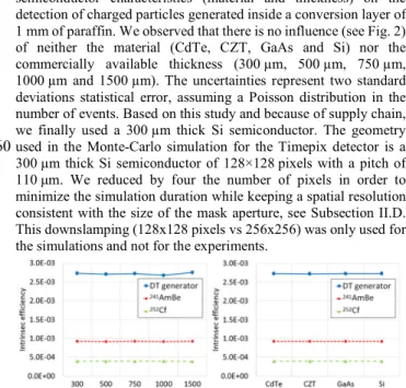
semiconductor characteristics (material and thickness) on the detection of charged particles generated inside a conversion layer of 1 mm of paraffin. We observed that there is no influence (see Fig. 2) of neither the material (CdTe, CZT, GaAs and Si) nor the commercially available thickness (300 µm, 500 µm, 750 µm, 1000 µm and 1500 µm). The uncertainties represent two standard deviations statistical error, assuming a Poisson distribution in the number of events. Based on this study and because of supply chain, we finally used a 300 µm thick Si semiconductor. The geometry used in the Monte-Carlo simulation for the Timepix detector is a
60
300 µm thick Si semiconductor of 128×128 pixels with a pitch of 110 μm. We reduced by four the number of pixels in order to minimize the simulation duration while keeping a spatial resolution consistent with the size of the mask aperture, see Subsection II.D. This downslamping (128x128 pixels vs 256x256) was only used for the simulations and not for the experiments.
Fig. 2. Fraction of proton detected per neutron simulated as a function of the substrate material for a thickness of 300 µm (left) and of the silicon thickness (right) with three neutron sources (DT generator, 241AmBe, 252Cf
70
[14]). Error bars are smaller than the plot markers.
In order to operate the Timepix detector, the bias voltage applied to the semiconductor was +50 V and the frequency clock was set at 50 MHz. The configuration at the pixel level involves the masked pixel matrix (shutting noisy pixels) and the digital-to-analog (DAC) parameters such as the THL.
A per-pixel threshold equalization is necessary to compensate the variations of the threshold that exist between each individual pixels. This procedure used the inherent electronic noise as a trigger. The system automatically adapts the offset for every pixel to be as close
80
as possible to an optimum threshold level common to all pixels. During this procedure, the noisy pixels are also identified and shut. The per-pixel threshold equalization performed was the one proposed in the Pixelman software [15].
The energy calibration (see Fig. 3) associating the ToT value to the energy deposited was carried out according to the procedure proposed in the reference [16]. We made use of 55Fe (5.9 keV), 57Co
(14.4 keV) and 241Am (17.0 keV and 59.5 keV) sources together
with fluorescent emission lines in iron (6.4 keV), copper (8.0 keV), bromine (11.9 keV), silver (22.2 keV), cadmium (23.2 keV) and
90
indium (24.2 keV). The energy calibration (see Fig. 3) obtained is comparable with previous literature results [16]. The uncertainties represent the 95 % confidence intervals from the fitting result of each peak.
Fig. 3. Dependence on particle energy of the time-over-threshold signal measured by the Timepix detector.
B. Conversion layer
Neutrons can generate charged particles through various reactions with matter. Due to the low cross-sections of fast neutrons with
100
silicon, a fast-neutron sensitive material was added. For neutron energy higher than 0.1 MeV, detection of recoil protons becomes more efficient than other classical neutron converter. At 100 keV, the cross-section is 12.7 b for the (n, p) reaction on hydrogen, 1.81 b for the (n, p+t) reaction on 3He, 0.655 b for the (n, α+t) reaction on 6Li and 0.394 b for the (n, α+Li3+) reaction on 10B. The neutron
converting material can be any hydrogen-rich material, for instance, paraffin or polyethylene. Based on Monte-Carlo simulation results (Fig. 4), the optimal thickness is around 1 mm for 252Cf and 241AmBe
and around 2 mm for the DT (14 MeV) neutron generator. The
110
uncertainties represent two standard deviations statistical error, assuming a Poisson distribution in the number of events. We deposited and unified the paraffin films on the semiconductor by heating them, piece by piece, with a heat gun. We observed that it was not easy to superimpose more than four layers without losing cohesion between the films or without bubbles appearing between the layers. Because of these fabrication restrictions, we only deposited 0.84 ± 0.24 mm of paraffin (Fig. 5). The neutron converter layer was modeled in MCNP6 by 1 mm of CH2 with a density of
0.941.
120
Fig. 4. Fraction of protons detected per neutron simulated as a function of the paraffin thickness with three neutron sources. Error bars are smaller
than the plot markers.
C. Cluster Shape Discrimination (CSP)
Single particles produce tracks in the form of clusters of pixels when interacting in the semiconductor sensor. Timepix records the position and the deposited energy in each pixel. When the sensor
130
material, thickness, and the detector settings (such as bias voltage and per-pixel signal threshold) are fixed, the morphology of the clusters is mostly determined by the particle type (see Fig. 6), the deposited energy and the charge sharing effect [17]. A homemade pattern recognition algorithm was implemented in order to establish the cluster morphology, identify and localize protons resulting from neutron interactions. First a density-based spatial clustering of applications with noise [18] algorithm with a minimum of point of one and a distance of one is used to select the clusters one by one. Morphology parameters such as the total number of pixels, width
140
and elongation of the track, number of inner pixels, occupancy rate, roundness and energy deposited density are then extracted from the clusters. The width corresponds to the minor axis of the ellipse circumscribed to the cluster and the elongation to the ratio of the major axis to the minor axis of the same ellipse. The number of inner pixels is calculated from the total number of pixels and the number of pixels composing the cluster perimeter. The occupancy rate corresponds to the ratio between the area of the square circumscribed to the cluster and the total number of pixels. Roundness is defined as the ratio of the diameter of a circle whose surface area is equal to the
150
total number of pixels to the maximum distance within the cluster.
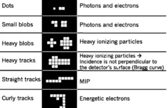
Fig. 6. Example of particle clusters classification taken from [19].
Firstly, the cluster categories and their selection criteria were defined based on the following references [19–21]. Then we adjust those to the Timepix detector for our configuration settings. We made use of photon sources (55Fe, 57Co, 241Am, 137Cs, 22Na and 60Co), - sources (14C, 36Cl and 90Sr/90Y) and neutron/photon sources
(252Cf and 241AmBe). Finally, eight cluster categories were defined
to identify the particle type, presented in Table 1. Clusters that do
160
not meet any criteria are identified as unknowns. Low energy electrons (< 100 keV) deposit their energy in a small number of pixels very close to each other: these are the small (≤ 4 pixels) and medium (≤ 12 pixels) blobs. The movement of an energetic (> 300 keV) electron being erratic, it can deposit its energy in the form of a track or a large blob (occupancy rate > 50 % and roundness > 65 %) with light energy deposited density (< 35 keV/pixel). Two types of tracks are likely to appear: curly (zero inner pixel) or large (elongation > 1.5, occupancy rate > 30 % and roundness < 50 %). In the case where the tracks is very straight (width < 2.5 pixels), it
170
corresponds to the passage of a minimum ionizing particle. Protons deposit their energy very selectively in silicon (< 3 pixels) but this energy will be distributed in the surrounding pixels due to the charge sharing effect and generate large blob with heavy energy deposited density (≥ 35 keV/pixel). When the proton has sufficient energy (> 7 MeV) and incident angle (> 45°) then the deposition will also have the characteristics of a track: these are the large heavy tracks. In our case we intend to detect recoil protons induced by neutrons with the trajectory the more perpendicular to the semiconductor surface so the selected cluster shape is the large heavy blob.
180
Table 1. Different cluster shapes associated to the type of particles and the selection criteria.
Cluster shape Type of particle Small blob Light charged particles (~10 keV) Medium blob Light charged particles (~100 keV)
Curly track
Light charged particles (>200 keV) Large light track
Large light blob
Straight track Minimum ionizing particles Large heavy track
Heavy charged particles (~MeV) Large heavy blob
Unknown Unclassified
Foremost, to qualitatively confirm the identification and localization of the protons induced by neutrons, we partially covered the Timepix chip with paraffin (see Fig. 7), exposed it to a 252Cf
source and applied the pattern recognition algorithm. The blue square in Fig. 7 and Fig. 8 represents the semiconductor surface. Experimental results show very good agreement between the covered surface (red square in Fig. 7 and Fig. 8) and the positions of the clusters classified as neutrons (blue dots in Fig. 8 (left)). For
190
visualization purpose, in Fig. 8 (left), we agglomerate four pixels into one pixel. Not all clusters classified as neutrons are localized in the paraffin surface; this presence was confirmed with MCNP6 simulation (See Fig. 8 (right)). This behavior is due to the existence of some recoil protons that may have a trajectory non-perpendicular to the semiconductor surface. In this particular case, the spot of the neutron interaction in the paraffin and of the recoil proton in the semiconductor may be completely different.
Fig. 7. Paraffin paper (red) partially covering Timepix detector (blue).
200
Fig. 8. Number of neutrons detected after exposition of the Timepix chip to a 252Cf source: experimental (left) and simulated results (right).
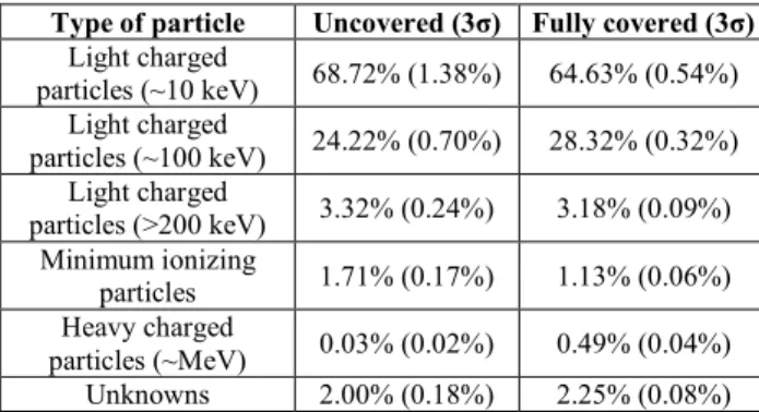
Furthermore, to quantitatively confirm the detection of protons induced by neutrons, we compare the response to the exposure of a
252Cf source of two Timepix detector: one without a conversion layer
and one fully covered by a paraffin layer. These results, given in Table 2, reveals a small but statistically significant (confidence interval > 99%) increase of 0.46% of the proportion of heavy charged particles detected (protons in our case) in the presence of the
210
conversion layer. The non-zero proportion of heavy charged particles detected even without any conversion layer suggests the existence of parasitic events. This contamination probably originates from neutron-induced reactions with the sensor’s environment and within the sensor itself of from natural radiation background. This could also come from a misidentification due the algorithm. This is still under investigation experimentally and with the help of MCNP6.
Table 2. Repartition of particles detected from a 252Cf source.
Type of particle Uncovered (3σ) Fully covered (3σ) Light charged particles (~10 keV) 68.72% (1.38%) 64.63% (0.54%) Light charged particles (~100 keV) 24.22% (0.70%) 28.32% (0.32%) Light charged particles (>200 keV) 3.32% (0.24%) 3.18% (0.09%) Minimum ionizing particles 1.71% (0.17%) 1.13% (0.06%) Heavy charged particles (~MeV) 0.03% (0.02%) 0.49% (0.04%) Unknowns 2.00% (0.18%) 2.25% (0.08%) D. Coded-aperture imaging 220
Coded-aperture patterns were developed for decades in order to improve sensitivity and angular resolution obtained with pinhole cameras. An arranging pattern of moderating and transmitting elements modulates the radiation source flux. The fast-neutron sensitive Timepix then detects the resulting coded neutron flux and thanks to the CSP algorithm, a raw neutron image is generated.
The MURA (Modified Uniformly Redundant Array) pattern [22] in square configuration was selected, based on CEA LIST knowledge following the development of the GAMPIX gamma camera [23]. This type of mask is a good trade-off between design
230
complexity, sensitivity and angular resolution. Moreover, we used the mask/anti-mask (90° rotation) method. This approach improves the image quality by reducing background events from sources outside the camera's field-of-view without using heavy shielding and by compensating the partial mask contrast achievable with fast neutrons.
The reconstruction technique used in this work is the correlation of the raw image with the decoding array. This decoding process is the usual one proposed in [22].
During our tests presented in Section III, we used a rank 3 square
240
MURA mask (see Fig. 9), made from polyethylene (CH2) and having
a planar area of 28.16 mm×28.16 mm and a thickness of 5 cm (the highest thickness we could easily process with an automated machine tool). For manufacturing purpose, we used the rank 3 with round shape holes of 5.4 mm diameter.
Fig. 9. Square MURA coded-aperture whose basic patterns measure 3×3 elements having a surface of 28.16 mm×28.16 mm.
E. Overall imager system
The communication and the control of Timepix is done using the
250
FITPix interface [24] operated through the Pixelman software. The neutron-sensitive Timepix detector, the FITPix interface and the MURA mask are integrated in the regular GAMPIX gamma camera prototype (webcam included) and form the fast-neutron imager prototype (see Fig. 10). The theoretical fully coded field-of-view of the neutron camera prototype is equal to 50 degrees.
Fig. 10. The fast-neutron imager prototype on a tripod.
The overall imager system is composed of the fast-neutron imager prototype set up on a tripod with a pan-and-tilt mechanism, a laptop
260
with the Pixelman software and an electrical power to provide the +50 V bias to the semiconductor.
III. E
XPERIMENTAL RESULTS AND DISCUSSION Firstly, we present the experimental setup and the simulation model. Then, we evaluate the neutron detection and imaging performance with a DT neutron generator.A. Experimental setup
The fast-neutron imager prototype was tested three times with the same experimental setup by using the DT (14 MeV) neutron generator of the Rapidly Relocatable Tagged Neutron Inspection
270
System (RTNIS)used in the framework of the European H2020 C-BORD project [25] (see Fig. 11).
Fig. 11. Schematic view of the RRTNIS taken from [25].
The experimental setup is shown in Fig. 12. The fast-neutron imager was positioned in front of the neutron beam aperture. The source’s geometry is a disk of 1 cm of diameter and a few millimeters of thickness. The generator is configured to emit 5×10⁷ neutrons/s.
280
Fig. 12. Fast-neutron imager set up in front of the DT neutron generator (fast-neutron beam represented by the red cone).
The geometry used in the Monte-Carlo simulation for the neutron shield around the neutron generator is exactly the same as the one presented in the reference [25]. The distance between the mask and the neutron source is 100 cm. For the 14 MeV neutron source, we used a monodirectional disk with a radius of 0.5 cm. The overall MCNP6 model of the experimental setup is shown in Fig. 13.
Fig. 13. MCNP6 model of the experimental setup with the fast-neutron
290
imager prototype and the neutron generator.
B. Neutron detection
Firstly, a measurement without the mask was performed in order to evaluate the intrinsic efficiency for neutron detection and was estimated around 0.29% (±0.01%), which is comparable with previous literature results [26] and our simulation results, see Fig. 4. It was calculated as the ratio of the number of neutron events per (cm2.s) to the neutron fluence rate through the surface of the Timepix
detector with a source at a distance of 1 m.
Then, we acquired the neutron image using the mask/anti-mask
300
method. The neutron detection stability during the measurements was checked. Fig. 14 presents the accumulated neutron count rate for one of the anti-mask measurement. The excluded data corresponds to the time before the neutron generator was activated. The neutron count rate is around 1.76 neutrons/s and is quite stable through the measurement. The uncertainties represent two standard deviations statistical error, assuming a Poisson distribution in the number of events.
Fig. 14. Cumulative distribution of neutron counts.
310
C. Neutron imaging
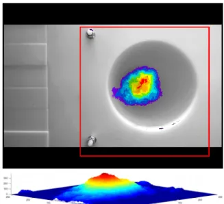
Finally, Fig. 15 shows one of the three experimental results, obtained with the neutron generator at a distance of 1 meter, centered, and for a total duration of 30 minutes (15 minutes in mask and 15 minutes in anti-mask). We applied a threshold at half the maximum to the density neutron image superimposed on the visible image in Fig. 15 (up). It can be easily observed in Fig. 15 (up) that our fast-neutron imager was fully able to localize the neutron generator. There is not any kind of interferences or misleading artifacts, even on the non-threshold neutron image in Fig. 16 (left).
320
Moreover, in the 3D profile plot (see Fig. 15 (bottom)), the hot spot is completely differentiated and the distribution around it is quite homogenous. Because the thickness of the mask is important compared to distance between the mask and the Timepix detector,
the usual definition for the Field Of View (FOV) and the angular resolution used in gamma imaging [1] is inadequate. Therefore, additional processing is still underway in order to evaluate sensitivity according to the position of the neutron source in the FOV.
330
Fig. 15. Experimental density neutron image (red frame) of a 14 MeV neutron generator with an emission of 5×10⁷ neutrons/s at a distance of 1 m
with 2×15 min acquisition times, superimposed on the visible image (up). 3D profile plot of the density neutron image (bottom).
The three identical measurements are highly similar and the consistency of experimental results Fig. 16 (left) was checked by comparison with MCNP6 simulation Fig. 16 (right). The number of particles simulated was defined so that the number of neutrons detected in the simulated raw image (3578 neutrons) was
340
comparable to the one of the experiment (3058 neutrons). In addition, Fig. 16 (left) and Fig. 16 (right) do not have the same scale because the number of pixels used in the simulation was reduced, see Subsection II.A.
Fig. 16. Experimental density neutron image reconstructed (left). Simulated density neutron image reconstructed (right).
IV. C
ONCLUSIONS AND FUTURE WORKIn this article, we present a highly compact (19×14×15 cm3,
2.2 kg) fast-neutron imager based on a MURA coded-aperture and a
350
Timepix detector enhanced with a paraffin layer. Through a series of simulations and experimental tests, we have designed a first prototype and demonstrated the feasibility of coded-aperture fast-neutron imaging based on those technologies. As it happens, we would like to point out the fact that by adding the coded-aperture in tungsten alloy of Gampix [23], our prototype can also be used as a dual particle imager.
Further investigations on the improvement of the system performances will be led. Various MURA masks (higher rank, lower thickness and different materials) are currently under design. The
360
development of other position-sensitive neutron detectors is also underway in order to increase the neutron detection efficiency. Moreover, we intend to used more advanced reconstruction process by implementing other decoding algorithms like ML-EM approaches.
Furthermore, measurement campaigns are planned with different experimental configurations and with different types of neutron sources in order to extend the characterization of the prototype.
A
CKNOWLEDGMENTThe experimental part of this work has been carried out thanks to
370
the contribution and courtesy of the C-BORD project team of the Nuclear Measurement Laboratory of CEA Cadarache Center.
R
EFERENCES[1] K. Amgarou, V. Paradiso, A. Patoz, F. Bonnet, J. Handley, P. Couturier, F. Becker, N. Menaa, C.G. Wahl, W.R. Kaye, W. Wang, F. Zhang, J.M. Jaworski, A. King, Y.A. Boucher, Z. He, A comprehensive experimental characterization of the iPIX gamma imager, J. Instrum. 11 (2016) 377–381. doi:10.1088/1748-0221/11/08/P08012.
[2] C.G. Wahl, W.R. Kaye, W. Wang, F. Zhang, J.M. Jaworski, A.
380
King, Y.A. Boucher, Z. He, Nuclear Instruments and Methods in Physics Research A The Polaris-H imaging spectrometer, Nucl. Inst. Methods Phys. Res. A. 784 (2015) 377–381.
doi:10.1016/j.nima.2014.12.110.
[3] A. Poitrasson-Rivière, M.C. Hamel, J.K. Polack, M. Flaska, S.D. Clarke, S.A. Pozzi, Dual-particle imaging system based on simultaneous detection of photon and neutron collision events, Nucl. Instruments Methods Phys. Res. Sect. A Accel. Spectrometers, Detect. Assoc. Equip. 760 (2014) 40–45. doi:10.1016/j.nima.2014.05.056.
390
[4] J.E.M. Goldsmith, M.D. Gerling, J.S. Brennan, J.E.M. Goldsmith, M.D. Gerling, J.S. Brennan, A compact neutron scatter camera for field deployment A compact neutron scatter camera for field deployment, 083307 (2016). doi:10.1063/1.4961111.
[5] J. Beaumont, M.P. Mellor, M.J. Joyce, The analysis of complex mixed-radiation fields using near real-time imaging, Radiat. Prot. Dosimetry. 161 (2014) 331–334.
[6] C.M. Whitney, L. Soundara-Pandian, E.B. Johnson, S. Vogel, B. Vinci, M. Squillante, J. Glodo, J.F. Christian, Gamma-neutron imaging system utilizing pulse shape discrimination with CLYC,
400
Nucl. Instruments Methods Phys. Res. Sect. A Accel. Spectrometers, Detect. Assoc. Equip. 784 (2015) 346–351. doi:10.1016/j.nima.2014.09.022.
[7] T.D. Jackson, Quantification of Fast-Neutron Sources with Coded Aperture Imaging, (2015).
[8] C. V. Griffith, R.S. Woolf, B.F. Phlips, 64-Element Fast-Neutron, Coded-Aperture Imager, 2017 IEEE Int. Symp. Technol. Homel. Secur. HST 2017. (2017) 1–5. doi:10.1109/THS.2017.7943453. [9] M.J. Cieślak, K.A.A. Gamage, R. Glover, Investigation into a
suitable scintillator and coded-aperture material for a mixed-field
410
radiation imaging system, J. Instrum. 12 (2017). doi:10.1088/1748-0221/12/12/P12007.
[10] J. Brennan, E. Brubaker, P. Marleau, A. Nowack, Results from field tests of the one- dimensional Time-Encoded Imaging System, (2014).
[11] J. Brennan, E. Brubaker, M. Gerling, P. Marleau, K. Mcmillan, A. Nowack, N.R. Galloudec, M. Sweany, Demonstration of two-dimensional time-encoded imaging of fast neutrons, Nucl. Inst. Methods Phys. Res. A. 802 (2015) 76–81.
doi:10.1016/j.nima.2015.08.076.
420
[12] X. Llopart, R. Ballabriga, M. Campbell, L. Tlustos, W. Wong, Timepix, a 65k programmable pixel readout chip for arrival time, energy and/or photon counting measurements, Nucl. Instruments Methods Phys. Res. Sect. A Accel. Spectrometers, Detect. Assoc. Equip. 581 (2007) 485–494. doi:10.1016/j.nima.2007.08.079. [13] J.T. Goorley, M.R. James, T.E. Booth, F.B. Brown, J.S. Bull, L.J.
Cox, J.W.J. Durkee, J.S. Elson, M.L. Fensin, R.A.I. Forster, J.S. Hendricks, H.G.I. Hughes, R.C. Johns, B.C. Kiedrowski, R.L. Martz, S.G. Mashnik, G.W. McKinney, D.B. Pelowitz, R.E. Prael, J.E. Sweezy, L.S. Waters, T. Wilcox, A.J. Zukaitis, Initial
430
MCNP6 Release Overview - MCNP6 version 1.0, 2013. [14] ISO, ISO8529-1: Reference neutron radiations - part 1:
Characteristics and methods of production, 2001.
[15] D. Turecek, T. Holy, J. Jakubek, S. Pospisil, Z. Vykydal, Pixelman: A multi-platform data acquisition and processing software package for Medipix2, Timepix and Medipix3 detectors, J. Instrum. 6 (2011). doi:10.1088/1748-0221/6/01/C01046. [16] J. Jakubek, Precise energy calibration of pixel detector working in
time-over-threshold mode, Nucl. Instruments Methods Phys. Res. Sect. A Accel. Spectrometers, Detect. Assoc. Equip. 633 (2011)
440
S262–S266. doi:10.1016/j.nima.2010.06.183.
[17] C. Granja, Z. Vykydal, Y. Kopatch, J. Jakubek, S. Pospı, S.A. Telezhnikov, Position-sensitive spectroscopy of Cf fission fragments, 574 (2007) 472–478. doi:10.1016/j.nima.2007.01.164. [18] M. Daszykowski, B. Walczak, Density-Based Clustering
Methods, Compr. Chemom. 2 (2010) 635–654. doi:10.1016/B978-044452701-1.00067-3.
[19] J. Bouchami, A. Gutiérrez, T. Holy, A. Houdayer, J. Jakubek, C. Lebel, C. Leroy, J. Macana, J.-P. Martin, S. Pospíšil, S. Prak, P. Sabella, C. Teyssier, Measurement of pattern recognition
450
efficiency of tracks generated by ionizing radiation in a Medipix2 device, in: Nucl. Instruments Methods Phys. Res. Sect. A Accel. Spectrometers, Detect. Assoc. Equip., 2011: pp. 2010–2012. doi:10.1016/j.nima.2010.06.163.
[20] T. Holy, E. Heijne, J. Jakubek, S. Pospisil, J. Uher, Z. Vykydal, Pattern recognition of tracks induced by individual quanta of ionizing radiation in Medipix2 silicon detector, 591 (2008) 287– 290. doi:10.1016/j.nima.2008.03.074.
[21] S.P. George, C.T. Severino, E. Fröjdh, F. Murtas, M. Silari, Measurement of an accelerator based mixed field with a Timepix
460
detector, (2015). doi:10.1088/1748-0221/10/03/P03005. [22] S.R. Gottesman, E.E. Fenimore, New family of binary arrays for
coded aperture imaging, Appl. Opt. 28 (1989) 4344. doi:10.1364/AO.28.004344.
[23] M. Gmar, M. Agelou, F. Carrel, V. Schoepff, GAMPIX: A new generation of gamma camera, Nucl. Instruments Methods Phys. Res. Sect. A Accel. Spectrometers, Detect. Assoc. Equip. 652 (2011) 638–640. doi:10.1016/j.nima.2010.09.003.
[24] V. Kraus, M. Holik, J. Jakubek, M. Kroupa, P. Soukup, Z. Vykydal, FITPix - Fast interface for Timepix pixel detectors, J.
470
Instrum. 6 (2011). doi:10.1088/1748-0221/6/01/C01079. [25] A. Sardet, B. Pérot, C. Carasco, G. Sannié, S. Moretto, G. Nebbia,
C. Fontana, M. Moszyński, P. Sibczyński, K. Grodzicki, L. Swiderski, A. Iovene, C. Tintori, Design of the rapidly relocatable tagged neutron inspection system of the C-BORD project, 2016 IEEE Nucl. Sci. Symp. Med. Imaging Conf. Room-Temperature Semicond. Detect. Work. NSS/MIC/RTSD 2016. 2017–Janua (2017) 7–11. doi:10.1109/NSSMIC.2016.8069693.
[26] B. Bergmann, R.O. Nelson, J.M. O’Donnell, S. Pospisil, J. Solc, H. Takai, Z. Vykydal, Time-of-flight measurement of fast
480
neutrons with Timepix detectors, in: J. Instrum., 2014. doi:10.1088/1748-0221/9/05/C05048.