HAL Id: in2p3-00021736
http://hal.in2p3.fr/in2p3-00021736
Submitted on 27 Apr 2004HAL is a multi-disciplinary open access archive for the deposit and dissemination of sci-entific research documents, whether they are pub-lished or not. The documents may come from teaching and research institutions in France or abroad, or from public or private research centers.
L’archive ouverte pluridisciplinaire HAL, est destinée au dépôt et à la diffusion de documents scientifiques de niveau recherche, publiés ou non, émanant des établissements d’enseignement et de recherche français ou étrangers, des laboratoires publics ou privés.
Neutrons for science (NFS) at SPIRAL-2 (Part I:
materiel irradiations)
D. Ridikas, X. Ledoux, F. Pellemoine, R. Anne, Y. Huguet, R. Leroy, M.G.
Saint-Laurent, A. Mosnier, F. Nizery, A.C.C. Villari
To cite this version:
D. Ridikas, X. Ledoux, F. Pellemoine, R. Anne, Y. Huguet, et al.. Neutrons for science (NFS) at SPIRAL-2 (Part I: materiel irradiations). 2003, pp.1-11. �in2p3-00021736�
Neutrons For Science (NFS) at SPIRAL-2
(Part I: material irradiations)
D. Ridikas1*, X. Ledoux2, F. Pellemoine3, R. Anne3, Y. Huguet3, R. Leroy3, S.L. Marie-Genevieve3, A. Mosnier1, F. Nizery1, A.C.C. Villari3
1) CEA/DSM/DAPNIA, CEA Saclay, 91191 Gif-sur-Yvette 2) CEA/DAM/DIF/DPTA, BP 12, 91680 Bruyeres-le-Chatel
3) GANIL, BP 55027, 14076 Caen Cedex *E-mail : ridikas@cea.fr
Material testing via irradiation in high energy and high neutron fluxes is of a great interest for very extended community working on nuclear waste transmutation (use of ADS in particular), intensive neutron sources (SNS, ESS, …), radioactive ion beam (RIB) production with neutrons (EURISOL, RIA, …), future controlled fusion experiments and reactors (ITER, DEMO, …), space applications (resistance of electronics, shielding, …), etc. In this paper we will characterise in more detail the potential of using SPIRAL-2 neutrons in this context.
A huge number of high energy neutrons (in the range between 1 and 40 MeV) produced in the carbon converter via C(d,xn) reaction will be present at SPIRAL-2 and in principle could be used for other purposes than RIB production. Mainly two different utilisation methods have been investigated: material irradiation very close to the target-converter and time-of-flight measurements with a pulsed neutron beams. Below we present only the case of material irradiation with energetic neutrons.
Basic parameters of SPIRAL-2
A huge number of high energy neutrons (in the range between 1 and 40 MeV), produced in the carbon converter via C(d,xn) reaction, will be present at the SPIRAL-2 project at GANIL (Caen, France) aiming to produce neutron-rich fission fragments [1]. The main goal of this study is to provide quantitative estimates on the possibility of using a 40 MeV (5mA) linear deuteron accelerator in a combination with a rotating carbon target, as projected at SPIRAL-2, for material irradiation purposes. It is also aimed to give a direct comparison with the ITER irradiation environment as well as the IFMIF project, introduced briefly below, in terms of available neutron fluxes, energy spectra, material damage rates and irradiation volumes.
Figure 1: Components of IFMIF: deuteron beams, lithium target and tests cells [2].
U. Fischer, Fast Neutron Physics Workshop, Dresden, 5-7 September, 2002 IFMIF Intense Neutron Source
Beam Spot (20x5cm2) High Flux Low Flux Medium Flux Liquid Li Jet Deuteron Beam
The International Fusion Materials Irradiation Facility (IFMIF) is a projected high intensity neutron source for material testing in relation with DEMO [2, 3]. It is supposed to operate in parallel with the test reactor facility ITER to support the development of materials. The concept of IFMIF is shown in Fig. 1 [2]. Two linear accelerators provide continuous-wave deuteron beams of 40 MeV, 125 mA each, with a beam spot of 20 cm × 5 cm on a flat liquid lithium jet. The irradiation cells are behind the back-plate and are subdivided into high, medium and very low flux regions.
The start of operation of IFMIF is planned beyond 2010, and is conditioned by the acceptance of the ITER construction. In addition, a number of evolution stages of the facility operation is planned with 25-50% (for a few years) and finally with 100% of the nominal beam power [2].
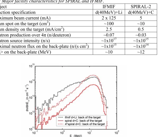
Table 1 provides basic irradiation facility specifications concerning SPIRAL-2 and IFMIF. According to very simple estimates, it seems that SPIRAL-2 would be able to provide neutron fluxes by a factor of ~10 lower than IFMIF (more detailed analysis is given in the coming section). In addition, this will be valid only for much smaller irradiation volumes (in a first approximation by a factor of ~10, i.e. ratio between corresponding deuteron beam spots on the target; more detailed estimates on this observable will be given below). Another important finding is that at forward angles the d+C reaction results in a slightly harder neutron spectrum than d+Li as shown in Fig. 2. This is due to a higher contribution of neutron production from the target fragmentation and/or compound nucleus evaporation in the case of Li.
Table 1: Major facility characteristics for SPIRAL and IFMIF.
Project IFMIF SPIRAL-2
Reaction specification d(40MeV)+Li d(40MeV)+C
Maximum beam current (mA) 2 x 125 5
Beam spot on the target (cm2) ~100 ~10
Beam density on the target (mA/cm2) 2.5 0.5
Neutron production over 4π (n/deuteron) ~0.07 ~0.03
Neutron source intensity (n/s) ~1x10¹⁷ ~1x10¹⁵
Maximal neutron flux on the back-plate (n/(s cm2) ~1x10¹⁵ ~1x10¹⁴
<En> on the back-plate (MeV) ~10 ~12
Figure 2: Comparison of neutron energy distributions on the back-plate of the production
target for IFMIF and SPIRAL-2. “4*spiral” is same as “spiral” just numbers are rescaled by a factor of 4 for direct comparison with the energy spectra of “ifmif”.
Initial considerations
All estimates in this work were done using the MCNPX code system [4] by adjusting the total neutron yield with respect to the experimental data (see Fig. 3). One can clearly see that MCNPX systematically underestimates the experimental data both over 4π and at forward angles in particular. For example, according to the existing experimental data, the d(40MeV) + Li reaction results in 0.07 n/d over 4π, while MCNPX predicts 2.5 times lower yield. Therefore, the predicted total neutron yield was renormalized according to the experimental values. On the other hand, no corrections for energy and angular distributions were made. Similar absolute neutron yield correction was adopted for the d(40MeV) + C reaction, resulting in 0.025 neutrons per incident deuteron (already corrected). Below it will be shown that our approach is justified by testing it in the case of the IFMIF neutron analysis.
Figure 3: Neutron yields (total and angular distributions) from the d+Li reactions as a
function of deuteron energy. Data points are compared with different code (MCNPX, McDeLi, McDeLicious) predictions as from Ref. [2].
Detailed comparison with ITER and IFMIF
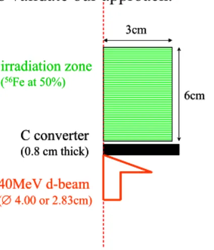
In the case of SPIRAL-2, deuteron beam of 5 mA and 40 MeV interacts with 0.8 cm thick natural carbon (rotating disk). In this study we considered that the beam spot is distributed homogeneously on xy-plane as a spherical surface of either (a) R = 2 cm, i.e. what is actually planed, or (b) R = 1.41 cm as presented in Fig. 4. The reaction d (40 MeV) + C will result in ~2.5 % neutron yield per deuteron over 4π. The irradiation volume (cylinder)
filled with 56Fe and 4He with equal occupations (50%-50%) is placed right behind the
converter target. Consequently, the sample zone had ~4 g/cm3 specific density. Partial
occupation of the irradiation volume was chosen since some artificial cooling (typically He-gas flow) might be needed during the irradiation. The irradiation zone was of cylindrical shape defined by its length of 6 cm and radius of 3 cm.
The following parameters were evaluated during the calculation procedure: neutron fluxes and their spatial distributions, energy deposition in target-converter (carbon) and in the irradiation zone (Fe-He), gas production (H and He), material damage rates (dpa), and neutron
0 5 10 15 20 25 30 35 40 45 10-1 100 101 100 101 102 MCNPX MC DeLicious Forward (Θ = 0o) MC DeLi - Daruga - Weaver - Goland - Amols - Nelson - Lone - Salmarsh - Johnson - Sugimoto Y ield, 10 10 /sr/ µ C
Deuteron Energy, MeV MCNPX MC DeLicious MCDeLi Total (Ω = 4π) - Lone - Johnson - Sugimoto - Mann Y ield , 10 10 / µ C 0 30 60 90 120 150 180 0,1 1 1 10 1 10 Ed = 15 MeV - Nelson Angle, degrees Ed = 32 MeV - Sugimoto MCDeLicious MC DeLi MCNPX Ed = 40 MeV - Salmarsh A ngu la r Neutron Y ield, 10 10 /sr/ µ C
induced radioactivity. Table 2 summarizes major irradiation characteristics for SPIRAL-2 in comparison with IFMIF, ITER and DEMO. We should emphasize that our predictions were tested in the case of the IFMIF project [2] by simulating their target and irradiation zone geometries. In general, a good agreement (better than 30 % for all observables) between existing independent calculations [2] and our work was found (compare lines 1 and 2 in Table 2). This exercise was supposed to validate our approach.
Figure 4: Target geometry used for neutron flux calculations in the case of SPIRAL-2.
Table 2: Maximal (on the target back-plate over the beam spot dimensions) neutron flux,
displacement rate, gas production and nuclear heating for IFMIF [2] and SPIRAL2 (see text for details). The fpy stands for full power year, dpa – displacement per atom, appm – atom parts per million. All values are for 56Fe.
Neutron flux, (n/(s cm2)) Damage rate, (dpa/fpy) Gas prod. (He), (appm/fpy) Gas prod. (H), (appm/fpy) Nuclear heating in 56Fe, (W/cm3) IFMIF; Ref. [2]; d-beam 5.0 x 20.0cm2 1.1x10 15 54 562 2622 23
IFMIF; this work
d-beam ∅ 5.64 cm 1.0x10 15 51 510 2036 21 SPIRAL2 (a); d-beam ∅ 4.00 cm 7.0x10¹³ 4 52 205 2 SPIRAL2 (b); d-beam ∅ 2.83 cm 1.1x10 14 7 95 378 3 ITER (max)* 4.0 x 10¹⁴ 12 140 540 12 DEMO (max)* 1.3 x 10¹⁵ 30 320 1240 35
*These are the very maximal expected values and should be considered with a great precaution.
As long as SPIRAL-2 is concerned, it could provide rather comparable
irradiation conditions as ITER. One also should note that the numbers in Table 2 for ITER
are the very maximal values, and it might be that they will not be reached during the entire experiment. It is interesting to stress at this point that, although neutron energy distribution of SPIRAL-2 (and also that of IFMIF) is quite different compared to the fluxes predicted for the first wall of ITER (and DEMO), the ratio of gas production over dpa rates is
comparable. In the case of SPIRAL-2 we obtain He/dpa = 13, H/dpa = 51, while for ITER one finds He/dpa = 11, H/dpa = 45. Another important feature of SPIRAL-2 is that
one could perform material irradiations in a variable environment in terms of sample temperatures, say, from 500°C to 1000°C or higher (see below). Therefore, in principle
40MeV d-beam (∅ 4.00 or 2.83cm) C converter (0.8 cm thick) irradiation zone (56Fe at 50%) 6cm 3cm 40MeV d-beam (∅ 4.00 or 2.83cm) C converter (0.8 cm thick) irradiation zone (56Fe at 50%) 6cm 3cm
materials could be tested at different temperatures, i.e. the radiation damage as a function of
material temperature could be examined in detail.
In comparison with IFMIF, SPIRAL-2 will be able to supply neutron fluxes by 10-20 times less important than IFMIF depending on deuteron beam density on the neutron production target (rotating graphite). In addition, useful irradiation volumes are by a factor of ~50 smaller if compared to IFMIF (see below). It is clear that a more focused deuteron
beam is preferred to obtain maximal neutron fluxes (compare lines 3 and 4 in Table 2).
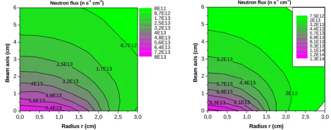
Fig. 5 shows the spatial distribution of the total neutron flux: on the left - with the deuteron beam spot of ∅ 4.00 cm, and on the right - of ∅ 2.83 cm. We remind that deuteron beam direction is along z-axis. Total neutron flux attenuation is about 30%/cm along z-axis. For high energy neutrons this decrease is somewhat lower. Some improvement (by ~20-40 %) in terms of neutron flux densities could be obtained by the use of different reflector materials around the irradiation zone [2]. More detailed analysis of this type should still be carried out. The same Fig. 5 provides us with other interesting information – a useful irradiation volume. With the following condition φn > 5x10¹³ n s-1 cm-2 & > 3dpa/fpy at SPIRAL-2 we obtain
~10 cm3 and ~14 cm3 in the case of the deuteron beam spot on the target-converter ∅ 4.00
cm and ∅ 2.83 cm correspondingly. In the case of IFMIF the corresponding numbers are as follows: with φn > 5x10¹⁴ n s-1 cm-2 & > 30dpa/fpy one obtains ~500 cm3 [2].
6,4E13 5,6E13 4,8E13 4E13 3,2E13 2,5E13 1,7E13 8,7E12 0,0 0,5 1,0 1,5 2,0 2,5 3,0 0 1 2 3 4 5 6 Neutron flux (n s -1 cm-2 ) Radius r (cm) B e a m axi s ( c m ) 8E11 8,7E12 1,7E13 2,5E13 3,2E13 4E13 4,8E13 5,6E13 6,4E13 7,2E13 8E13 9,3E13 8,1E13 6,9E13 5,7E13 4,4E13 3,2E13 2E13 0,0 0,5 1,0 1,5 2,0 2,5 3,0 0 1 2 3 4 5 6 Neutron flux (n s -1 cm-2 ) Radius r (cm) Beam axi s ( c m ) 7,5E12 2E13 3,2E13 4,4E13 5,7E13 6,9E13 8,1E13 9,3E13 1,1E14 1,2E14 1,3E14
Figure 5: Total neutron flux (n/(s cm2)) in the irradiation region, filled with 50% of 56Fe.
Deuteron beam spot on the target-converter is ∅ 4.00 cm (on the left) and ∅ 2.83 cm (on the right). Irradiation zone (cylinder) dimensions are as follows: L = 6 cm, R = 3 cm.
In Fig. 6 we present the spatial distribution of the total nuclear heating (due to neutrons and gammas taken together): on the left - with the deuteron beam spot of ∅ 4.00 cm, and on the right - of ∅ 2.83 cm. These numbers should be multiplied by 2 for temperature calculations (see below), since the 56Fe volume is 2 times smaller than the total irradiation zone, and in this case nuclear heating is present only in iron.
Fig. 7 presents the spatial distribution of the total energy deposition (deuterons, neutrons, photons, electrons, protons, tritons and alphas are taken into account) in the target-converter: on the left - with the deuteron beam spot of ∅ 4.00 cm, and on the right - of ∅ 2.83 cm. One can clearly see the Bragg’s peak at around 0.53 cm. We note separately that this primary beam energy deposition will result in a very high operational temperature of the rotating graphite-converter (see the discussion below).
0,70 0,62 0,53 0,44 0,36 0,27 0,18 0,10 0,0 0,5 1,0 1,5 2,0 2,5 3,0 0 1 2 3 4 5 6 Nuclear heating (W/cm 3 ) Radius r (cm) B eam a x is ( c m ) 0,10 0,18 0,27 0,36 0,44 0,53 0,62 0,70 0,79 0,88 0,96 0,93 0,78 0,63 0,48 0,32 0,17 0,0 0,5 1,0 1,5 2,0 2,5 3,0 0 1 2 3 4 5 6 Nuclear heating (W/cm 3) Radius r (cm) Beam axi s ( c m ) 0,02 0,17 0,32 0,48 0,63 0,78 0,93 1,08 1,23 1,39 1,54
Figure 6: Total nuclear heating (W/cm3) in the irradiation region, filled with 50 % of 56Fe.
Deuteron beam spot on the target-converter is ∅ 4.00 cm (on the left) and ∅ 2.83 cm (on the right). Irradiation zone (cylinder) dimensions are as follows: L = 6 cm, R = 3 cm.
0,0 0,5 1,0 1,5 2,0 0,0 0,1 0,2 0,3 0,4 0,5 0,6 Energy deposition (kW/cm 3 ) Radius r (cm) B e a m axi s ( c m ) 6,7 12,8 18,8 24,9 31,0 37,0 43,1 49,1 55,2 61,2 67,3 25,6 13,5 37,7 49,8 61,9 74,0 86,2 98,3 110,4 0,0 0,5 1,0 1,5 2,0 0,0 0,1 0,2 0,3 0,4 0,5 0,6 Energy deposition (kW/cm 3 ) Radius r (cm) B eam axi s ( c m ) 13,5 25,6 37,7 49,8 61,9 74,0 86,2 98,3 110,4 122,5 134,6
Figure 7: Energy deposition (kW/cm3) in the target-converter (rotating graphite). Deuteron
beam spot is ∅ 4.00 cm (on the left) and ∅ 2.83 cm (on the right), and it is distributed homogeneously along z-axis (beam direction).
Thermal conditions of the irradiation zone
It is previewed that due to the primary beam energy deposition in the rotating graphite converter its temperature will be around 1600-1700°C. In addition, some nuclear heating will be deposited in samples by interacting neutrons and photons (see Fig. 6). It complicates the thermal conditions of the irradiation zone, where the working temperature during irradiation should be rather stable and at any time must not exceed, say, 1000°C. There are a number of ways to deal with this problem. We have analysed in more detail only two of them (see Fig. 8):
a) the irradiation samples are placed in a metallic container, which is heated or cooled to reach required temperature conditions for the samples. Between the target-converter and irradiation sample there is an intermediate material zone – security window (~1cm thick graphite in yellow), which is cooled separately to a desired temperature (here we used 70°C ) in order to obtain required temperature conditions for samples;
b) the irradiation samples are placed in a metallic container, which is heated or cooled separately to reach required temperature conditions for the samples. The container in this case is situated as close as possible to the target-converter (yellow zone – security window is omitted in this case).
Figure 8: Geometrical layout of the irradiation zone used for temperature calculations. Our temperature calculations in the case of the above two options are presented in Fig. 9 (also see Table 3). In brief, in both cases the resulting sample temperature does not exceed 1000°C. However, without additional heating the temperature variations along the beam axis are rather big as indicated by donn404 and donn401 (say, from 650 down to 300°C). By external heating these variations are considerably decreased (donn402, donn403, donn405). In addition, simply by changing the power of the external heating, while keeping the same geometrical configuration, one could obtain variable thermal irradiation conditions (compare donn402 and donn403).
Figure 9: Maximal temperatures of the irradiated samples as a function of their position
along the beam axis. Foil No1 corresponds to the beginning of the irradiation zone, and foil No30 – to the end. Also see Table 3.
Irradiation sample (iron foils) Container Graphite target-converter D-beam
Optional material Container
cooling Heater Irradiation sample (iron foils) Container Graphite target-converter D-beam
Optional material Container
cooling Heater 300 400 500 600 700 800 900 0 5 10 15 20 25 30 35 N° of foil T m ax ( °C ) donn401 donn402 donn403 donn404 donn405
It is clear that further optimization studies are needed related to sample thermal conditions. However, already the preliminary estimations as discussed above are rather encouraging. One could also preview, if necessary, a dedicated cooling system (e.g., He-gas flow) of the irradiation samples as it is proposed for the IFMIF project [2]. Finally, both neutron flux as well as temperature monitoring should be planned during the irradiations. Table 3: Different geometrical configurations (donn) used for temperature calculations of the
irradiation zone. Also see Fig. 8.
Donn Radiation temperature
at entrance (°C) Addition heating power (W) Comments 401 1600 0 No optional material 402 1600 300 No optional material 403 1600 500 No optional material
404 70 0 With cooled graphite
405 70 500 With cooled graphite
Conceptual design of a dedicated plug
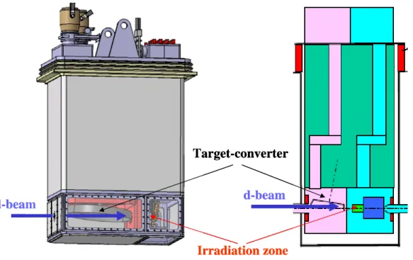
One should preview a dedicated plug(s) for irradiation purposes because irradiation samples should be placed as close to the target-converter (rotating carbon disk) as possible. In addition, the irradiated samples might need a separate cooling system (e.g. He gas or water flow) to keep their temperature at the desired level (500-1000°C). Finally, a separate-independent plug would allow accumulating irradiations up to the desired neutron fluence level during a number of separate irradiation cycles. Fig. 10 presents a detailed picture of a dedicated plug for the RIB production. In the case of irradiations, one could simply replace the UCx production target by the irradiation sample container. On the other hand, a number of important changes should be previewed due to the temperature constraints as discussed above. In addition, one should make sure that the sample container
Figure 10: A schematic view of a dedicated plug for the RIB production (source: Y. Huguet,
GANIL, 6 November 2003). Potential zone for irradiation purposes is indicated.
Target-converter Irradiation zone d-beam d-beam Target-converter Irradiation zone d-beam d-beam
a) could be easily extracted from the entire plug after the final irradiations and certain cooling time, and
b) could be finally prepared for the transportation of irradiated material for the final tests and analysis in hot and/or chemistry laboratories at CEA Saclay or CEA Cadarache, or elsewhere.
In addition to the dedicated plug, a dedicated radioactive sample handling and storage hall must be previewed. This will be needed not only for sample cooling after the final irradiation but also for a temporary storage between separate irradiation cycles. It might be that some preliminary sample examination on-site will be performed immediately after cooling or/and in between different irradiations.
Induced radioactivity of samples
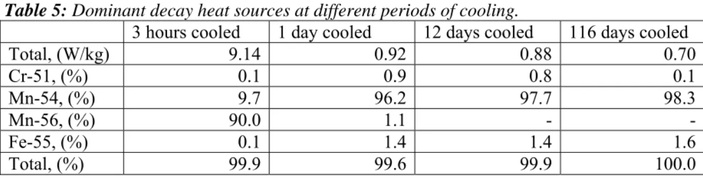
Neutron induced activation is only a primary response, which in turn leads to a number of secondary responses such as dose and decay heat. Furthermore, the activation and decay heat are time dependent results, decaying away after shutdown of the neutron source. This information is quite important due to safety, maintenance, transport and waste disposal issues. Below we present only some estimates related to the activation of natural iron in a typical SPIRAL-2 neutron environment. Our calculations were performed using CINDER’90 activation analysis code [5].
Tables 4 to 5 present the time dependence of both the specific activity and decay heat following a 1 year operation with 70% beam availability (100 days shutdown per year). The activation was calculated for a natural iron irradiated by the SPIRAL-2 maximal available flux (at the back plate). Similar estimates should be performed for all potential materials to be irradiated.
Table 4: Dominant activation products at different periods of cooling
3 hours cooled 1 day cooled 12 days cooled 116 days cooled
Total, (Bq/kg) 4.21x10¹³ 2.17 x10¹³ 2.11 x10¹³ 1.78 x10¹³ Cr-51, (%) 3.6 6.7 5.4 0.5 Mn-54, (%) 15.7 30.4 30.6 28.8 Mn-56, (%) 48.3 0.1 - -Fe-55, (%) 32.3 62.7 64.0 70.7 Total, (%) 99.9 99.9 100.0 100.0
Table 5: Dominant decay heat sources at different periods of cooling.
3 hours cooled 1 day cooled 12 days cooled 116 days cooled
Total, (W/kg) 9.14 0.92 0.88 0.70 Cr-51, (%) 0.1 0.9 0.8 0.1 Mn-54, (%) 9.7 96.2 97.7 98.3 Mn-56, (%) 90.0 1.1 - -Fe-55, (%) 0.1 1.4 1.4 1.6 Total, (%) 99.9 99.6 99.9 100.0
Planning, beam availability and costs
Beginning of the construction of SPIRAL-2 is planned in the beginning of 2006 and should be operational around 2009. It is very difficult to preview at this time how much beam
time could be possibly allocated for irradiation purposes. On the other hand, according to the above estimates one would need at least 3-4 months per year of the SPIRAL-2 primary beam at full power for irradiations, what would result in damage rates of the order of ~1-2dpa in the volume of ~10 cm3. If one requests 3-4 such irradiation campaigns at different irradiation temperatures, the irradiation experiments would last for 3-4 years depending on the beam availability. In this context, perhaps one could ask for a dedicated operation of SPIRAL-2 only for irradiation purposes during the 1st year after the facility becomes operational. In addition, to safe some time necessary for plug manipulations, change of the target-converter, delays due to some cooling time, etc., one could also think of a dedicated target station and additional beam lines for irradiation purposes.
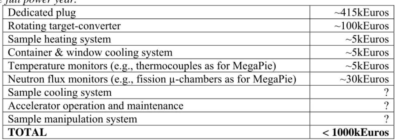
Table 6 presents preliminary cost estimates for different parts of the dedicated irradiation zone. At the moment we could not provide the costs related to the accelerator operation and maintenance. Some other numbers also should be used with some precaution. Table 5: Preliminary cost estimates of the dedicated irradiation plug with its components per
one full power year.
Dedicated plug ~415kEuros
Rotating target-converter ~100kEuros
Sample heating system ~5kEuros
Container & window cooling system ~5kEuros
Temperature monitors (e.g., thermocouples as for MegaPie) ~5kEuros
Neutron flux monitors (e.g., fission µ-chambers as for MegaPie) ~30kEuros
Sample cooling system ?
Accelerator operation and maintenance ?
Sample manipulation system ?
TOTAL < 1000kEuros
Conclusions
The SPIRAL2 facility would in principle be able to provide quite comparable neutron flux density and irradiation temperature conditions as ITER. On the other hand, in comparison with IFMIF, SPIRAL-2 would deliver neutron fluxes and damage rates by a factor of ~10-20 lower. In addition, much smaller sample volumes (by a factor of ~50) would be useful. Typical numbers for SPIRAL-2 are as follows: with neutron flux higher than ~5x10¹³
n s-1 cm-2 and material damage rates greater than ~3 dpa/fpy we obtain ~10 cm3 of a useful irradiation volume. Taking into account realistic beam availability constraints one could expect > 1 dpa per year in ~10 cm3, i.e. 4 month irradiation per year at full power. It is important to emphasise that a variable temperature environment (between 500°C and 1000°C or higher) for irradiations would be possible at SPIRAL-2.
There are no particular requirements for the deuteron beam (presently planed 40 MeV and 5 mA continuous wave deuterons) and carbon target-converter (presently planed rotating carbon target inside the plug) needed. However, we have shown that stronger deuteron
beam focalisation would increase neutron flux density and useful irradiation volume considerably (by ~40%). More detailed analysis is still needed in this context including
eventual improvement of the neutron flux in terms of different reflecting materials. Some work on the optimization of thermal irradiation conditions should be also continued. In addition, the following additional elements and infrastructure will be indispensable for irradiation purposes:
• One should preview a dedicated plug(s) for irradiations because irradiation samples should be placed as close to the target-converter (rotating carbon disk) as
possible. In addition, the irradiation zone might need a separate/different cooling system (e.g. He gas or water flow) to keep sample temperature at the desired level. Finally, a separate-independent plug would allow accumulating irradiations up to a required neutron fluence level during a number of separate irradiation cycles. One should also preview the sample extraction (from the plug) procedure.
• A dedicated radioactive sample handling and storage hall must be previewed. This will be needed not only for sample cooling after final irradiations but also for a temporary storage between separate irradiation cycles. On the other hand, similar type of target handling hall is already designed and will be used by SPIRAL-2 project. Use of it for irradiation samples should be investigated in detail.
• Transport authorization of irradiated samples should be requested. After final irradiations, the transportation of irradiated material should be feasible for the final tests and analysis in hot and/or chemistry laboratories at CEA Saclay or CEA Cadarache, or elsewhere.
Acknowledgements
The authors would like to thank A. Alamo, E.T. Cheng, U. Fischer, M. Lipa and W. Mittig for valuable discussions and comments related to this work.
References
[1] Report (white paper) “LINAG Phase I”, June 2002 , GANIL, Caen, France; available at http://www.ganil.fr/research/developments/spiral2/index.html.
[2] S.P. Simakov et al., "Neutronic Chracterization of the High Flux Test Module of the International Fusion Materials Irradiation Facility (IFMIF)”, Proc. of the Int. Conf. on Accelerator Applications/Accelerator Driven Transmutation Technology and Applications (AccApp/ADTTA'03), 1-5 June 2003, San Diego, California, USA;
S.P. Simakov et al., "International Fusion Materials Irradiation Facility (IFMIF): Neutron Source Term Simulation and Neutronics Analyses of the High Flux Test Module”, report FZKA6743 (2002), Forschugszentrum Karlsruhe GmbH, Karlsruhe, Germany.
[3] E. Daum et al., "Neutronics of the High Flux Test Region of the International Fusion Materials Irradiation Facility (IFMIF)”, report FZKA5868 (1997), Forschugszentrum Karlsruhe GmbH, Karlsruhe, Germany;
P.P.H. Wilson, “Neutronics of the IFMIF Neutron Source: Development and Analysis”, PhD thesis report ISSN-0947-8620 (1999) Forschugszentrum Karlsruhe GmbH, Karlsruhe, Germany.
[4] L.S. Waters, “MCNPXTM USER's MANUAL”, Los Alamos National Laboratory, preprint TPO-E83-G-UG-X-00001, (November 1999); also see http://mcnpx.lanl.gov/ (November 2003).
[5] W.B. Wilson, T.R. England and K.A. Van Riper,``Status of CINDER'90 Codes and Data'', Los Alamos National Laboratory, preprint LA-UR-99-361 (1999).
![Figure 1: Components of IFMIF: deuteron beams, lithium target and tests cells [2].](https://thumb-eu.123doks.com/thumbv2/123doknet/12687893.354876/2.892.293.658.852.1107/figure-components-ifmif-deuteron-beams-lithium-target-tests.webp)