HAL Id: in2p3-00397625
http://hal.in2p3.fr/in2p3-00397625
Submitted on 1 Sep 2009
HAL is a multi-disciplinary open access
archive for the deposit and dissemination of
sci-entific research documents, whether they are
pub-lished or not. The documents may come from
teaching and research institutions in France or
abroad, or from public or private research centers.
L’archive ouverte pluridisciplinaire HAL, est
destinée au dépôt et à la diffusion de documents
scientifiques de niveau recherche, publiés ou non,
émanant des établissements d’enseignement et de
recherche français ou étrangers, des laboratoires
publics ou privés.
Beam Diagnostics for SPIRAL2 RNB
P. Anger, T. André, A. Delannoy, J.M. Fontbonne, E. Gueroult, B. Jacquot,
C. Jamet, G. Ledu, N.A. Orr, A. Savalle, et al.
To cite this version:
P. Anger, T. André, A. Delannoy, J.M. Fontbonne, E. Gueroult, et al.. Beam Diagnostics for SPIRAL2
RNB. 9th European Workshop on Beam Diagnostics and Instrumentation for Particle Accelerators
(DIPAC09), May 2009, Basel, Switzerland. pp.116-118, 2009. �in2p3-00397625�
BEAM DIAGNOSTICS FOR SPIRAL2 RNB FACILITY
P. Anger, T. Andre, A. Delannoy, E. Gueroult, B. Jacquot, C. Jamet, G. Ledu, A. Savalle,
F. Varenne, J.-L. Vignet, GANIL, Caen, France, J-M. Fontbonne, N. Orr, LPC, Caen, France
Abstract
The SPIRAL2 project is based on a multi-beam driver facility in order to allow both ISOL and low-energy in-flight techniques to produce intense radioactive ion beams (RIB) in a new Facility. A superconducting linac capable of accelerating 5-mA deuterons up to 40 MeV is used to bombard both thick and thin targets. These primary beams will be used for the RIB production by several reaction mechanisms (fusion, fission, etc.) The production of high intensity RIB will be based on fission of uranium target induced by neutrons.
These exotic particles will be produced, ionized, selected in a dedicated production building and transported to the existing CIME cyclotron for post acceleration. After this, they will be used in the present experimental area of GANIL. The construction phase of SPIRAL2 was officially started in 2005.
The beam diagnostics for the production facility allow a pre-tuning with a stable beam followed by an extrapolation to the radioactive beam. Some diagnostic devices may also provide for equipment protections and for the safety systems.
An overview is presented of the diagnostics which will allow tuning and control of the RIB in this new production facility.
SPIRAL2 RNB FACILITY
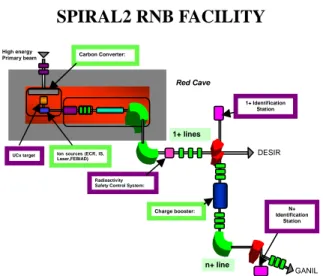
Figure 1: RNB general scheme.
The RNB facility will produce, from a high intensity primary beam, radioactive ion beam in a red radiological cave. The production of high intensity RIB will be based on fission of uranium target induced by neutrons. The mono-charged secondary beams will be selected in the 1+ beam line, used for low energy experiment or multi ionized to be post accelerated in the existing Ganil.
TUNING AND CONTROL METHODS
The tuning principle of the SPIRAL2 beams consists of pre-tuning with a stable beam followed by an extrapolation to the radioactive beam.
Figure 2: Stable beam tuning and R.I.B. tuning.
PRELIMINARY TUNING IN STABLE
BEAM
Beam Intensity Measurement
Measurement of the beam intensity in the lines is based on the use of Faraday cups (Fig. 3) and a linear current to voltage converter. Their measurement dynamics extends from 109 pps up to Imax (P<50W) with an absolute
accuracy of a few percent.
Figure 3: Faraday cup.
Beam Profile and Position Measurement
The measurement of the beam transverse profile in the lines is carried out by secondary emission multiwire profilers (Fig. 4). The principle is based on electron emission under the impact of the beam on wires. The range measurement is 109 pps – 1013 pps for energy from some keV to 25 MeV/A and the absolute positional accuracy is better than 1 mm.
It gives transverse profile dimensions and the gravity centre of the beam along a horizontal and vertical axis. This information will be distributed via electronic processing according to Ethernet or MODBUS protocol with the Spiral2 Command-Control.
Red Cave
High energy
Primary beam Carbon Converter:
UCx target Ion sources (ECR, IS, Laser,FEBIAD)
Radioactivity Safety Control System:
Charge booster: 1+ Identification Station 1+ lines n+ line GANIL DESIR N+ Identification Station Target UCx Carbon Converter Source Mass Separator Charge Breeder IBE Station Low Energy Experiment High Energy Experiment 1+ 1+ Post-acceleration by CIME Injection/Impuritie Injection/ Impurities n+ L5 Stable beam R.I.B neutrons Deuterons
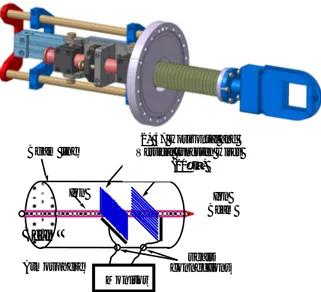
Figure 4: Secondary emission multiwire monitor, principle and picture.
For Spiral2 facilities, electronics components will be far away from the sensor to be protected from the radiation. Studies will therefore have to be conducted on a new electronic device with a length of approximately 20 m of cables (Fig. 5).
Figure 5: Spiral2 profiler acquisition principle.
RADIOACTIVE ION BEAM TUNING
Low Beam Intensity Measurement
Electrical Measurement. The intensity measurement
will have to be carried out using a Faraday cup with logarithmic current/voltage converter, like that used on the SPIRAL1 facility. Their measurement dynamics extend from some 107 to 1014 pps. This Faraday cup has electric shielding to measure weak beam intensity over a large dynamic range.
Figure 6: Faraday Cup views and logarithmic converter for low beam intensity.
Beam Radiation Measurement. In the case of “routine
intensity measurement” in beam lines, it will be possible to use devices containing implantation foil and semiconductors to measure the beam radioactivity (gamma radiation) and control the transmission in the beam line.
Figure 7: CdTe detector.
These interesting devices are under development at Ganil (resolution: 0.8 % FWHM at 662 keV).
Beam Profile Measurement
Secondary Emission Foil Profiler. Profilers with
emissive foil and micro-channel plates will also allow measurement of the transverse profile after CIME, with no lower energy limit. This is a low intensity beam profile monitor. The principle is a collection of the secondary electrons in a drift space which are amplified with an MCP stage and collected on an x-y grid for a required resolution of 1 mm. They are currently under development at GANIL (Fig. 8).
Figure 8: Secondary emission foil profiler: principle and view.
The last Ganil tests results show good performance with high energy beam (5 Mev/A) with a wide range of intensities (10 to 1011 pps). The tests will also have to show that this device can measure with a low energy beam in the 1+ and n+ lines of Spiral2 (E < 10 keV/A). Consequently, the configuration of the electric and magnetic fields will have to be extensively optimised to ensure correct guidance of the detected electrons.
Very Low Intensity and Low Energy Profiler. To
control the radioactive beam in the low energy line of Spiral2, beam localisation and beam quantification should be carried out. When there is no stable beam pollution, beam detection with electric charge measurement is possible. One solution with weak beam energy would consist in direct interaction of the beam with a
micro-Ion Monitor seals connections Beam line Beam Atmosphere 2* 47 Horizontal and Vertical tungsten wires
(20µm) Ion Beam
e
R.I.B. magnets Thick Foil FPGA Control & Treatment µP Communication between FPGA and SPIRAL2 Control System Ethernet SPIRAL2 Control SystemAutomatisms related to the sensor Control HT used in the probe
active integrator for 8 channels Front-End …12 daughters boards Acquisition principle I2C fa s t di gi ta li z a ti on Pr ofile Monit o r FPGA Control & Treatment µP Communication between FPGA and SPIRAL2 Control System Ethernet SPIRAL2 Control System
Automatisms related to the sensor Control HT used in the probe
active integrator for 8 channels Front-End …12 daughters boards Acquisition principle I2C fa s t di gi ta li z a ti on Pr ofile Monit o r
channel plate without emissive foil. This development will start in 2010.
Secondary Emission Multiwire Profiler with Gas Circulation for Post Accelerated Beam. Transverse
beam profile measurement in the lines after existing CIME cycloton will be carried out, in most cases, by profilers with gas circulation. The principle is like a gas ionisation chamber. The low limit for this profiler is due to the thickness of the input window. This sensor is under development and the results are very good: Résolution better than 1mm for 102 to 106pps with a gas pressure of 10mbar of C4H10 or C3F8 and with an input window thickness of 6um of Mylar.
Figure 9: Gas Profiler: view and principle.
DIAGNOSTIC FOR RADIOLOGICAL
DOSE CONTROL BY BEAM INTENSITY
MEASUREMENT
Beam intensity measurement by electric charge measurement is a possibility which has been studied. If the pollution by a stable beam is not too high, it would be interesting to use electric charge measurement to take a flow measurement on line, thereby limiting the activity downstream. For this, three solutions are studied.
Beam Current Transformer
It is designed for non-destructive measurement.
The coil transformer only measures magnetic field variations so beam modulation is necessary. Since the best measurement resolutions at GANIL for these sensors are of the order of nAe (≈1010 pps), an absolute threshold under all conditions lower than ≈1011 pps cannot be guaranteed.
Pick-Up
For this measurement, beam modulation is necessary too. The best measurement resolutions for these sensors at low energy (20 keV) are of the order of 10nAe (≈1011 pps), an absolute threshold under all conditions lower than ≈1012 pps cannot be guaranteed.
Figure 10: Views of the GANIL pick-up.
Faraday Cup Associated With a Fast
Electro-static Deflector
In order to provide users with a beam which is as continuous as possible, a device equipped with an electrostatic deflector in front of a low intensity Faraday cup which integrates the average intensity could be installed. This electrostatic deflector could deflect, for example, at a frequency of 1 kHz, with a useful ratio for measurement of 5 %, leaving 95 % of the continuous beam for the users (Fig. 11).
Figure 11: Faraday cup associated with a fast electrostatic deflector.
In this case, a Faraday cup resolution of 2 pAe, by guaranteeing the "deflector" function, provides an indirect resolution of 36 pAe on the beam users. This device could control and guaranty in all circumstances a user beam threshold of about 360 pAe (2*109 pps). It is sufficient.
CONCLUSION
The feedback of the Ganil and Spiral1 operation is a major factor contributing to optimum design of the Spiral2 facility and definition of the beam tuning methods. The beam diagnostic definition benefits from this feedback. Some Spiral1 diagnostics will be reused; others are in development.
However all diagnostics will have to answer:
• new and strong nuclear environment requirements (remote handling, simplicity, robustness, reliability),
• requirement for behaviour at high vacuum (low degassing rate at a pressure of 10-8 mbar in order to limit the beam losses in the n+ line).
REFERENCES
[1] M. H. Moscatello et al., Technical report of the radioactive beam section of SPIRAL2. Ganil report (2007, DECEMBER). τT 0 Vs T0 Vs max t if max t if T0 τ Q(t) Qbeam Beam line + + + ++++ ++++ -- -- - -Ifaiscea I Qwall E electrode - -1+ Beam line Faraday Cup High switched voltage at 5 % Off / 95 % On High fixed voltage Continuous beam
Beam loss measurement = Delivered Beam Intensity/19
Beam Delivered