Master of Science HES-SO in Engineering Av. de Provence 6
CH-1007 Lausanne
Master of Science HES-SO in Engineering
Orientation : Technologies industrielles (TIN)
ESPecIaL :
an Embedded Systems Programming Language
Fait par
Christopher Métrailler
Sous la direction de
Dr Pierre-André Mudry
HES-SO // Valais, Systems Engineering
Expert
Prof. Pascal Felber
Université de Neuchâtel, Institut d'informatique
Accepté par la HES SO//Master (Suisse, Lausanne) sur proposition de
Prof. Pierre-André Mudry, conseiller de travail de Master Prof. Pascal Felber, expert principal
Lausanne, 6 février 2015
Prof. Pierre-André Mudry Conseiller
Prof. Pierre Pompili
Responsable de la filière Systèmes industriels
Layout based on the EPFL EDOC LATEX 2εtemplate and BIBTEX. Report version 1.1 - April 2015.
Abstract
Nowadays embedded systems, available at very low cost, are becoming more and more present in many fields such as industry, automotive and education. This master thesis presents a prototype implementation of an embedded systems programming language.
This report focuses on a high-level language, specially developed to build embedded applications, based on the dataflow paradigm. Using ready-to-use blocks, the user describes the block diagram of his application, and its corresponding C++ code is generated automatically, for a specific target embedded system.
With the help of this prototype Domain Specific Language (DSL), implemented using the Scala programming language, embedded applications can be built with ease. Low-level C/C++ codes are no more necessary. Real-world applications based on the developed Embedded Systems Programming Language are presented at the end of this document.
Contents
ESPecIaL - an Embedded Systems Programming Language i
Abstract v
1 Introduction 1
2 State of the art 3
2.1 Block-based programming . . . 3
2.1.1 The Scratch programming language . . . 3
2.1.2 Turtle graphics . . . 5
2.1.3 Modkit . . . 6
2.1.4 Related work . . . 7
2.2 Dataflow and flow-based programming . . . 8
2.2.1 NoFlo . . . 9
2.2.2 LabVIEW . . . 10
3 An embedded programming language 11 3.1 Specification . . . 11
3.2 Architecture . . . 13
3.3 The Scala programming language . . . 14
3.3.1 Internal DSL . . . 14 3.3.2 External DSL . . . 16 3.4 Dataflow model . . . 16 3.5 Execution model . . . 17 3.5.1 Synchronous dataflow . . . 18 3.6 Components library . . . 19 4 Backend 21 4.1 Target selection . . . 21 4.2 Development kit . . . 22
4.2.1 Development environment and toolchain . . . 23
4.3 Hardware Abstraction Layer . . . 24
4.4 Design and implementation . . . 25
4.4.1 General Purpose Input/Output . . . 26
4.4.2 Analog-to-Digital Converter . . . 27
Contents
4.4.4 Universal asynchronous transmitter . . . 27
4.4.5 Delays and timers . . . 27
4.4.6 Available inputs and outputs . . . 28
4.5 Extension board . . . 28 4.6 Testing . . . 29 5 Frontend 31 5.1 Introduction . . . 31 5.1.1 Development environment . . . 31 5.1.2 Pipeline . . . 32
5.2 Code generation pipeline . . . 33
5.2.1 Component manager . . . 34 5.2.2 Components ports . . . 37 5.2.3 Dot generator . . . 39 5.2.4 Code optimizer . . . 40 5.2.5 Code checker . . . 42 5.2.6 Resolver . . . 43 5.2.7 Code generator . . . 45 5.2.8 Code formatter . . . 48
5.3 Compilation & simulation pipeline . . . 49
5.3.1 Real target . . . 49
5.3.2 ARM emulator . . . 49
5.3.3 Automated tests . . . 51
5.4 DSL improvements . . . 53
5.4.1 Components and pins definitions . . . 53
5.4.2 Anonymous components . . . 53 5.4.3 Pins functions . . . 55 5.4.4 Variadic constructors . . . 55 5.4.5 Boolean operators . . . 56 5.4.6 Custom components . . . 57 6 Real-world applications 61 6.1 Majority function . . . 61 6.1.1 Simulation . . . 63
6.1.2 Digital timing diagram . . . 65
6.2 Regulation application . . . 66
7 Conclusion 71 7.1 Summary . . . 71
7.2 Limitations . . . 72
7.3 Future work . . . 72
Bibliography and appendices 74
A Extension board 78
Contents
B Development environment 79
B.1 Backend (C/C++) . . . 79
B.2 Frontend (Scala) . . . 80
B.3 ARM emulator (QEMU) . . . 81
B.4 Hardware . . . 81
C Hardware Abstraction Layer 82 D Sample code generation 84 E Generated VCD file 88 F Majority circuit 89 F.1 Simulation . . . 91 G Regulation application 95 List of tables 100 List of figures 102 List of programs 104
Chapter 1
Introduction
Embedded systems are becoming more and more present. They are very popular, widely used and cheap. A multitude of these systems are available on the market. As an example, Arduino boards have a great success. These development boards are available at very low cost and allow to build applications using a specific language, similar to C or C++. Other ARM based computers, like the Raspberry Pi, are more powerful systems. They are used a lot in the educational field, especially to introduce programming concepts at school (for instance using the Python programming language). Several Visual Programming Languages (VPL) have been developped for educational purposes. They help to build applications using a visual editor and avoiding to use a specific programming language. Some of these visual languages will be presented in the chapter 2. The majority of them are used to build games or animations on computer. The other part have been developed specially for embedded systems.
Developing applications for embedded systems is hard because low-level programming languages are necessary. Some proprietary tools helps to convert an UML model (for instance a class diagram) to a generated C/C++ or Java code. Rational Rhapsody1is one of this tool. Unfortunately, the generated code produced by this tool cannot be executed directly : some methods must be implemented manually using low-level C/C++ code. Depending on the target, other adaptations are necessary. Based on theses observations, the goal of this project is to build a new prototype programming language for embedded systems. Using a specific syntax based on the dataflow paradigm, this high-level language allows to describe the behavior and the block diagram of an application (not its concrete implementation). Using ready-to-use components available in the framework, the user can connect blocks together to build the application. Each block can be seen as a black-box, with inputs and outputs, used to compute predefined functions. These blocks are used to build the logic of the application and also to control specific peripherals of the embedded system. Then, the developed framework generates automatically the C++ code corresponding to the application. The code can be used out of the box to program the target embedded system.
Chapter 1. Introduction
As a proof of concept, the embedded systems programming language is developed using an internal Domain Specific Language (DSL) in Scala. With the help of this high-level language, embedded applications can be built with ease, avoiding the use of low level programming languages like C or C++. This prototype language helps non programmer users to build portable applications for embedded systems.
Outline
Before presenting the developed framework specification, some existing visual programming lan-guages and tools will be presented in chapter 2. Instead of writing textual programs, two visual approaches are introduced : block-based and dataflow programming.
Then, the project architecture overview and the specification of the prototype language are detailed in chapter 3. Some specific features of the Scala programming languages, especially Domain Specific Language (DSL) are introduced.
Chapters 4 and 5 focus on the programming language implementation. The features of the language are presented using simple example applications. The whole transformation process from the application definition to the code generation, simulation and tests is described in details.
Then, the language is shown "in action" in the chapter 6. Two real-world applications developed using the embedded system language are presented. To check the behavior of these applications, two testing approaches have been used.
Finally, the chapter 7 concludes the report, by presenting achieved results and by giving some recommendations and further directions for the project.
Chapter 2
State of the art
Visual programming languages (VPL) are now common, for instance in the educational field to learn basic programming concepts to children. Several programs also includes a visual programming editor to develop simulations, games, automated processes or to create sounds and movies. Instead of writing textual programs using codes, these programs are built graphically in an easy-to-use editor. The model of the application is described visually. It is an abstraction of the concrete implementation, and no code is required. A complete snapshot of available visual programming languages can be found online [Hos14]. Today, VPL are available to describe all kind of programs, in many areas. Programs can be represented visually in different manners. It can be using blocks, flowcharts or dataflows for instance. A selection of some existing programming languages will be presented in this chapter. Some of them have been developed for education purpose, others especially for embedded systems. Two visual paradigms will be presented in the next two sections.
2.1 Block-based programming
The first type of visual programming language presented here consists of writing applications like puzzle. An application is composed by blocks, which can be combined together to create a program. No code is required, the application is built graphically using a drag&drop interface. Some block-based programming language are presented in the next sections.
2.1.1 The Scratch programming language
Scratch [MIT14] is a free visual programming language developed by the MIT Media Lab. Scratch 1.0 was released in 2007, but it is based on a quite old language called Squeak (created in 1996), which is a dialect of the Smalltalk language, created in 1972.
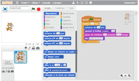
Scratch is a programming language and online community, designed specially for young people, to create interactive stories, games, and animations with ease, using a visual editor. Ready-to-use blocks are connected to each other, like a puzzle, to create a program (a script). 145 blocks1can be used to control active objects, called "sprites" (inspired by EToys programming language). An offline desktop editor is available, and also a web-based editor, presented in figure 2.1. They are both implemented using Flash.
Chapter 2. State of the art
The program is described visually using blocks on the right of figure 2.1. A color corresponds to block category, like motion, events, control, or sensing. All these blocks, combined together, are used to control and animate one or more sprites, drawn on the top left on figure 2.1. Each block has a special slot, to prevent syntax errors. Basic programming concepts, like loops, conditional tests and variables can be used. Images and sounds can be also added and the user can control a program using mouse and keyboard events. A nice feature of Scratch is that programs can be updated dynamically, when running.
Figure 2.1 – Web based development environment of Scratch 2.0
Limitations
Scratch is multimedia and educational oriented. Programs are described using colorful blocks only. It is not possible to add code (in text format) to write more complex or specific blocks. Scratch supports only basic types: from Scratch 1.4, floating point numbers and some limited functions on strings are supported. The last Scratch version, released on May 2013, now supports custom blocks. They can be used ot create reusable functions with input parameters if needed, but no code can be inserted. An extended implementation of Scratch, called Snap! [MH14] is another programming language which allows to build custom blocks.
The scope of the Scratch programming language is limited. The version 2.0 of the language adds an extension protocol2available to connect Scratch desktop applications with the physical world. Javascript or HTTP extensions add specific blocks, available to control external hardware. Some projects are listed bellow :
• The first project is a simple extension board used to connect desktop Scratch programs to the physical world. The PicoBoard contains a slider, a button, analogs inputs and a few other sensors. Connected through USB, custom blocks are available to control the extension board. • The LEGO WeDo Javascript extension add blocks to control the LEGO WeDo Robotic Kit,
composed by motors and different sensors (light distance, tilt).
2 http://wiki.scratch.mit.edu/wiki/Scratch_Extension_Protocol_(2.0)
2.1. Block-based programming
• Finally, some other experimental projects allow Scratch programs (running on desktop) to communicate with Arduino boards. Arduino For Scratch (A4S)3use the Firmata protocol to communicate with the Arduino board. A second project, S4A (Scratch For Arduino)4interact with Arduino by sending actuators states and receiving sensor states each 75 ms. Both of these projects are experimental and use the Scratch extension protocol to interact with the editor. All values are transmitted from/to Arduino using a serial connection over USB, and then sent over HTTP to the Scratch IDE.
Scratch has been developed for children, for educational and multimedia purpose, but not for embedded systems. It is widely used by students, schools or teachers to easily create simple games or simulations and learn how to program using a graphical editor. There is also a big community and a lot of Scratch program example are shared. Programs are build like puzzle using blocks, which are great to prevent syntax error.
Some experimental projects presented above can be used to communicate with embedded systems, like Arduino boards. Scratch programs are always running on the desktop and inputs/outputs values are transmitted from the embedded device to the PC over USB.
Finally, Stencyl5is a project which extends the Scratch’s simple block-snapping interface with new functionality and blocks, to create games for mobile, web and desktop, always without writing code.
2.1.2 Turtle graphics
Turtle graphics is inspired by the Logo programming language [Tho83] in the late 1960s. The TurtleArt [Sug14] has been developed to draw images, using a relative cursor in a two-dimensional plan. The cursor used to draw the image, represents the turtle. Here is an example of a turtle graphics environment :
Figure 2.2 – Drawing a filled shape using TurtleArt (source [Sug14])
The turtle, used to draw images, has 3 main attributes: a position, an orientation and a pen (with a color, a width, etc.). A program is composed by a sequence of instructions used to control or move the turtle. In figure 2.2, the program is defined using blocks, in a similar way to the Scratch language. Using these blocks, it is very easy to draw simple images.
3 https://github.com/damellis/A4S
4 http://s4a.cat/
Chapter 2. State of the art
Extended TurtleArt versions are also available. They offer advanced functions to build complex images (using geometrical operations for instance) and more than one turtle can be used. Some advanced applications and results are presented on this website [Sug14].
Many TurtleArt implementations are available. They usually offer a graphical environment to create programs using blocks, like Scratch (see previous section 2.1.1), but TurtleArt programming languages are also available. Programs can be built using specific sequential commands. As an example, a Java implementation is available here6. Another interesting open source application, named Kojo7, can be used to program turtle graphics. Kojo is a complete learning environment developed in Scala, which includes many different features, not only turtle graphics.
2.1.3 Modkit
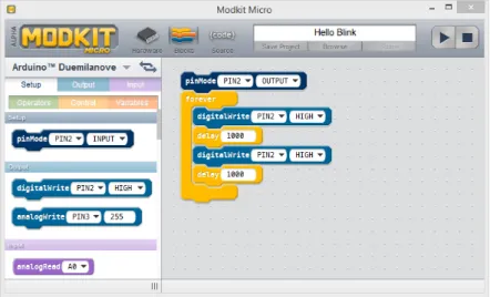
Modkit [Mod15] is a more recent project, born in 2010 from a Kickstarter project. It is again a visual programming environment, specially developed to program embedded systems. It is heavily inspired by Scratch. Based on the same blocks concept, this drag&drop programming environment makes embedded systems programming easy and accessible to everyone. The Modkit desktop application is presented in figure 2.3.
Figure 2.3 – Modkit micro desktop application
Modkit is compatible with many hardware. All Arduino8and Arduino like boards are compatible targets. Specific blocks are available to configure and control input and output pins of the board. The program is composed by these blocks, like in Scratch or TurtleArt.
With Modkit, in addition to the block interface of figure 2.3, two other views are available. The first view can be used to configure the pins of the selected target as input or output. Depending on the target, specific pins can be configured as analog or digital. The second view displays the generated code, but this code cannot be modified. It is generated automatically from the visual interface (the opposite way is not available).
6 Turtle Graphics with Java -http://www.java-online.ch/lego/legoEnglish/turtleGrafik.php
7 The Kojo Learning Environment -http://www.kogics.net/kojo
8 Arduino open-source electronics platform -http://www.arduino.cc/
2.1. Block-based programming
The generated code 2.1 corresponds to the LED blinking program of figure 2.3 : 1 void setup() { 2 pinMode(PIN2, OUTPUT); 3 } 4 5 void loop() { 6 digitalWrite(PIN2, HIGH); 7 delay(1000); 8 digitalWrite(PIN2, LOW); 9 delay(1000); 10 }
Listing 2.1 – The generated code for an Arduino board
This code is automatically generated from the blocks and cannot be edited. Each block are translated to a C code to create a sequential program (imperative paradigm). The generated code can be used to program the Arduino board, without modification. The board can be linked to the Modkit environment using an USB cable. This part has not been tested, but once the environment is configured and the board detected, the play button should program the target and run the application automatically. The program can only be ran, not debugged, and unfortunately no simulator are available.
Modkit makes embedded programming easy. It is compatible with many targets and a single applica-tion is used to develop, compile and run the program with ease. It is great to learn programming in the educational field and to build simple applications.
Unfortunately, only a few control and operator blocks are available. Furthermore, it is only possible to control analog and digital I/O. Embedded systems have more and more power and advanced peripherals. For now, all target features cannot be used. Modkit is still in an alpha version, more functionalities will be probably added soon.
2.1.4 Related work
Several visual block-based programming languages have been presented in the previous sections. Open source libraries, like Google Blocky [Goo14], can be used to build such visual editors with ease. These type of block-based languages are very common today. Other related projects like Bitbloq or Ardublock, based on the same programming paradigm as Scratch, have been developed specifically to generate programs for embedded systems (like Arduino).
One advantages of these languages is that the sequential generated code looks like the visual program description, and using blocks makes syntax errors completely impossible [Goo14] (no unbalanced parentheses, no missing semicolons, etc.). Visual block-based languages are excellent educative tools and make the programming accessible to kids (no code is required). Unfortunately, complex programs are verbose and not easy to develop, and blocks functionalities can be limited (see the Modkit project in section 2.1.3 for instance).
Chapter 2. State of the art
2.2 Dataflow and flow-based programming
Dataflow and flow-based programming are two other approaches to describe programs visually. These visual programing paradigms will be covered and explained in this section. Some projects that use each of theses approaches will be presented later.
First, terms of dataflow and flow-based can be confusing because they both define visual program-ming paradigms and execution models. In both cases, applications are defined using "black-boxes" components, connected together to exchange data and information. Applications are represented using graphs. The nodes of the graph are the components and connections are the arcs between them. A simple Flow-Based Programming (FBP) diagram is presented in figure 2.4 :
Figure 2.4 – A Flow-Based Programming diagram (source [Mor13])
Before describing how such applications are defined, it is important to distinguish the differences between these two paradigms. According to this article [Mai13], the two models are explained bellow :
1. Flow-based programming
Flow-Based Programming (FBP) is a particular form of dataflow programming, invented by J. Paul Morrison in the early 1970s [Mor13]. This paradigm usually mean asynchronous dataflow programming [Mai13]. In this model, nodes are constantly waiting for messages. Data between nodes are event-based and asynchronous channels are used. Each node of the graph are connected with ports, implemented for instance with queues to continually receive messages from other nodes (like streams). Applications are not defined by a single sequential process, but by a complex network of asynchronous processes [Mai13].
2. Dataflow programming
Dataflow is the synchronous approach. It corresponds more to conventional synchronous programming. This time, the graph is executed in a sequential order. A node is executed once when the data of all its inputs are ready. The node output is computed and the result "flows" to the input of the next node. The same process is executed again and again, until all nodes have been executed [Mai13]. In this model. the scheduler is much more simple because nodes are executed once, in a sequential order.
The "Advances in dataflow programming languages" [JHM04] article reviews many developments that have taken place within dataflow programming languages in the past decade. Other dataflow execution models are also presented in details. This other article [WP94] presents the history and evolution of dataflow languages. Not all of them will be covered in this document, but some projects and software based on the synchronous and asynchronous dataflow programming model will be presented in th next two sections.
2.2. Dataflow and flow-based programming
2.2.1 NoFlo
Different FBP implementations are available. The NoFlo9project is one of them. It was created in 2013 from a KickStarter campaign and is presented here.
NoFlo is a JavaScript (more precisely CoffeeScript) implementation of Flow-Based Programming. It is based on NodeJs and runs in a browser. NoFlo components can be used to build software, defined as graphs. Components are connected together with ports and messages are used to communicate between the components. For instance, components can react to HTTP requests, to writing data to a database. NoFlo applications are built using a web-based editor. NoFlo UI is the name of their IDE for flow-based programming.
NoFlo became popular and similar project have been created or are based on it. One example is the MicroFlo10experimental project. It is a flow-based programming runtime for microcontrollers (like Arduino). It is inspired by and designed for integration with NoFlo. Simple applications can be developed visually using the NoFlo UI, but according to the documentation project, it is too early to use it for general tasks.
An other interesting point of NoFlo is that applications can also be developed using a specific Flow-Based Programming language11. This is a Domain-Specific Language (DSL) for easy graph definition. The following example presents how to use this DSL to blink a LED. Using MicroFlo, the code 2.2 can be executed on Arduino for instance.
1 # LED blinking on Arduino
2 # https://github.com/microflo/microflo/blob/master/examples/blink.fbp
3 timer(Timer) OUT -> IN toggle(ToggleBoolean) 4 toggle() OUT -> IN led(DigitalWrite)
5 '300' -> INTERVAL timer() 6 '13' -> PIN led()
Listing 2.2 – Led blinking example in Microflo
The graph application can be created using a visual tool or using the DSL (by writing code). Then, the program 2.2 is converted to a command stream and embedded into the firmware image, which can be loaded on the microcontroller. Finally, the network graph is executed on the device (standalone). At this stage of the project, the execution model and the scheduler implementation are quite simple and limited (see10, network execution). Components are naively scheduled. Messages are stored in queues and are delivered to the corresponding components in the main loop of the program. It is expected that scheduling will grow more complicated over time, to support for instance asynchronous input events/interrupts, fair division of the processing time, etc.
Systems based on FBP are growing. The flow-based programming introduction article of J. Paul Morrison [Mor13] presents a lot more projects based on FBP, which implement some or all FBP concepts.
One more interesting example is the Node-RED project. It is a visual tool for wiring Internet of Things application, developed by IBM. Node-RED also provides a browser-based flow editor. It works on the same principle as NoFlo and can be extended with custom blocks (Javascript code).
9 Flow-Based Programming for JavaScript -http://noflojs.org/
10 Flow-based programming runtime for microcontrollers -https://github.com/microflo/microflo
Chapter 2. State of the art
Finally, Node-RED can be executed on the BeagleBone of the Raspberry Pi, using a NodeJs server. Custom components are available to use GPIO within the Node-RED Javascript environment. For this, native libraries must be installed on the hardware.
2.2.2 LabVIEW
The synchronous dataflow approach is presented using the LabVIEW software as an example. LabVIEW is a scientific software system for laboratory automation and simulation [KMR91]. This professional software, developed by National Instruments and available since 1986, is widely used in the industry. It is a very complete software used to describe visually many types of applications with advanced structures, hierarchical diagrams, etc. It can be also used to develop graphical interfaces. LabVIEW programs (block diagrams) are described using a dataflow representation. An example is shown in figure 2.5 :
Figure 2.5 – Dataflow programming example in LabVIEW (source [Ins15])
LabVIEW is a well-known DataFlow Visual Programming Language (DFVPL) [JHM04] developed for professional users but not programmers. Ready-to-use components are available in the software and applications can be built using a drag & drop interface. This helps non-programmer users to build complex applications to control an equipment or an automated process in LabVIEW for instance. According to the official LabVIEW documentation [Ins15], LabVIEW follows a dataflow model. A block diagram node is executed when it receives all required inputs. When a node executes, it produces output data and passes the data to the next node in the dataflow path.
The visual language embedded in LabVIEW is called "G". It is based on the dataflow model, but it is extended with graphical control flow structures. This allows to extend the pure dataflow model, because it is too restrictive for the typical applications of LabVIEW [VM99]. Control structures are available in the "G" language. For instance, aforloop structure allows to run a subgraph for a predefined number of times. The summary of the "G" language is available in this article from National Instrument [KMR91].
Finally, many additional toolkits are available to extend the software, for instance to build real time or embedded (DSP) applications.
Chapter 3
An embedded programming language
3.1 Specification
Several existing visual programming languages (VPL) have been presented in the previous chapter. They use different approaches to represent a program visually, instead of describing it with codes, using blocks (flowcharts) or dataflow diagrams. In this chapter, the overview and the specification of the prototype embedded system programming language will be presented.
Modkit, Bitbloq or Ardublock are some projects, presented in the last chapter, developed specifically for embedded systems. All these environments are block-based. The program is described visually, and a sequential C code is generated. The generated code is very similar to its visualization because blocks (like loops, if/case statements and math operators) are very close to the language.
In contrast to block-based VPL, the language developed during this project allows to describe the model and the behavior of a program, and not its concrete implementation. It is an high level language for embedded systems, used to express in a natural way the block diagram / the behavior of the application. According to these articles [HCRP91, Qua04, JHM04], dataflow programming languages are particularly well suited for this purpose.
The embedded system can be seen as a black box (shown in figure 3.1), connected to several external components like buttons, LEDs, actuators, sensors, etc.
A
Y
X
User application Dataflow based
Chapter 3. An embedded programming language
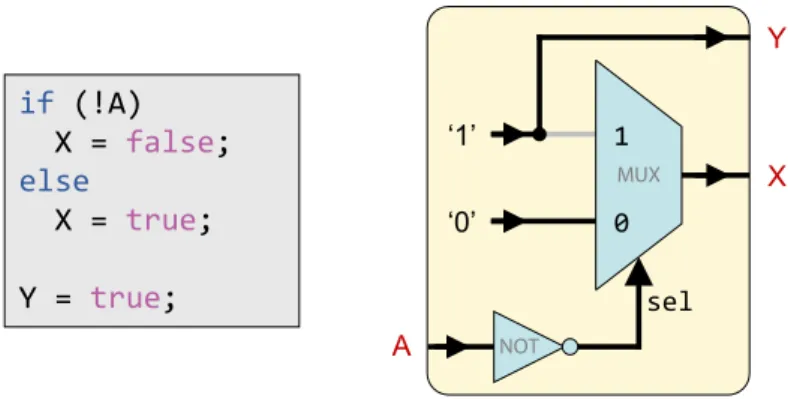
Figure 3.2 shows a typical (simple) application which can be expressed using the developed dataflow language (it will be presented later). The pseudo-code on the left defines the application specification. Its dataflow representation is available on the right : instead of using a textual representation (a code), the application specification is described visually.
if (!A) X = false; else X = true; Y = true; MUX sel A ‘0’ ‘1’ 1 0 X Y
Figure 3.2 – Pseudo-code translated to a dataflow representation (adapted from [VBCG04]) In this simple example, The outputYis always ON.Xis ON only when the inputAis low.
The dataflow representation (see section 2.2 on page 8) is composed of "black-box" components. Each box is a single function : the application above is composed by a multiplexer bloc, constants values and an inverter gate. Inputs and outputs of these blocs are connected together to form a DataFlow Graph (DFG). The DFG of the application 3.2 is the following :
in NOT gateNot [1] out
in1 in2 sel Mux2 [3] Mux2 out uint8 Constant [4] constant generator
(true) out bool
bool bool bool Constant [7] constant generator (false) out bool A Y X
Figure 3.3 – DataFlow Graph (DFG) of the application 3.2
The graph contains the four blocks that compose the application. Inputs are on the left, outputs on the right. Components output ports are connected to input ports in a directed graph. Dependencies between the components (nodes), and the type of the data that "flows" between them are also represented in such a graph. Primitive types of data are exchanged between the components, like bool, integer or floating point values. Each component has a generic number of input and output ports. By convention, they are namedoutorout1,out2, etc. if many are available (the same for inputs). Ports with a specific function are named with a custom name, like the selection (sel) input port of the multiplexer.
The developed language is a high-level language used to describe any DAG (the block diagram of the application) in a natural and concise way, using a specific "dataflow" syntax. The code 3.1 is the textual representation of the application graph 3.3.
3.2. Architecture
1 val mux = Mux2() // Components decalartion 2 val not = Not()
3
4 mux.out --> X.in // Connecting ports 5 A.out --> not.in
6 not.out --> mux.sel
7 Constant(true).out --> mux.in1 8 Constant(false).out --> mux.in2 9 Constant(true).out --> Y.in
Listing 3.1 – Dataflow Domain Specific Language of the application 3.2
This program is a Scala Domain Specific Language (DSL), similar to the flow-based programming language available in NoFlo (see section 2.2.1 on page 9). Severals components are available in the developed framework. Using a specific Scala syntax, components ports are connected together using the "-->" operator (an output port to an input port).
Unlike imperative programming, a dataflow program is not represented by a linear instruction sequence, but by its DFG [Fin95, Chapter 6]. This graph give the execution order of the code. The instruction order of the code 3.1 is not important. It must only be a valid Scala code. Components must be declared before being used, but the ports connections order is not important. Output can be connected before inputs for instance. The execution model will be presented later in this chapter.
3.2 Architecture
The code architecture overview of the project is presented in figure 3.4.
The traditional way used to program embedded systems is shown on the left. The user application is developed in C or C++, and libraries are used to control the microcontroller peripherals, I/O, etc. Depending on the target, proprietary tools and toolchain are necessary to program/debug the target. Another approach used in this project is presented on the right of figure 3.4. This other approach is now composed by two parts. The main difference is that an automated tool converts the model of the application, described in a dataflow graph, to the native C/C++ application for the embedded system. The frontend part, written in Scala, transform the dataflow model (its graph) to a C/C++ code. This generated code is generic and based on a Hardware Abstraction Layer (HAL) to control the microcontroller peripherals. This allow to support multiple targets, without modifying the high-level application. The backend must be developed once for each target, and then no more low-level C/C++ is required. As a proof of concept, two targets will be supported for this project : a generic ARM development kit and a simulator based on QEMU which emulates the real target. They will be presented in the next chapters.
The application model is specified using a custom dataflow DSL, like the program 3.1. The Scala programming language and more specifically Domain Specific Language (DSL) are presented in the next section.
Chapter 3. An embedded programming language ESPecIaL Timers PWM GPIO Interrupts UART SPI / I2C USB CAN A/D HAL + libraries User application C/C++
Shared drivers / API
Target Cortex M3 HAL QEMU drivers Simulator Generated application (C/C++) Code generator Components library ... User application High-level language (DSL) Backend Frontend Auto.
Figure 3.4 – Project architecture overview
3.3 The Scala programming language
The SCALAprogramming language1, has been developed since 2001 in the programming methods laboratory at EPFL (Switzerland).
According to [Typ14a], Scala is a general purpose programming language designed to express common patterns in a concise, elegant, and type-safe way. The Scala syntax is lightweight and its primitives expressive [OSV08]. It integrates features of object-oriented and functional languages. Scala programs run on the Java Virtual Machine (JVM) and are compiled directly to regular Java bytecode. Therefore, Scala is interoperable with Java: a Java code can be accessed from and to Scala programs.
In addition to these advantages, Scala also supports Domain Specific Language (DSL). DSL are languages developed to express a custom problem (for a specific need). One well-known example is Matlab. It integrates a DSL to do numerical computing, using a specific syntax. Another example is the NoFlo DSL, presented in section 2.2.1 on page 9.
In this project, the user application will be described using a custom high-level language, based on Scala. The next two sections are focused on two Scala DSL types. They will be presented and also compared to other languages, like DSL build in Java or with other libraries.
3.3.1 Internal DSL
The first type of DSL are called internal DSL. Internal DSL are great to extend the Scala language itself. Features can be added to language to meet specific needs. Internal DSL are built using the Scala compiler, this implies that its syntax must be valid in Scala (the host language).
DSL are a powerful Scala feature [Bag09]. To extend the language, natural looking DSL can be written using features directly available in the Scala language itself. Possibilities are somewhat limited, but the Scala syntax [Ode14, p. 159] is flexible enough to built great internal DSL.
1 The Scala Programming Language -http://www.scala-lang.org/
3.3. The Scala programming language
Some key advantages, described in this book [Gho10] and these articles [Oa04] [Ber11] are summa-rized bellow :
• First, semicolons, dots and parenthesis, are optional in Scala (but still necessary in some cases). Compared to Java where these characters are mandatory, they are now considered as "noise" in Scala. For instance, Scala has a special syntax for invoking methods of arity-1 (one argument) without using dot and parenthesis. The Scala syntax [Ode14, p. 159] is flexible (more than Java for instance), so it possible to create less verbose, more user-friendly and more natural languages without much effort.
• The Scala syntax also allow to use any ASCII character for method names and Unicode symbols for operators. This can greatly improve the readability of the code.
• Implicit conversions are widely used to automatically convert built-in type to custom objects to extend the language. Combined with operator overloading, they allow to write concise codes, once again.
• Finally, Higher-order Functions (HOF), currying and curly braces (to make code blocks) can be used to makes user-friendly DSL.
DSL are widely used in Scala to extend the language. To illustrate some of the features enumerated above, the code 3.2 presents a DSL available within the Scala library. TheDurationclass and the Futuretrait (both available in thescala.concurrentpackage2) extend the language to write and use asynchronous computations with ease, in a more natural way.
1 import scala.concurrent._
2 import scala.concurrent.duration._
3 import scala.concurrent.ExecutionContext.Implicits._ 4
5 object DemoFuture extends App { 6
7 val f: Future[Long] = future {
8 val t = (Math.random() * 3000).toLong // Simulate an HTTP request 9 Thread.sleep(t)
10 t // Return the computation time
11 } 12
13 f onSuccess {
14 case r => println(s"Future done in $r ms.") 15 }
16
17 // Waits 2 seconds for the Future result, or throws a TimeoutException
18 Await.ready(f, 2 seconds)
19 // Same as : "Await.ready(f, Duration(2, SECONDS))" (without DSL)
20 }
Listing 3.2 – A Scala internal DSL example using aFuture
Chapter 3. An embedded programming language
In the example 3.2, an HTTP request is simulated with random time. On line 21, we wait on the Futureresult (a success or a failure) for 2 seconds at most. If this maximum time is reached, a TimeoutExceptionis thrown and the program terminates. If not, future result is printed.
On lines7,13and18, some of Scala features enumerated above make the code more readable and concise (with a minimum of "noise"). For instance, using implicit conversions, timeouts, which are often used with futures, can be simply written as "2 seconds", like a human readable text.
Internal DSL built using Java for instance are more verbose because characters must be added to be conform to the Java syntax.FactoryorBuilderpatterns [Gho10] can be used to create fluent interfaces [FE05]. This help to build more natural Java internal DSL, but the Java syntax is more strict and more rigid. As a result, internal Java DSL are less attractive because they will always be more verbose (with noise) and less flexible than one built in Scala.
3.3.2 External DSL
Another type of DSL are called external DSL. In this case, the language is parsed using an external tool or a built-in library, and the DSL syntax is totally independent of the host language. Unlike internal DSL, all syntaxes can be supported.
Parser combinators3are a way to build parsers using the Scala programming language. As of Scala 2.11, parser combinators are available in an external library, but they are part of the language specification. The grammar of the parser can be described using a particular syntax, directly in Scala using an internal DSL.
Other Scala parser libraries are available. One alternative to the Scala parser combinators is Parboiled4, which can also be used to build external Java DSL. Finally, ANTLR (ANother Tool for Language Recognition) [Par13] is another parser generator that can be used to built external DSL in Java. In this case, the grammar of the parser is described in an external file using an EBNF syntax, and not directly within Java.
External DSL can be built either in Scala or Java with one of these tools. Using Scala parser combina-tors, the grammar of the parser is written using an internal DSL, in a very consice form, directly in the Scala language. No external files are needed, so the program is less verbose.
3.4 Dataflow model
In a previous introductory project, I had the opportunity to work with internal and external DSL, using Java and Scala parser combinator and the aforementioned libraries.
For this prototype language, the dataflow program will be described using an internal Scala DSL. According to the section 3.3.1, Scala is great to build internal DSL. Its syntax is flexible enough to write a dataflow program (like the code 3.1 on page 13) in a natural and concise way. Furthermore, the Scala compiler helps a lot to check the validity of the user-application at the compilation time. Finally, the user can extend the DSL with ease, which is not possible with an external DSL.
3 Scala Standard Parser Combinator Library -https://github.com/scala/scala-parser-combinators
4 Parsing library for PEGs grammars -http://parboiled.org/
3.5. Execution model
Projects like LabVIEW, NoFlo or Node-RED (presented in section 2.2) have a graphical interface to build applications. In this project, as a proof of concept, dataflow applications will be described textually and not graphically.
In a next version, a web-based editor, similar to Node-RED or NoFlo, could be implemented. Once the programming language is implemented, the development of the graphical interface is straightforward, because the program view can be translated one-to-one to the corresponding code.
3.5 Execution model
The block diagram of the application, stored in a dataflow-graph is transformed to a embedded C++ application. The goal of the project is not to develop a compiler (which could generates an assembly code or an LLVM bytecode for instance), but to generate a ready-to-use C/C++ application.
The C/C++ code is generated specially for embedded systems. A quite simple execution model has been chosen, so the application can be ran on most all embedded systems (also those with limited resources). The skeleton of the generated C++ application is presented below :
1 int main() {
2 init(); // Components, target and peripherals initialization 3
4 while(1) {
5 // 1) I: Read Input
6 // 2) P: Process logic (execute the graph)
7 // 3) O: Update outputs
8 }
9 }
Listing 3.3 – Skeleton of the generated C++ application
The target system is used as "bare machine". This means that the application runs in a single and monolithic "thread", without any operating system or complex execution frameworks. When the application starts, themainfunction is called, followed by initializations functions and finally the infinite main loop, as presented in the code 3.3. Using the developed HAL library, the application can be compiled for the target using a standard toolchain.
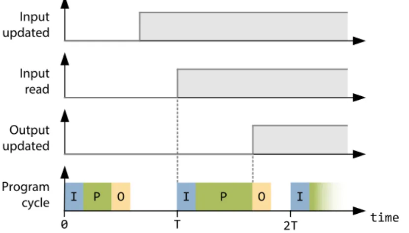
The dataflow graph is transformed to a sequential application and executed in the main loop, accord-ing to the Input-Process-Output (IPO) model. It consists in periodically readaccord-ing the program inputs, then computing the dataflow graph, and finally writing the program output values.
The generated sequential application corresponds to the Grafcet execution in a Programmable Logic Controller (PLC) [GF13]. In this execution model, all inputs of the program are read at the same time, and then all outputs are updated, also at the same time.
The dataflow graph is executed in a periodic or non periodic cycle. A program cycle corresponds to one iteration of the while loop. The C/C++ code of each node/component of the dataflow graph is executed in the main loop, in a particular order, to take into account the dependencies between the nodes.
Chapter 3. An embedded programming language P I O P O I Input updated Input read Output updated Program cycle T 0 2T I time
Figure 3.5 – Periodic I/O scanning, IPO model (adapted from [GF13, p. 10])
3.5.1 Synchronous dataflow
To be able to transform any dataflow graph into an efficient sequential program, the dataflow must be restricted to a synchronous dataflow [HCRP91]. A synchronous dataflow is a particular type of dataflow which allows a static scheduling (known at compilation time) [HCRP91]. From a dataflow graph perspective, this means that the graph must be restricted to a Direct Acyclic Graph (DAG). The topological sort of the DAG gives the order in which nodes must be executed.
DAG are a specific type of graphs. Nodes are connected together with directed edges (arcs), such that no directed cycles can be created. The following figure shows a DAG :
Cmp6 Cmp1 Cmp3 Cmp2 Cmp4 Cmp5
Figure 3.6 – An example of a Directed Acyclic Graph (DAG)
The graph of the figure 3.6 is a valid DAG because no directed cycles are formed by the arcs. The dataflow representation allows isolated nodes (likeCmp3). We can also identify source (input) nodes, likeCmp1andCmp2, because they have 0 incoming edges (indegree zero). As opposite, the nodeCmp6 is a sink (outdegree zero) connected with 2 incoming edges.
The order of the nodes execution in thewhileloop is given by computing the topological order of the DAG. The graph sorting is done by the frontend part, before generating the application. This allows to run an efficient sequential program on the embedded system, avoiding the overhead of a run-time scheduling [TMPL95], which can be a performance issue for embedded systems.
The topological ordering of a DAG is not unique and must corresponds to the IPO model. It will be explained in details in the chapter 5, in the frontend implementation description.
3.6. Components library
3.6 Components library
We have developed several components that can be used by the user to build the dataflow applications. The figure 3.7 shows the main components (dataflow blocks), classified by types.
Target specific Generic I/O Fixed I/O Core Math Logic Board Or
Not Digital input
And Analog input Pulse counter PWM output Digital output Mux Constant Tick toggle PID regulator Add Mul Sub Div Components Trigger
Figure 3.7 – Available components classed by type
A first category of component, called "target specific" allows to control the hardware and the periph-erals of the target, to read or write digital/analog values for instance. To do this, specific libraries and low-level code is necessary, for each supported target. The model of these components is described in the Scala frontend, and their concrete C/C++ implementation in the backend. The implementation of these target specific components is based on a generic interface, an Hardware Abstraction Layer, presented in the next chapter.
The other components allows to describe the logic of the program. The majority of the developed components can be used with a generic number of input, like multiplexer, all logic gates and math blocks. These components are implemented in the frontend, using a generic C/C++ implementation. Currently, not so many components are available, but thanks to the Scala internal DSL, new compo-nents can be added with ease, depending on the user needs. In the chapter 6, real-world applications, based on these components will be presented.
Chapter 4
Backend
The first technical part of the project consists in developing a low level C/C++ code for the chosen embedded system (the target). First of all, a development board has been selected for the project. The hardware and its toolchain are presented below.
Then, an Hardware Abstraction Layer (HAL) has been developed. Its specifications and implemen-tation are detailed in the second part of the chapter. The role of this software layer is to provide a generic way to access to the microntroller inputs, outputs and peripherals. All (developed or gen-erated) applications running on the target will use this abstraction layer to control the hardware. Target specific components presented in figure 3.7 on page 19, like digital I/O, PWM output, etc. are implemented in C/C++ for the chosen target.
In the last part of the chapter, a sample C++ application based on the developed HAL presents how the hardware and its peripherals can be accessed and controlled with ease. The HAL provides a high abstraction level and helps to add new compatible targets in the future.
4.1 Target selection
The embedded system programming language developed during this project can be compatible with several hardware, as long as a backend is available (has been developed) for the target.
For this project prototype and as a proof of concept, one hardware as been selected among many possible choices. The goal of the project is not to develop a specific hardware, so a development board available in the market has been chosen.
Two constraints have been considered for the selection. First, it is important to have a low-level access to the hardware and its peripherals, and the possibility to develop on the hardware without operating system (bare machine). This is why Raspberry Pi and alternatives boards have not been selected. Secondly, the target should be sufficiently powerful to not be limited during the developments (PIC, AVR or MSP processors can be too limited).
Chapter 4. Backend
4.2 Development kit
The selected target for the project is based on a 32-bit ARM Cortex-M3 processor. These processors are very common, they offer rich connectivity, good performance and are available at low-cost. Many manufacturers propose this type of processor, like Atmel, NXP Semiconductors, Texas Instruments and STMicroelectronics.
Several development kits based on these processors are available at low-cost. As a result, I chose a development kit available on the market I had experience with. It is based on theSTM32F103 Performance Line MCU [STM14a]. This microcontroller combines a powerful ARM Cortex-M3 CPU with an extensive range of peripheral functions and enhanced I/O capabilities :
• STM32F103RBT6ARM 32-bit Cortex-M3 CPU Core (128KB flash, 20KB SRAM) • 72 MHz maximum frequency
• LQFP64package (10x10mm), 51 fast I/O ports
• Main peripherals : USB, CAN, I2C/SPI, ADC, UART, timers
The chosen development kit, presented in figure 4.1, is manufactured by Olimex [Oli14] and is available for less than 50$. Its features are summarized bellow. Not all theses peripherals will be used during the project.
• One user buttons, a joystick and a status LED
• LCD NOKIA 3310 black/white, 3-axis accelerometer, SD-MMC connector, 2.4 Ghz wireless transceiver, audio in/out, USB mini connector
• Two extension connectors
• Standard JTAG connector for programming and debugging
Figure 4.1 – Olimex ARM Cortex-M3STM32-103STKstarter-kit board (90x65mm)
One user button, a joystick and a LED are available directly on the board (an Analog to Digital Converter is necessary to get the joystick direction). The kit is flexible and has been designed for many applications purposes. External peripherals can be added using the two 14-pin connectors to 22
4.2. Development kit
extend the board capabilities. For the needs of the project, and extension board has been developed. It will be presented later in this chapter, in section 4.5 on page 28.
All technical specifications and the development kit schematics are available on the manufacturer website [Oli14]. I/O types and pins numbers are detailed in appendix A on page 78.
4.2.1 Development environment and toolchain
The backend has been developed and tested on theSTM32-103STKstarter kit. The figure 4.2 is an overview of the tools and the hardware used to developed on the ARM Cortex M3 target.
.mk User application source files Builder (make) GNU ARM Toolchain (gcc, g++, ld) Library stm32f10x_lib Programmer & Debugger (GDB, OpenOCD) ARM executable file Eclipse CDT GNU ARM .elf .c .cpp Generated Makefile JTAG adapter Hardware Software Target STM32‐103STK Generated files Source files
Figure 4.2 – Software tools and hardware overview (adapted from [HES14])
The development environment is free of charge. It is based on the Eclipse CDT (C/C++ support) IDE and the GNU ARM toolchain1(arm-none-eabi), which compiles all C/C++ source files into an ARM executable file. The project makefile is generated automatically by Eclipse.
When the elf file is generated, GDB and OpenOCD are used to program and debug the code on the target. A standard ARM JTAG 20-pin connector is available on the target. An home-made JTAG is used, but any generic JTAG should be fine (an OpenOCD configuration file is required). Detailed tools versions and hardware references are available in appendix B on page 79.
This environment has been tested on Linux, but it is cross-platform. Eclipse settings and tools setup are described on the Wiki of the school [HES14]. All developments, later described in this chapter, are included in the developedstm32f10x_libC++ library (see figure 4.2). It is shared and used by different projects and demo applications.
The chosen development board [Oli14] is shipped with demo applications. The kit is widely used and many example codes are available. Projects like this one2and thelibheivs_stm32library [HES14] have been used as a starting point. Some files have been used and adapted for the project needs. Finally, the source code documentation has been generated with Doxygen.
1 GNU Tools for ARM Embedded Processors -https://launchpad.net/gcc-arm-embedded
Chapter 4. Backend
4.3 Hardware Abstraction Layer
Many embedded systems are available, with different specifications and peripherals. To hide differ-ences between hardware, an Hardware Abstraction Layer (HAL) has been developed.
The HAL presented in the center of the figure 4.3, is a software layer used by all applications to uniform the control and the access of the hardware (the MCU and its peripherals). This layer allows to run the same user application on different targets, without modifications, because all I/O and peripherals are accessed through this abstraction layer. For each target, a specific HAL must be implemented.
User application C/C++
HAL / drivers
GPIO
Interrupts UARTA/D TimersPWM Microcontroller (MCU) Input/Output abstraction
Peripherals abstraction
Standard Peripheral Library / OS
Figure 4.3 – Hardware Abstraction Layer
To support several targets, the HAL unifies the control and the access to the five following inputs, outputs and peripherals :
1. General Purpose Input/Output and external interrupts (IRQs)
General Purpose Input/Output (GPIO) are used to read or write digital values from generic pins of the processor. All GPIO are identified by a unique port and a pin number. They can be configured either as input or output to read or write boolean values. Input values can be polled or inputs can be configured as external interrupts to be notified automatically (using a function callback) when its value change.
2. Analog input
Some specific inputs can be configured as analog inputs. In addition to the GPIO, they are iden-tified by a unique channel number, connected to one or several Analog-to-Digital Converters.
3. Analog output
The reverse operation consist of converting a digital number to an output voltage, using a Digital-to-Analog Converter (DAC). DAC are not often available on low-cost embedded systems. An alternative consist of using Pulse-Width Modulation (PWM) signal to simulate an analog output. The frequency and duty cycle of the output signal can be configured. If necessary, an external analog circuit can be used to filter this signal.
4.4. Design and implementation
4. Logging and debugging
A serial interface is available to log events and print messages from the microcontroller to an external console (UARTover RS232). This logging interface is useful for debugging purpose. Events can be sent to trace the code execution.
5. Timer (delay and time measurement)
Finally, delays (busy waiting) are available to wait some time, expressed in milli or microseconds. An hardware timer can also be used to count the elapsed time without blocking the code execution.
4.4 Design and implementation
This section describes the HAL implementation developed for theSTM32-103STKdevelopment kit, presented in section 4.2 on page 22.
The toolchain (see section 4.2.1) supports C++, and the target is powerful enough (no performance issue), so it would be too bad to not use object oriented features of the C++ language. The HAL implementation will be more structured, and OO features makes the code more flexible and highly portable to support other targets, by usingBuilderandFactorypatterns, interfaces, etc.
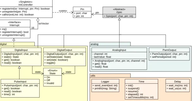
The C++ HAL implementation for theSTM32-103STKboard is summarized in the UML class diagram of figure 4.4 (it has been simplified, the full documentation is available in Doxygen) :
digital analog utils 16 Logger + send_event(evt: int) + println(msg: String) «Singleton» IntController
+ registerInt(isr: Interrupt, pin: Pin): boolean + unregisterInt(pin: Pin)
+ callIsr(extLine: int): boolean
«Interface» Interrupt + irq() + registerInterrupt(): bool + unregisterInterrupt() Pin + port: char + pin: int «Abstract» Gpio
+ Gpio(port: char, pin: int) + initialize(): boolean
PulseInput + PulseInput(port: char, pin: int) + get(): boolean + read(): boolean + time(): int «uses» isrVector Time + init() + suspend() + resume() + elapsed(): int + setTimeoutMs(ms: int) state state «Enum» State + On + Off + Invalid pin AnalogInput - channel: int - lastValue: float
+ AnalogInput(port: char, pin: int, channel: int) + get(): float
+ read(): float DigitalInput
+ DigitalInput(port: char, pin: int) + state(): State
+ get(): boolean + read(): boolean
DigitalOutput + DigitalOutput(port: char, pin: int) + setState(state: State) + set(state: boolean) + toggle()
PwmOutput + PwmOutput(port: char, pin: int) + setPeriod(period: int)
Delay + wait_ms(ms: int) + wait_us(us: int)
Figure 4.4 – UML class diagram of the HAL implementation
The HAL contains the low level implementation of all target specific components available in the framework (see figure 3.7 on page 19), like digital inputs, PWM outputs, A/D converter, etc. Their implementation is detailed separately later in this section.
Chapter 4. Backend
Inputs and outputs are grouped in two main packages :digitalandanalog. Each I/O is identified by a port and pin number, which correspond to a physical pin of the MCU. The abstractGpioclass is the base class used by all I/O. Theinitializemethod is implemented by each subclass to configure the pin automatically, behind the scene, as required. All pins can be used as general purpose. Some specific pins can also be configured as alternate function, to be used as analog inputs, timer outputs, external interrupts, etc.
The HAL uses theStdPeriphlibrary to access to the MCU peripherals. The STM32F10x Standard Peripherals Library [STM14c] is a vendor specific hardware abstraction layer for Cortex-M3 processors. The library is provided by STMicroelectronics and contains low level C functions to configure and access all peripherals of theSTM32F10xCortex-M3 MCU.
All information about the processor implementation and its peripherals are available in the reference manual [STM14b]. This document contains more than 1000 pages. The main hardware specificities and implementation details used to develop theSTM32HAL are summarized in the next sections.
4.4.1 General Purpose Input/Output
Each physical pins of the microcontroller are grouped by ports and identified by a unique number. Up to 51 GPIO are available. Each of these pins can be configured for a general purpose, as input or output.
TheDigitalOutputclass configure any pin, specified by a port letter (fromAtoG) and a pin number (from 1 to 15) as a digital output. The clock of the corresponding port is enabled and the pin mode configured as an output in push-pull mode. Once initialized, is it set automatically to off. Operator overloading are available toseta boolean value to the output (positive logic).
Any pin can also be configured as a digital input using theDigitalInputclass. Inputs pins are configured as floating inputs (without any internal pull-up or pull-down resistor). To read the current input value, thereadfunction must be used. This allows to read an input pin value by polling.
External interrupts
It is also possible to configure the pin as an external interrupt. TheIntControllerclass manages all external interrupt lines (up to 16). When an input is configured as an external interrupt, an interrupt is triggered on the rising and falling edges and the input value is automatically saved. Thegetfunction will return the input pin value, automatically saved in the ISR routine. This is faster than polling the input pin.
To use an input as external interrupt, some hardware limitations [STM14b, p. 208] must be taken into account. First, only 16 external interrupts lines are available and secondly, they are internally connected in the specific manner, presented in figure 4.5.
GPIO are multiplexed and grouped by pin number to use all the 16 available lines [STM14b]. This limitation must be taken into account when external interrupts pins are chosen. For instance, it is not possible to differentiate thePA0and thePB0input because there are connected to the sameEXTI0 interrupt line (pin numbers must be different). In the current implementation, digital inputs are initialized as external interrupts by default. This is more efficient than polling the input value. The registerIntmethod of the interrupt controller is called automatically when the input is initialized.
4.4. Design and implementation EXTI0 PA0 PB0 PC0 PD0 PE0
EXTI0[3:0] bits in AFIO_EXTICR1 register
PF0 PG0 EXTI1 PA1 PB1 PC1 PD1 PE1
EXTI1[3:0] bits in AFIO_EXTICR1 register
PF1 PG1 EXTI15 PA15 PB15 PC15 PD15 PE15
EXTI15[3:0] bits in AFIO_EXTICR4 register
PF15 PG15
Figure 4.5 – External interrupt/event GPIO mapping (adapted from [STM14b])
4.4.2 Analog-to-Digital Converter
Two 12-bit A/D converters are available to measure 16 external analog sources (not all GPIO can be used). TheADC1converter is used to measure analog inputs using a single conversion mode. An AnalogInputis a specific pin identified by a unique port, pin and channel number (from 0 to 15). Thereadfunction start and A/D conversion and returns the result when it is completed.
4.4.3 Pulse-width modulation
PWM outputs are generated using 16-bit hardware timers. The frequency and the duty cycle of these outputs can be configured. Only specific pins can be used as PWM outputs. They must be configured as alternate function to be internally connected to timer outputs, using thePwmOutputclass. The pin must be configured as a push-pull output. Then, depending on the pin number, the corre-sponding timer is automatically configured in PWM mode. For now, only the 4 channels of the timer 4 can be used as PWM outputs.
The PWM duty cycle of each output can be configured using thesetPeriodfunction. A 100% duty cycle corresponds to a period of 0xFFF (12-bit resolution). This implies a maximum PWM frequency of about 9 kHz. No Ditigal-to-Analog Converter (DAC) are available in the chosen MCU, but PWM outputs can "simulate" it.
4.4.4 Universal asynchronous transmitter
TheLoggerclass can be used to transmit (Tx) messages from the MCU to an external serial console. This is useful for debugging and to trace the code execution. The receiver module (Rx) is currently not available and not used. TheUSART2serial output is configured as follow :
• 115200 baud, 8-bit data and 1 stop bit, no parity bit / no hardware flow control
A custom tracer is used to connect the serial output of the development kit to a PC USB port.
4.4.5 Delays and timers
The developed HAL provides utilities functions to deal with the time :
1. Delays functions are available to wait from 1µs to a few seconds, using busy-waiting.wait_us andwait_msare both blocking functions.
Chapter 4. Backend
2. To count the elapsed time (without blocking the code execution), the timer 2 is used as an hardwareSysTicktimer. Each 1 ms, a shared counter variable is incremented to count the elapsed time in milliseconds (using thetime_getfunction).
Time and delays implementation has been adapted from thelibheivs_stm32library [HES14] to work with theSTM32F103processor running at 72 MHz.
4.4.6 Available inputs and outputs
The table 4.1 summarizes all inputs, outputs and peripherals of theSTM32F103-STKdevelopment kit that can be accessed using the developed HAL. They are classed by types.
I/O type Available Limitation
General-purpose input 51 -General-purpose output 51
-External input interrupt 16 EXTIlines only. Pin numbers must be different Analog input (12-bit ADC) 16 All analog channels
PWM output 4 Timer4output channels only
UART (Tx, debug) 1 USART2Tx only
Table 4.1 – Accessible I/O using the Hardware Abstraction Layer
4.5 Extension board
50 x 80 mm
To the main kit
STM32F103‐STK LED4 LED3 LED2 LED1 Button1 Button2 Button3 Potentiometer EXT
Figure 4.6 – The extension board An extension board has been designed to add inputs
and outputs to theSTM32-103STKkit (presented in section 4.2). With only one button and one LED avail-able on the main kit, possibilities were too limited to test real-word and complex applications.
The prototype extension board, presented on the right in figure 4.6, has been designed on a stripboard, a rapid prototyping technique.
A 4-pin connector (EXT) can be used to connect ex-ternal peripherals with ease. LEDs or buttons can be disconnected using jumpers. To develop this board, constraints described in the previous section have been taken into account (see table 4.1). For instance, buttons are connected to external interrupts lines on different pin numbers.
The extension board schematic with pin numbers and I/O types is available in appendix A on page 78. In a next version, the extension board can be miniaturized using SMD components to be connected directly on the bottom of the main kit.
4.6. Testing
The following I/O are available on the developed extension board to extend the main kit :
I/O type Description
Digital input 3 push buttons, connected on interrupts lines (EXTI) Analog input 1 potentiometer connected to an analog input Digital output 4 LEDs (2 yellow, 2 red)
PWM output The 2 red LEDs can also be controlled as PWM outputs Table 4.2 – Available inputs and outputs on the developed extension board
4.6 Testing
The developed HAL, packed into thestm32f10x_liblibrary, allows to access with ease and a high abstraction level to the main peripherals of the MCU. The sample C++ application 4.1 demonstrates how the HAL can be used to control inputs and outputs pins of the extension board and components presented in the previous sections. For space reasons, some lines have been removed. The full application code is available in appendix C on page 82.
The demo application 4.1 uses several peripherals of the extension board. When the application starts, a debug message is printed and theled1is switched on. The button 2 controls theled2and the potentiometer value set the intensity of theled3using a PWM output. Finally, using the time utilities functions, theled4blinks every 0.5 seconds. Thanks to the C++ implementation of the HAL, methods likesetorgetcan also be replaced by equals operators to make applications less verbose and more user friendly (see line 20 or 24 of the code 4.1 instance).
The toolchain presented in section 4.2.1 on page 23 is used to compile the application. A sample Eclipse project is available in thestm32Git repository to compile and program the application on the real target. The extension board must be connected to the main kit. The figure 4.7 shows an oscilloscope screen capture of two PWM signals, generated by two PWM outputs (≈ 9kHz, duty cycle of 25% and 50%).
The developed HAL uniforms the access and the control to all inputs and outputs, so they are all created and initialized using the same approach (see lines 1 to 4 of code 4.1). Methods with an high abstraction level are available to use all target specific components presented in the figure 3.7 on page 19. If the constraints of the table 4.1 on page 28 are satisfied, any component can be automatically initialized on the desired pin. This was a quite big implementation challenge, because clocks, peripherals and all registers must be initialized correctly in a generic manner, according to the port and the pin number of the components.
All C++ applications running on theSTM32P103-STKboard will access to the peripherals and I/O through the HAL. This makes user applications highly portable and new targets, like ARM Cortex development kits, can be added without much effort. Thanks to the HAL, the component model implementation in the frontend part is much simplified. It is presented in the next chapter.
Chapter 4. Backend
1 AnalogInput adc1('B', 0, 8); // Potentiometer 2 PwmOutput pwm3('B', 8); // led3
3 DigitalInput btn2('C', 1);
4 DigitalOutput led4('B', 9), led2('C', 4), led1('C', 3); 5 6 void initIO() { 7 btn2.initialize(); 8 // ... 9 } 10 11 int main() { 12 time_init();
13 initIO(); // Init all I/O and set to '0' 14
15 println("HAL sample application"); // Print to USART2 16 led1 = true; // Led1 is on
17
18 timeout_t time = time_get(); 19 while (1) {
20 led2 = btn2.get(); // Led2 is controlled by btn2 (use EXT interrupt line) 21 pwm3 = adc1.read(); // Start an A/D conversion to read the potentiometer value 22
23 if(time_diff_ms(time_get(), time) > 500) { 24 time = time_get();
25 led4.toggle(); // Led4 toggles every 1/2 seconds
26 }
27 }
28 return 0; 29 }
Listing 4.1 – Part of the HAL demonstration application
Figure 4.7 – Oscilloscope capture of two generated PWM signals 30
![Figure 2.5 – Dataflow programming example in LabVIEW (source [Ins15])](https://thumb-eu.123doks.com/thumbv2/123doknet/14987247.672403/20.892.100.764.442.669/figure-dataflow-programming-example-in-labview-source-ins.webp)


![Figure 4.2 – Software tools and hardware overview (adapted from [HES14])](https://thumb-eu.123doks.com/thumbv2/123doknet/14987247.672403/33.892.130.795.344.590/figure-software-tools-hardware-overview-adapted-hes.webp)
![Figure 4.5 – External interrupt/event GPIO mapping (adapted from [STM14b]) 4.4.2 Analog-to-Digital Converter](https://thumb-eu.123doks.com/thumbv2/123doknet/14987247.672403/37.892.130.782.125.322/figure-external-interrupt-mapping-adapted-analog-digital-converter.webp)