JOHN DANA NAUMAN
B.S., South Dakota School of Mines and Technology Rapid City, South Dakota
1972
Submitted in partial fulfillment of the requirements for the degree of
DOCTOR OF SCIENCE
at the
Massachusetts Institute of Technology September 1976
Signature of Author S... -. ... . ... . . ...
DeDartment of Materials Scipnce and Engineering August 9, 1976 Certified by ...
"e,''f"''''''''---
. .. .. ...I/ I` Thesis Supervisor
Accepted by
... "
"
...
..
. .. .
... ...
Chairman, partmental CoTmittee on Graduate StudentsArchi
FP 3O
39
76
ABSTRACT
ANALYSIS OF HEAT TRANSFER IN SILICATE SLAGS by
JOHN DANA NAUMAN
Submitted to the Department of Materials Science and Engineering on August 9, 1976 in partial fulfillment of the requirements for the degree of Doctor of Science.
The heat transfer in ferrous silicate slags was studied by measuring the rise in the temperature of a cold metal sphere which was immersed in the liquid slag. Several liquid silicates at iron saturation were studied. These oilicates included synthetic iron refining and copper smelting slags. The experimental variables were the initial temperature of the sphere, the size of the sphere, the composition and density of the sphere, the temperature of the liquid slag, and the convection of the liquid slag around the sphere. The types of convection were natural convection, forced convection by spinning the sphere, and forced convection by bubbling gas into the slag.
To provide a general understanding of the heat transfer from the liquid slag to the cold metal sphere, a mathematical model of the flow of heat was developed and tested. The model was used to calculate the temperature distribution in the metal sphere and the solid slag shell which froze on the sphere using the known properties of the slag and metal. The rates of heating of the sphere in the slag were calculated with this model and compared to the rates observed in the experiments.
It was shown that the most critical properties which determine the heating of the sphere are the temperature at the surface of the solid
slag shell and the thermal conductivity of this solid slag. Most of the slags in this study solidified and melted with a smooth or planar solid-liquid interface which was at the solidus temperature of the slag. It was also shown that convection in the liquid slag had a large effect on the heating of the metal sphere.
The mathematical model was also used to simulate conditions of an electric furnace-pellet feeding operation. This simulation predicted the melting times of various iron pellets in the slag of an electric furnace. It was shown that the most critical factors controlling the melting of
the pellets in the furnace were the density of the pellets and the heat transfer coefficient in the liquid slag.
Thesis Supervisor: John F. Elliott
TITLE PAGE 1 ABSTRACT 2 TABLE OF CONTENTS 3 LIST OF TABLES 7 LIST OF FIGURES 8 LIST OF TERMS 16 ACKNOWLEDGEMENTS 21 I. INTRODUCTION 22
II. LITERATURE SURVEY 24
A. Thermal properties of slag 24
B. Practical slag heat transfer 28
C. Heat transfer at a phase boundary 29
IlI. EXPERIMENTAL 32
A. Preparation for experiments 34
1. Preparation of the slag 34
2. Preparation of the metal spheres 37
B. Heat transfer experiments in liquid slag 44
1. Forced convection by spinning 44
2. Forced convection by bubble stirring 50 3. Experiments with various slag compositions 53 4. Experiments with various metal objects 54
C. Differential thermal analysis of slags 56
IV. EXPERIMENTAL RESULTS 60
4.
Page 1. Spinning and natural convection 60
2. Bubble stirring 62
3. Variations in slag composition 65
4. Variations in liquid slag temperatures 70 5. Variations in the initial temperature, size,
shape, and composition of the metal sphere 70
B. Differential thermal analysis 81
V. MATHEMATICAL MODELS OF HEAT TRANSFER 85
A. Thermal conduction by finite differences 85
B. Thermocouple metal interface 89
C. Moving solid-liquid slag interface 91
1. Structure of the solid-liquid interface 92 2. Mathematical boundary conditions for planar
and mushy interfaces 98
D. Heat transfer coefficients 102
1. Forced convection by spinning 102
2. Natural convection 103
3. Forced convection by rising bubbles 104
E. Properties of the slag 110
1. Properties of the liquid slag 110
2. Properties of the solid slag 11.1
F. Thermal conductivity of the porous sphere 113
G. Melting copper spheres 114
H. Dimensional analysis 115
VI. DISCUSSION 120
A. Overall heat transfer coefficient 120
B. Slag solidification and melting 124
1. Calculated effects of the planar and mushy
boundary conditions 124
2. Stability of a planar colid-liquid boundary 126 3. Comparison of the experimental and calculated
heating curves for various slag compositions 127 4. Calculated effects of the solidus fraction 131
C. Heat transfer in the solid slag 137
1. The effects of orientation 138
2. The effects of porosity on the thermal conductivity 143 D. Convective heat transfer in the liquid slag 146 1. Calculated effects of the heat transfer coefficient 146 2. Comparison of experimental and calculated heating
curves for spinning and bubble stirring 149 3. Calculated effects of a nonsteady state boundary 154
layer
4. Radiation in the boundary layer 159
E. Heat conduction in the metal sphere 160 1. The initial temperature of the metal sphere 160 2. Calculated effects of the thermal diffusivity
of the sphere 163
3. Comparison of the experimental and calculated
heating curves for various metal objects 163
4. Copper spheres 167
6.
Page
VII. APPLICATION OF THE MATHEMATICAL MODEL TO THE FEEDING OF 170IRON PELLETS
A. Feeding operations 170
B. Melting time for a single thermally isolated pellet 175 C. Relationship between the melting time and the heat
transfer coefficient 1]82
D. Heat transfer coefficients for interacting pellets 186 E. Conclusions on the feeding of iron pellets 190
VIII. GENERAL SUMMARY OF THE THESIS 192
IX. FURTHER RESEARCH 195
APPENDIX A. THE EFFECT OF THE THERMOCOUPLE PROTECTION 197 APPENDIX B. THE EFFECTS OF THE SUPPORTING TUBE AND STEM 201 APPENDIX C. RANDOM ERRORS IN EXPERIMENTAL HEATING CURVES 206 APPENDIX D. COMPUTER PROGRAMS FOR SIMULATION MODELS 210 APPENDIX E. RADIATION HEAT TRANSFER IN A BOUNDARY LAYER 225 APPENDIX F. CHEMICAL ANALYSIS OF THE SLAGS 230 APPENDIX G. SIMILARITY BETWEEN THE SLAG AND THE GLYCEROL
SOLUTION 231
REFERENCES 233
Table Title Page III-1 Calculated Compositions of Slags Based
on the Mixed Powders 35
III-2 Properties of Metal Spheres 40
III-3 Experimental Conditions 45
III-4 Thermal Properties of Liquid Slags at
Iron Saturation 54
III-5 Thermal Properties of Solid Slags at
Iron Saturation 55
IV-1 Approximate Bubble Sizes in Glycerine
10% Water 63
IV-2 Solidus and Liquidus Temperatures 81
V-1 Experimental Fluid Flow Conditions for Figure IV-5
VI-l Fraction of Radiation Heat Flux in a
Boundary Layer 161
VII-1 Numerical Values for Calculation of the Melting Time of Various Porous Iron Pellets
LIST OF FIGURES
Figure Number Title Page
III-1 Six stages of heating a cold metal sphere
in a liquid slag. 33
III-2 Experimental furnace for heat transfer
measurements 36
111-3 Metal sphere and iron support tube 41
111-4 Transite carriage supporting the DC motor, pillow block bearings and the slip rings
and brushed for the spinning tube and sphere 43
III-5 Fluid flow about a spinning sphere, arrows
indicate stream-lines 48
III-6 Bubbling tube arrangement 52
III-7 FeO-SiO 2-Fe203 phase diagram for ferrous
silicate slags (72) 57
III-8 Differential thermal analysis apparatus 58
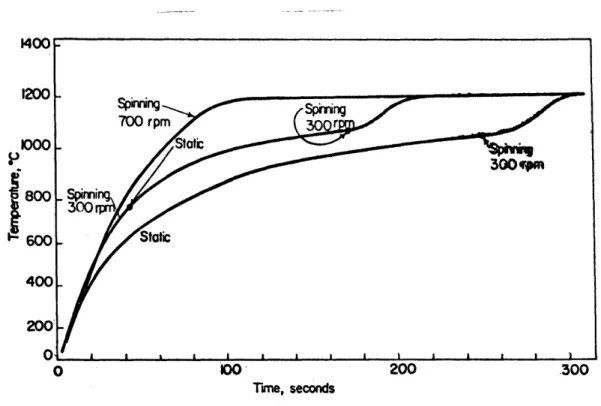
IV-1 Comparison of heating curves of a spinning
and a static sphere. Conditions: 3cm. nickel
sphere; slag N-IR, and bath temperature 13500C 61 IV-2 Comparison of heating curves of a sphere at
various spinning rates. Conditions: 3cm.
nickel sphere; slag N-IR; and bath temp. 13200C 61
IV-3 Comparison of heating curves of a small sphere at various spinning rates. Conditions: 1.8cm. nickel sphere; slag N-FB; and bath temp. 12500C 64 IV-4 Comparison of heating curves of a sphere at
various spinning and static conditions. Conditions: 3cm. nickel sphere; slag N-ICU;
and bath temperature 12000C 64
IV-5 Comparison of heating curves of a sphere under various types of convection. Conditions: 3cm. nickel sphere; slag N-ICU; and bath tem. 12000C 66 IV-6 Comparison of heating curves of a sphere in
slags N-IR, N-ICU, and N-2CU. Conditions:
3cm. nickel sphere; spinning at 700 rpm;
IV-7 Comparison of heating curves of a sphere in slags N-2W, N-FA, N-2W, and N-FB. Conditions: 3 cm. nickel sphere; spinning
at 700 rpm; and bath temperature 12500C. 68 IV-8 Comparison of the heating curves of a
sphere in slags N-FC, N-IA, N-2A, and N-CA. Conditions: 3cm. nickel sphere; spinning
at 700 rpm; and bath temperature 12500C. 68
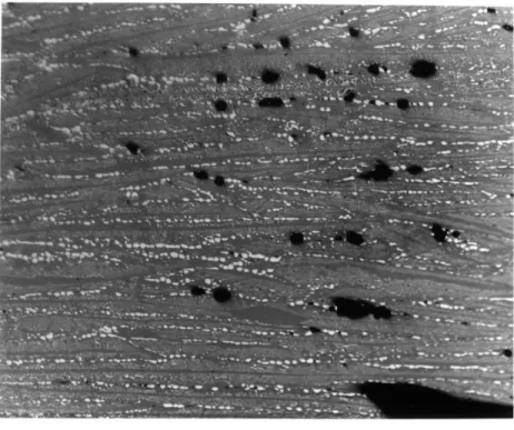
IV-9 Surface structure of slags N-FB and N-FA
from the solid slag shell. 69
IV-10 Microstructure of slag shell for slags N-FA
and N-FB (125x). 71
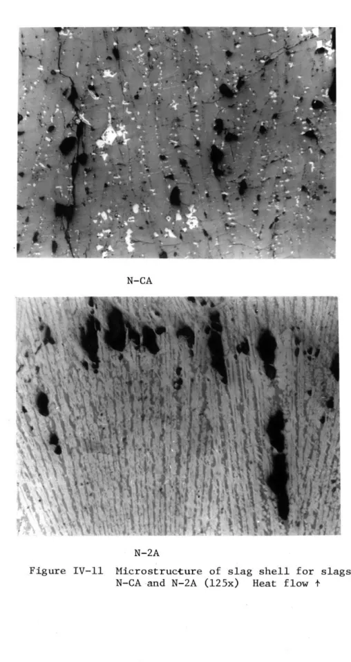
IV-ll Microstructure of slag shell for slags N-CA
and N-lA (125x) 72
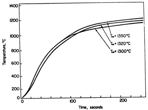
IV-12 Comparison of the heating curves of a static sphere at various bath temperatures.
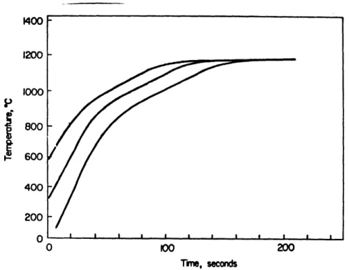
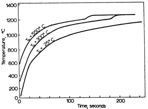
Con-ditions: 3cm. nickel sphere; and slag N-IR. 73 IV-13 Comparison of the heating curves of a spinning
sphere at various bath temperatures. Con-ditions: 3 cm. nickel sphere; spinning at
500 rpm; and slag N-IR. 73
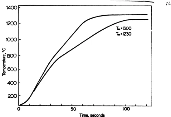
IV-14 Comparison of the heating curves of a spinning sphere at various bath temperatures. Con-ditions: 3cm. nickel sphere; spinning at
700 rpm; and slag N-FA. 74
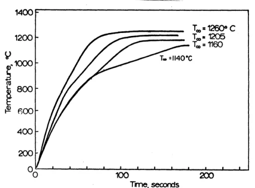
IV-15 Comparison of the heating curves of a
spinning sphere at various bath temperatures. Conditions: 3cm. nickel sphere; spinning at
700 rpm; and slag N-ICU. 74
IV-16 Comparison of the heating curves of a
spinning sphere at various bath temperatures. Conditions: 3cm. nickel sphere; spinning at
700 rpm; and slag N-FC. 75
IV-17 Comparison of the heating curves of a
spinning sphere at various bath temperatues. Conditions: 3cm. nickel sphere; spinning at 700 m~m: and 5l1.e N-2A,
10. LIST OF FIGURES (Cont'd.)
Figure Number Title Page
IV-18 Comparison of the heating curves of a sphere at various initial temperatures. Conditions: 3cm. nickel sphere; spinning at 700 rpm; bath temperature 11800C;
76 and slag N-ICU.
IV-19 Comparison of the heating curves of a sphere at various initial temperatures. Conditions: 3cm. nickel sphere; spinning at 700 rpm;
bath temperature 12500C; and slag N-FB. 77 IV-20 Comparison of the heating curves of a
sphere at various initial temperatures. Conditions: 3cm. nickel sphere; spinning at 700 rpm; bath temperature 12500C, and
slag N-lW. 77
IV-21 Comparison of the heating curves of a 3cm. sphere and a 1.8 cm. sphere. Conditions: spinning at 700 rpm; bath temperature
12500C; and slag N-FB. 79
IV-22 Comparison of the heating curves of a 3cm. nickel sphere and a 1.5 cm. nickel cylinder with the same volume. Conditions: spinning at 700 rpm; bath temperature 12000C; and
slag N-ICU. 79
IV-23 Comparison of the heating curves of a solid nickel sphere, a 50 mesh porous iron sphere, and a 100 mesh porous iron sphere. Con-ditions: 3cm. sphere; spinning at 700 rpm; bath temperature 12000C; and slag N-ICU
(and N-FC). 80
IV-24 Comparison of the heating curves of a copper sphere spinning in slag N-FC at 12500C and static in slag N-IR at 13300C. Conditions:
3 cm. copper sphere; and spinning at 700 rpm. 80 IV-25 Differential thermal analysis curves for
C I' an~r QlIon L~U~ UIIU L~ICLh~~
Figure Number Title Page V-I Finite elements for conduction in the alumina,
metal sphere, and the solid slag shell. 86 V-2 Liquid compositions for the solidification
of slag N-FB (72). 93
V-3 Temperature and composition distributions during melting and solidification of slag
N-FB with a planar interface. 94
V-4 Temperature and composition distributions during melting and solidification of slag
N-FB with a mushy interface. 97
V-5 Representations of a mushy front for
solidification and melting. 100
V-6 Relationship between the volumetric gas flow rate of a column of bubbles and the velocity
of the fluid drawn upward by the bubbles. 106
2 (PL-b) r bg
S 3 B
V-7 Heat transfer coefficients correlated to a dimensionless power number Np based on the experimental and theoretical work of Brian and Hales (16, 17). Dashed line represents the interpolated correlation for a slag with Npr = 150. Circles are the power numbers for the correlation that represent the
experimental conditions using Equation (31). 108 VI-I Overall heat transfer coefficients for
experiments with forced convection by rising bubbles (curves 4,5 and 6), spinning (curve 1), and natural convection (curve 1). Ex-perimental conditions are shown in Fig. IV-5. The dashed lines connect the same temperature of the sphere under the various conditions. 122
VI-2 Comparison between the calculated heating
curves using the model with the planar and
12.
LIST OF FIGURES (Cont'd.)
Figure Number Title Page
VI-3 Comparison between the experimental and calculated heating curves using a planar boundary condition. Experimental
con-ditions in Figure IV-7. 128
VI-4 Comparison between the experimental and calculated heating curves using a planar boundary condition at the melting point of fayalite 12050C. Experimental conditions
in Figure IV-21. 129
VI-5 Comparison between the experimental and calculated heating curves using a mushy boundary condition with a melting range 1170-12400C. Experimental conditions in
Figure IV-21. 129
VI-6 Comparison between the experimental and calculated heating curves using a planar boundary condition for slags N-FC, N-CA, and N-lA. Experimental conditions in
Figure IV-8. 132
VI-7 Comparison between the experimental and calculated heating curves using a planar boundary conditions for slags N-ICU and N-IR. Experimental conditions in Figure IV-6. 132 VI-8 Calculated effect of solidus fraction 0 on
the heating of the surface of a metal sphere. 134 VI-9 Comparison between the experimental and
cal-culated heating curves for slag N-2A at liquid at various liquid bath temperatures.
Ex-perimental conditions in Figure IV-17. 136 VI-10 Solid-liquid interface structures.
139 VI-11 Heat flow in cellular and mixed structures. 141 VI-12 Calculated thermal conductivity as a function
of volume fraction. 142
VI-13 Calculated thermal conductivity of porous slag at various values of porosity i and pore
LIST OF FIGURES (Cont'd.)
Figure Number Title Page
VI-14 Calculated effects of the heat transfer coefficient or Nusselt number on the heating of the metal sphere. Solidus
fraction 0.8. 147
VI-15 Calculated effects of the heat transfer coefficient or Nusselt number on the heating of the metal sphere. Solidus
fraction 0.95. 147
VI-16 Comparison between the experimental and calculated heating curves for a nickel cylinder and a nickel sphere. Experimental
conditions in Figure VI-22. 150
VI-17 Comparison between the experimental and calculated heating curves at various types of convection. Calculated heating curves for bubbling are based on power dissipation by the rising bubbles (see Section V.D.3.).
Experimental conditions in Figure IV-5. 150 VI-18 Comparison between the experimental and
calculated heating curves at various types
of convection. Calculated heating curves for bubbling are based on power dissipation by the rising bubbles (see Section V.D.3).
Experimental conditions in Figure IV-5. L52 VI-19 Comparison between the experimental and
calculated heating curves for a gas bubbling rate of 410 ml/sec. Calculated heating curve for bubbling is based on the velocity of the rising slag and a porosity in the
solid and liquid slag of 0.15. 152 VI-20 Pores in a slag shell sample after 50 seconds
of immersion. Cross section through the
thickness and across the shell (2x) 155 VI-21 Effective Nusselt number for a non-steady
state temperature distribution in the
14. LIST OF FIGURES (Cont'd.)
Figure Number Title Page
VI-22 Comparison between the experimental and calculated heating curves for a nickel sphere of various initial temperatures.
Experimental conditions in Figure IV-18. 162 VI-23 Calculated temperatures at the surface
and the center of a metal sphere with
various thermal diffusivity fractions 164 SM/aS.
VI-24 Comparison between the experimental and calculated heating curves for porous iron spheres. Experimental conditions
in Figure IV-23. 166
VI-25 Comparison between the experimeental and calculated heating curves for copper spheres. Experimental conditions in
Figure IV-24. 166
VII-1 Iron pellets at various stages of heating and melting in an electric furnace
steelmaking slag. 170
VII-2 Effects of two transients in the feeding rate M on thie number of pellets in the furnace N, the heat flow to the pellets
Q , and the temperature of the bath T . 174
VII-3 The calculated size and temperatures at the surface and the center of a thermally isolated pellet in an electric furnace as
a function of the time of immersion. 181 VII-4 Melting time of thermally isolated pellets
of various sizes and densities. 183 VII-5 Melting time of a porous pellet as a function
of beat transfer coefficient. 185
VII-6 Heat transfer coefficients for suspended particles in a fluid as a function of the power dissipation. Curve 1 is for thermal-ly isolated particles (17). Curve 2 is
Figure Number Title Page VII-7 Heat transfer coefficients for two
separated sphere as a fraction of the laminar flow rate and deparation
between the spheres (79). 189
A-1 Recorded response of a thermocouple with various forms of protection positioned at the center of a nickel sphere which
is heated in a radiation furnace. 199
B-1 Comparison between the temperature at the surface of a nickel sphere exposed to the slag and the surface attached to the nickel stem and iron tube. Calculated with the mathematical model assuming
perfect contact between the stem and the
tube. 202
B-2 Comparison between the temperature at the surface of a nickel sphere exposed to the slag and the surface attached to the nickel stem and iron tube. Calculated with the mathematical model assuming an
interfacial resistance between the stem
and the tube. 205
C-1 Temperature inside a 3cm. nickel sphere after 50 and 100 seconds of immersion
in a liquid slag at various bath
tem-peratures. 207
Radiating liquid bounded by a solid
16. LIST OF TERMS area of alumina cross-sectional surface area of surface area of surface area of surface area of sphere
area of bubble column
finite element i
metal sphere
iron pellet n in an electric furnace liquid-solid slag interface
C specific heat specific specific specific specific diameter diameter fraction fraction fraction gas flow heat of alumina heat of liquid slag heat of metal
heat of solid slag of a pore
of the sphere
of radiation heat flux in a boundary layer of slag solidifying at the liquidus temperature of slag solidifying at the solidus temperature rate CA CL C M CS d D rad fL f s F T hL hi K K K A K c
AA
Ac A. 1 AM A n A R view factorheat transfer coefficient in liquid slag interfacial resistance
thermal conductivity
thermal conductivity of non porous solid thermal conductivity of alumina
K thermal conductivity of in pore p
K thermal conductivity by photons r
KL thermal conductivity of liquid slag KM thermal conductivity of metal
KS thermal conductivity of solid slag
I. distance from the farthest temperature node to the moving boundary
L distance from the center of the sphere to the moving boundary
M mass feeding rate of iron pellets
N total number of pellets in an electric furnace NGr Grassoff number
NMo Morton number NNu Nusselt number
NNu power dissipation Nusselt number
Npr Prandlt number
N bubble Reynolds number
Re
NRe orifice Reynolds number
N spinning Reynolds number
Re s
NRe laminar flow Reynolds number
v
NWe Weber number q heat flux total
qc heat flux by conduction qr heat flux by radiation
Qs heat flow in boundary layer
r radial distance
r p R S t t m T T. T M T n T P T T s T U s U Vf Vb V. V X y
Q
c QE QL 18.radius of an iron pellet radius of the sphere
optical thickness
time
melting time temperature
temperature of finite element i at time j
temperature of metal
temperature of the surface of an iron pellet n
temperature in a pore
initial temperature of the sphere
temperature of the solid slag temperature of the bulk liquid Stokes velocity
overall heat transfer coefficient velocity of flowing fluid
velocity of rising bubble
volume of finite element i
volume of metal present horizontal distance vertical distance height of liquid slag
heat flow into a furnace by combustion
heat flow into a furnace from an electric arc heat loss from a furnace
w spinning frequency
teff effective thermal diffusivity of slag
aL thermal diffusivity of liquid slag
aM thermal diffusivity of metal
Cs thermal diffusivity of solid slag p linear coefficient of expansion
Y extinction coefficient
AH heat of fusion of the slag AH heat of fusion of the metal
m
AH enthalpy for heating and melting porous iron
AT DTA temperature difference between the reference and the sample
EA
total normal emissivity of aluminaENi
total normal emissivity of nickelE total normal emissivity of platinum p
t
ES total normal emissivity of solid slag 0 solidus fraction
o
dimensionless temperature A bulk absorption coefficientI viscosity
PL density of liquid slag
OPM density of metal
p density of porous iron p
p density of solid slag
20.
T dimensionless time
ý1 volume fraction of phase 1
#
2 volume fraction of phase 2
volume fraction of rising bubbles pore fraction
The author wishes to express his sincere appreciation to Professor John F. Elliott for his critical guidance and valuable discussions which were essential to the completeness of the work and the application of this investigation to practical conditions.
The author also wishes to thank Professors Warren R. Rosenhowe and Borivoje B. Mikic for their very helpful discussions on the
treatment of the heat transport equations in the presence of a moving boundary.
The National Science Foundation is gratefully acknowledged for
22.
I. INTRODUCTION
Silicate slags are important as heat transfer media in pyrometal-lurgical operations and fossil fuel fired boilers and turbines. Liquid slag transfers heat to particles of metal, flux, and oxides which are normally added during the refining in pyrometallurgical operations.
The slag becomes the sole source for heating and melting of the particles, when they become entrapped in the slag layer. Also, solid and liquid
slag which collect in boilers and turbines form barriers to the trans-fer of heat to the tubes and walls and provide a corrosive environment.
Several factors are important in the determination of heat transfer in silicate slags. The thermal conductivity of the slag is the most important of these factors. It depends upon the slag composition, temperature, and even the structure of the solid slag. The melting temperature of the slag, the convection in the liquid, and the proper-ties of other materials present in the immediate environment are also factors in the heat transfer in silicate slags.
The purpose of the present investigation is to analyze the heat transfer from a liquid slag to a cold metal particle. The investiga-tion is divided into two stages. First, in a specially designed
laboratory experiment, the effects of the slag composition, the liquid slag temperature, the convection in the liquid, and the composition in the metal sphere are measured. Then a mathematical model is developed which simulates the heat transfer to a cold metal particle immersed in a liquid slag. This mathematical model uses the available data on the
thermal properties of the silicate slags and various boundary conditions for the solidification and melting of the slag on the metal particle.
The experimental results and the mathematical model are compared to analyze the effects of the thermal conductivity of the slag, the convection in the liquid slag, the solidification and melting of the slag, and the properties of the metal particle. The mathematical model is also modified to simulate the melting of prereduced iron particles in an electric furnace slag.
24.
II. LITERATURE SURVEY
There are three general areas which are essential for this study of heat transfer in silicate slags: 1) measurements of the thermal conduc-tivity and thermal diffusivity of liquid and solid slag, 2) practical heat transfer problems encountered in the use of silicate slags for metallurgical refining and coal combustion, and 3) mathematical models of heat transfer associated with a moving boundary.
II.A. Thermal Properties of Slag
Relatively few measurements of thermal conductivity and bulk radia-tion transport for silicate slags are available. These measurements indicate the factors which control heat transfer and directly apply to heat transfer in the slags in which the measurements were made. Radiation transport may be especially important for silicate slags
because they are semi-transparent and allow substantial heat transfer by photons in the liquid and glassy states.
Fine and Elliott (1, 3) measured the thermal diffusivity and radia-tion transport of several liquid synthetic steelmaking slags. Using a cylindrical slag sample, the thermal diffusivity was obtained by
measuring the phase shift between a periodic current impressed on a wire at the center of the sample and the temperature response at the outer wall. They measured the thermal diffusivity at various concentrations of iron oxide and various lime to silica ratios. Most of these slags were prepared at iron saturation and had very low concentrations of ferric
equal to 1.0 and 1.5 were represented by the Equation (1)
(T/1500)
aeff = 0.001 (1.5-0.5B) + 0.018 (T/.500) 0.8 (1) wt.% CaO B = T < 17500K wt.% SiO2with an error of 10%. Apparently the thermal diffusivity decreases with increasing wt.% FeO because of decreasing radiation transport in the bulk of the slag. The effect of lime to silica ratio, B, on the effective thermal diffusivity was traced to the probable increase in the mean free path, L, for photon and phonon conduction as the viscosity of the slag was reduced by the addition of lime.
Fine and Elliott (1, 3) suggested that the radiation contribution to transport in these iron oxide slags was of the same order as the con-duction contribution (phonon concon-duction). The transport of thermal radiation in a semi-transparent medium affects the temperature distri-bution, depending upon the optical thickness of the specimen. The optical thickness is defined
s = Xx (2)
where
A
is the bulk absoption coefficient and x is the thickness of the specimen. If the optical thickness of the specimen is greater than about 4, then the thermal radiation contribution to the conduction can besimply added to the phonon conduction to constitute an "effective" thermal conductivity. The apparatus used by Fine and Elliott was designed so that the specimens were sufficiently optically thick for the measurements of "effective" thermal diffusivity.
26.
Thermal radiation through a semi-transparent specimen may also be important in determining heat transfer at a phase boundary. The absorption of thermal radiation at a solid boundary in a liquid glass specimen was modeled and measured at a steady state by Eryou and Glicksman (74). A non-linear temperature distribution in the glass and an increase in the heat flux at the boundary was observed, which depended upon the magnitude of the bulk absorption coefficient in the glass. The bulk absorption
coefficient for glassy slags at 0 to 14% FeO concentrations was measured by Fine and Elliott (3). The scattering coefficient for polycrystalline slags also limits the transport of thermal radiation through a specimen. In most cases the scattering coefficient is several orders of magnitude greater than the bulk absorption coefficient.
More recent measurements with the periodic steady state apparatus, reported by Nauman, Foo and Elliott (4) of ferrous silicates and synthetic
copper smelting slags, indicated no general relationship between slag composition and effective thermal diffusivity. The thermal diffusivity of the solid slag was also measured in the periodic source apparatus. The typical value of thermal diffusivity of a ferrous silicate, composed principally of fayalite, was 0.0042 cm2/sec. This value applied for the
liquid as well as the solid slag. The effect of radiation on the heat transfer in these slags was not appreciable due to the very high con-centration of FeO (50.1 to 69.5%). All of these slags were prepared at iron saturation.
Braun (13) measured the thermal conductivity of several coal ash slags with a calibrated thermal gradient technique. These slags were
obtained from a slagging boiler and contained 20 to 64.4 wt.% Fe2033
Under various oxygen pressures, which attempted to simulate boiler conditions, the conductivity increased with exposure to oxidizing
atmosphere. This increase was probably due to the oxidation of ferrous iron to the ferric state.
Gibby and Bates (6) measured the thermal diffusivity of basalt using a high temperature laser pulse technique. Similar to other measu-rements on terrestrial rock (5), the thermal diffusivity decreased with increasing temperature near the melting point. A value of about 0.0045 cm /sec. was recorded for a liquid basalt about 1400%C.
Using the same laser pulse technique, Bates (7) measured the thermal diffusivity of several synthetic and real power plant coal ash slags.
His measurements indicated that the diffusivity of the solid slag decreased with increasing temperature. This contradicts the measurements made by
Braun in which the thermal conductivity of solid coal ash increased with increasing temperature. Also Bates' measurements demonstrated that slags of nearly identical compositions have distinctly different thermal
diffusivities. The only explanation given for the different diffusivities was that the degree of crystallization and heat treatment seemed to have
an effect. The microstructure of these nearly identical slags may have been quite different, but there is insufficient information presented to asses this.
In general, the thermal diffusivity from available data on silicate slags ranges from 0.003 to 0.007 cm2/sec. for both the high temperature
28.
solid and liquid. The works of Bates and Braun demonstrated that solid slags which have similar compositions may not exhibit the same thermal conductivity of thermal diffusivity, if the slags are given different treatments.
II.B. Practical Slag Heat Transfer
There are several practical processes in metallurgical operations and electric power generation where heat transfer in the slag is critical. Some of these processes are electric furnace steelmaking with reduced iron pellets, electroslag remelting, strand casting with a slag flux, coal fired boilers, and open cycle magnetohydrodynamic generators.
The continuous charging of reduced iron pellets into an electric furnace may be limited by heat transfer in the refining slag layer within the furnace. Many of the present day reduced pellets have densities less than that of the refining slag, and the melting of these pellets is accomplished almost entirely within the slag layer. Sibakin et al. (14) reported that such a practice with reduced iron pellets was feasible, if precautions were taken to minimize the freezing of slag and pellets into "islands". Formation of these islands was greatly affected by the
distribution of pellets in the furnace and convection in the liquid slag.
In the electroslag remelting process, heat transfer in the slag is extremely critical for melting to electrode and solidification of the ingot in the copper mold. Heating in this process is primarily by joule heating of the slag contained between the electrode and the formed ingot. Mitchell and Joshi (15) determined that among the most important factors controlling
the heat generation in the remelting of an ingot were the electrical and thermal properties of the slag. Also the depth of the liquid metal pool and thus the solidification of the ingot depended upon the thermal insu-lation by the layer of slag that forms on the ingot.
In boilers which are fired with coal, slag forms from the ash on the fire side of the tube walls. This slag increases the resistance of the walls to heat flow, so the burner temperature must be increased to maintain the operation of the boiler. At the higher temperatures the flow of heat through the slag is irregular because there are variations in the thickness of the slag and the radiation properties of the surface (57). A thin layer of slag or a large radiation absorption results in catastrophic tube wall temperatures (68, 69). Similarly, in the tech-nology of open cycle magnetohydrodynamic power systems, the thermal properties of the ash and slag become critical. At wall temperatures below 17000C, Bogdanska et al. (12) reported that a significant quantity of slag condenses. The condensation and freezing of slag was controlled by heat transfer in the walls and slag. It was found that the slag coating on the electrodes and insulators caused severe corrosion of oxide elec-trodes and insulators, while actually protecting the metal elecelec-trodes. Therefore the presence of the condensed layer of slag can be very critical to the operation of the generator.
II.C. Heat Transfer at a Phase Boundary
Liquid slag solidifies on the surfaces of cold metal particles refractory tubes, and walls in practical operations. With the presence of solids and liquids, heat transfer in these systems involves a moving
30.
solid-liquid phase boundary accompanied by absorption or release of the enthalpy of fusion. The heat balance at the moving boundary is given by
dX
S
dX
s dt
where KL and KS are the thermal conductivities of the liqfid and the
solid slag, respectively; ps is the density of the solid slag, AH is the enthalpy of fusion; and dL is the change in the thickness of the solid slag. The temperature at this boundary may be fixed at a melting
temperature; it may reflect under cooling during solidification or over-heating during melting; or, since most slags melt over a range, the boundary temperature may vary over this melting range.
Mathematical models of heat transfer in the presence of a moving boundary and flowing liquids have been investigated only for specific conditions as yet. The exact solutions due to Stefan and Newmann (22) apply to the more elementary problems of solidification of a stationary liquid at the melting temperature, bounded by a plane wall at a constant temperature. Goodman's integral method has been applied assuming soli-dification on a plane wall of uniform and constant temperature, and assuming constant heat flux from the liquid to the solid phase (23, 24, 26, 27). Variational methods, such as those developed by Biot and Green
(28, 29) have been applied to moving boundary problems for cylindrical and spherical walls. However, the evaluation of the integrals in all of these methods presents considerable difficulties when dealing with problems of solidification and convection in the liquid boundary layer. Also,
according to the investigations by Megerlin (75), the Goodman integral method does not yield very accurate results in problems of melting
solidification.
Numerical methods can become very complex due to the nonlinear boundary conditions for heat flux at the phase boundary. The usual procedure is to estimate the thickness of the solid layer, then to determine the temperature distribution, which provdes a new value for the thickness of the layer (33, 34). Several numerical methods have also been proposed which lump together the specific heat and the enthalpy of
fusion at the melting temperature of the materials (30, 31, 32, 35). In these methods the moving interface is never actually defined.
A further survey of the previous work on mathematical models and convection in the liquid, which apply directly to the present experimental study, is included in Chapter V on mathematical modeling.
32.
III. EXPERIMENTAL
In this chapter the design and the procedure of the laboratory experiments for the study of heat transfer in silicate slags are des-cribed. The principal laboratory experiments consisted of immersing a cold metal sphere in a "semi-infinite" liquid slag. The metal sphere enters the slag at a predetermined temperature, and the temperature at the center of the sphere is measured continuously. From this continuous measurement of temperature it is possible to determine the transfer of heat from the slag to the sphere as a function of time. During this experiment the flow of liquid slag was controlled by spinning the sphere, or holding the sphere static and stirring with rising gas bubbles. The experiments were conducted in different compositions of liquid slag at various temperatures. The metal objects which were immersed into the liquid slag were nickel spheres, nickel cylinders, copper spheres, and porous iron spheres.
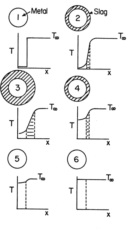
During the immersion of the metal sphere into the liquid slag, the slag solidifies around the cold sphere and then melts away as shown in Figure III-1. Stage 1 shows the sphere and the slag at constant temperatures upon the initial immersion. Stage 2 shows the slag shell solidifying on the sphere, and the temperature distribution within the sphere as it begins to heat. Stages 3 and 4 show the slag
shell at a maximum thickness and as it begins to melt. After the slag shell is completely remelted, stages 5 and 6 show the sphere continuing to heat to the slag bath temperature. Heat transfer in such a system is
Q
Metal
Slag
1w
0
Q
Figure III-1 Six stages of heating a cold metal sphere in a liquid slag
34.
determined by the thermal properties of the metal sphere, the solid slag, and the convection in the liquid.
The melting range of the slags studied was measured by differential thermal analysis. This melting range was necessary for the mathematical model which is described in Chapter V.
III.A. Preparations for Experiments
III.A.1. Preparation of the Slag
The slags were prepared for these experiments by mixing toget1er reagent grade powders of pure oxides to obtain the compositions shown in Table III-1. After mixing the powders for 10 to 20 hours by tumbling, the mixture was charged into an iron crucible and melted. The iron
crucible consisted of a 21 cm. section of a 6 inch diameter steel tube (0.7 wall thickness) which was closed on the bottom by a 1/2 inch steel plate welded to the tube. On the top of this iron crucible was placed a lid of 1/4 inch steel plate with a 5 cm. hole in the center. This lid prevented the formation of a solid slag crust on the top of
the liquid.
The crucible was surrounded by bubble grain alumina and high
temperature refractory brick as shown in Figure 111-2. Heat was applied to the iron crucible by an induction furnace (Tocco Meltmaster, 50KVAR, 9720 Hertz). When an optical pyrometer sighted on the inside wall of
the crucible, the temperature was increased to 100C above the melting temperature of the slag mixture. This temperature was held constant until most of the mixture became liquid, and then more powder was stirred
Slag Total Fe N-2W 60.2
(60.1)
N-FA 59.2 (58.9) N-lW 58.1(58.1)
N-FB 54.7 (54.7) N-FC 47.6 (48.6) N-lA 43.2 (43.5) N-2A 39.3 (40.3) N-CA 43.2 (43.1) N-1CU 32.8 (35.2) N-2CU 38.5 (40.2) N-IR 11.0 Found by analysis FeO 74.4 73.5 72.9 69.5 60.5 55.1 50.1 55.1 40.5 45.5 14.2 Fe203 3.2 3.0 2.6 1.8 1.4 1.2 1.1 1.2 5.0 5.0 SiO 2 22.4 23.5 24.6 28.7 38.1 34.7 31.5 34.6 40.5 35.5 31.4CaO Al203 Other
9.0 17.3 9.1 7.0 5.0 7.0 5.0 31.4 12.5 1.0 MgO; 1.0 S 1.0 MgO; 1.0 S 10.5 MgO Description
wustite saturation, near the fayalite-wustite peritectic
Fayalite-wustite peritectic
Fayalite saturation, near
the fayalite-wustite peritectic Fayalite (Fe2SiO4)
Fayalite-silicate peritectic
N-FC + 9% Al203 N-FC + 18% Al203 N-FC + 9% CaO
high silica synthetic copper smelting slag
high FeO synthetic copper smelting slag
synthetic steelmaking
as described in Appendices C and G.
36.
Thmrwvvvv WAM6
'ucible
FON
ite
MgO
crucible)
Figure 111-2 Experimental furnace for heat transfer measurements
I I
~I
I hLJ7A
in and melted to obtain a liquid slag of 14 cm. depth. Before starting any experiments the liquid slag was kept at a constant temperature for 30 to 40 minutes. The single charge could be reused for several
experiments.
Because of the higher working temperatures for slag N-IR (1300-1400'C), a MgO crucible (1.4 cm. wall thickness) was used instead of the
iron crucible. Heat was provided by a 1.5 cm. thick graphite susceptor surrounding the MgO crucible. A 3 cm. thick graphite lid with a 5 cm. hole in the center prevented the formation of a slag crust on the top of the liquid.
Samples of the slag were taken from the liquid and analyzed for total iron to check the expected composition (see Appendix G).
III.A.2. Preparation of the Metal Spheres
The nickel and copper spheres were prepared by investment casting, while the porous iron spheres were prepared by sintering iron powder.
The spherical patterns for the investment molds were made in the following manner. Standard ball bearings of 1 1/4, 1, and 3/4 inch diameter were mounted separately on wax pedestals. They were then surrounded by silicone rubber (Allied Resin Co., RTV 664). After the silicone rubber hardened (24 hours) the ball bearings were removed by carefully cutting along a vertical cross-section of the rubber block with a sharp knife. By leaving a portion of the rubber uncut, the rubber mold could be reassembled and filled with wax.
38.
These spherical wax patterns were then used to make lost wax investment molds. A pattern was attached to a cylindrical wax stem which was 0.8 cm. in diameter and 1.0 cm. long. Two or three of these assemblies were then attached to a cylindrical riser which was 3.0 cm. in diameter and 6 cm. long, as suggested by Taylor et al. (64). A 0.8 cm. diameter runner and a 1.0 cm. diameter sprue were fitted to the bottom of the riser, and would funnel the liquid metal into the riser during pouring. The entire wax pattern was inverted on a metal into the riser during pouring. The entire wax pattern was inverted on a metal plate, and surrounded with a section of steel pipe. Ferrous investment material (Ransom and Randolf 711) was mixed, 10 parts to 1 part water, and poured around the wax pattern. The green mold was then vibrated to eliminate gas bubbles.
After setting overnight, the green mold was removed from the plate and placed in a furnace at 1000C for 4 to 12 hours to remove the wax. The temperature of the mold was then increased at a rate of 100 to 200 degrees per hour to reach 9000
C. At this temperature the investment mold was allowed to burn clean, set, and reach a steady temperature. Then the mold was removed from the furnace and was ready for casting.
For the nickel castings, pure nickel shot was melted inductively and brought to 15500C in a dense MgO crucible (15.2 cm. deep and 1 cm. wall thickness). The temperature was monitored by an optical pyrometer. To deoxidize the melt, 1 to 2 grams of aluminum were added just before the nickel was poured into the hot investment mold. For the copper
castings, electrical grade copper was melted in a graphite crucible which was heated inductively. Argon was bubbled into the melt for 3 minutes prior to casting to help purge oxygen from the copper. The copper was poured at 11500C.
The nickel and copper castings were removed from the investment after 4 to 8 hours of cooling. The stem of each sphere was cut close to the riser to remove the sphere. The stem was machined to fit into the iron tube (5/16 inch inside diameter) as shown in Figure 111-2, and the hole for the thermocouple was drilled to the center of the sphere.
While mounted in a lathe the surface of the sphere was lightly sanded and polished with 320 emery paper. Later, the sphere and hole were cleaned with acetone.
The porous iron spheres were sintered using the ferrous investment molds, but in a different configuration. Spherical wax patterns were made from the silicone rubber molds of 3.0 cm. diameter, with cylindrical
stems 2.5 cm. long. The spheres with stems were mounted vertically on a metal plate and cast in the ferrous investment material. After the investment was set as described above, the investment mold was removed from the furnace and filled with either 50 mesh iron filings or 100 mesh iron powder. Then iron tubes (5/16" outside diameter 3/16"inside and 2.5 cm. diameter long)were pressed into the iron filings, such that 0.5 cm. of the iron tube extended into the spherical cavity of the investment mold. The tube was carefully centered, straightened, and packed securely in the filings. A small amount of graphite powder was spread on top of the iron filings and the mold to minimize the oxidation during
40.
Table 111-2. Properties of Metal Spheres
Metal Nickel Nickel Copper Iron (50 mesh) Iron (100 mesh) See Section V.F. Thermal Diameter Density Diffusivity
-m. g/cm3 cm2/sec. 3.06 1.83 3.06 3.06 8.2 8.2 8.7 3.8 4.5 3.06 0.14 0.14 0.90 Specific heat (cal/ g-OC 0.13 0.13 0.11 At 8000C
ouple
.ction
Tube
e
al Sphere
Foil
Figure 111-3 Metal sphere and iron support tube
-Iron
42.
sintering. The mold was placed in the furnace and heated to 9000C. After three hours at 9000C the mold was removed and allowed to cool. The sintered spheres were removed very carefully and cleaned. As with
the copper and nickel spheres, a 0.3 cm. hole for the thermocouple was drilled carefully into the sphere.
The densities of the metal spheres were calculated from the weight and the size of the spheres and stems. Values at room temperature are given in Table 111-2., along with other properties. The estimation of
the thermal diffusivity of the porous iron sphere is discussed in Section V.F.
The thermocouple which was inserted into the metal sphere shown in Figure III-3 was a platinum platinum-10% rhodium couple of 10 mil wire.
In the experiments with slag N-IR, the thermocouple was protected by a 0.1 cm. thick alumina protection tube. In the experiments with all other slags, the thermocouple bead was protected by platinum foil which was placed in direct contact with the metal sphere. The effects of the
protection on the response of the thermocouple are discussed in Appendix A.
The iron tube which supported the sphere was 60 cm. long and 1.2 cm. in diameter. At the bottom end of the iron tube, the metal sphere was held in place with two set screws. The thermocouple wires, which were
protected by an alumina insulator, ran from the sphere and along the inside of the tube. The tube was mounted in ball bearing pillow blocks which were fixed to the transite carriage as shown in Figure 111-4.
Figure 111-4 Transite carriage supporting the DC motor, pillow block bearings and the slip rings and brushes for the spinning tube and sphere
44.
Along with these pillow blocks, a DC motor and a set of electrical contacting brushes were mounted on the carriage. The metal brushes were in contact with two copper slip rings which were connected to the thermocouple wires at the top of the iron tube. These contacting brushes and slip rings allowed the tube and sphere to spin freely about their vertical axis without disturbing the output of the thermo-couple.
III.B. Heat Transfer Experiments in Liquid Slag
The experimental conditions for the heat transfer experiments with liquid slag are shown in Table III-3.
III.B.1. Forced Convection by Spinning
Heat transfer experiments were conducted in liquid slag with spinning nickel spheres. Forced convection by spinning produces the conditions of flow which are shown in Figure 111-5 (11). The fluid flows vertically toward the sphere at the poles and proceeds spirally along the surface to the equator. There an outward jet forms in the shape of an equatorial plate. Under the conditions of the present experiments in liquid slags, the flow along the surface of the sphere is laminar, based on the empirical criteria (11)
2
wD 5
p L< 10
where w is the spinning frequency; D is the diameter of the sphere;
PL is the density of the liquid; and p is the viscosity of the liquid slag.
Table 111-3. EXPERIMENTAL CONDITIONS Slag
Run No. Temperature (oC) Convection Slag N-Fa N-FB 6C 4A 4B 4C 4D 4E 4F 4G 19C 19D 19E IOA lOB 1OC 1OD 2A 2B 2C 3A 3B 3C 3D 3E 1OF 15A 15B 11A 11B 11C 19A 19B 20A 20B 20C 20D 11D 6A 6B 0 rpm 700 rpm 700 rpm 700 rpm 900 rpm 900 rpm 700 rpm 0 rpm 310 rpm 710 rpm 680 rpm 930 rpm 700 rpm 700 rpm 700 rpm 1250 1250 1250 1310 1250 1250 1200 1220 1220 1220 1220 1220 1250 1250 1250 1200 1245 1275 1240 1240 1230 1230 1200 1220 1240 1230 1225 1220 1170 1170 1205 1260 1250 1140 1200 1240 1240 1240 rpm rpm rpm rpm rpm rpm rpm rpm rpm rpm rpm rpm rpm rpm rpm rpm rpm rpm rpm rpm 700 rpm 700 rpm 700 rom Metal Ni (3cm) Ni (3cm) Ni (3cm) Ni (3cm) Ni (3cm) Ni (3cm) Ni (3cm) Ni (1.8cm) Ni (1.8cm) Ni (1.8cm) Ni (1.8cm) Ni (1.8cm) Ni (3cm)
(3000C)
(5500oC)
Ni (3cm) Ni (3cm) Ni (3cm) Ni (3cm) Ni (3cm) Fe (50 mesh) Cu Ni (3cm) Ni (3cm) Ni (3cm) Ni (3cm) Ni (3cm) Ni (3cm) Ni (3cm) Ni (3cm) Ni (3cm) Ni (3cm) Ni (3cm) Ni (3cm) Ni (3cm) Ni (3cm) Ni (3cm) Ni (3cm) 700 700 700 700 700 700 700 700 700 700 700 700 700 700 700 700 700 700 700 700 N-FC N-1A N-2A N-CA46.
Table 111-3. EXPERIMENTAL CONDITIONS (Cont'd.)
Slag
Slag Run No. Temperature (oC) 19C 9C 9D N-2CU 17A 17B 17C 17D 17E 17F 17G N-lW N-2W N-IR 15C 15D 15E 15F 15G 7A 7B 7C 12A 12B 12C 12D 8A 8B 8C 8D 21A 21B 21C 21D 21E 21F 1240 1140 1150 1120 1130 1210 1230 1220 1220 1200 1230 1230 1230 1240 1250 1150 1170 1200 1360 1360 1340 1350 1350 1340 1350 1400 1300 1350 1390 1360 1380 1350 Convection 700 rpm 700 rpm 700 rpm 700 rpm 700 rpm 700 r~m 50 cm /sec 300 cm3/sec static 700 rpm 700 rpm 700 rpm 700 rpm 700 rpm 700 rpm 700 rpm 600 rpm 600 rpm 330 rpm 550 rpm 700 rpm 900 rpm 500 rpm 700 rpm static static static static static static Metal Ni (3cm) (5500C) (3000C) Ni (3cm) Ni (3cm) Ni (3cm) Ni (3cm) Ni (3cm) Ni (3cm) Ni (3cm) Ni (3cm) (5000C) Ni (3cm) Ni (3cm) (3cm) (3cm) (3cm) (3cm) (3cm) (3cm) (3cm) (3cm) (3cm) (3cm) (3cm) (3cm) (3cm) (3cm) (3cm) (3cm) (3cm)
Table 111-3. EXPERIMENTAL CONDITIONS (Cont'd.)
Slag Run No.
Slag
Temperature (oC) Convection 700 rpm 700 rpm 700 rpm 700 rpm 700 rpm 700 rpm 700 rpm 700 rpm 700 rpm 700 rpm 0-300 rpm 300-0 rpm 700 rpm 700 rpm 700 rpm 700 rpm 700 rpm 40 cm3/sec 250 cm3/sec 410 cm3/sec 330 cm3/sec Ni Ni Ni Ni Ni Ni Ni Ni Ni Ni Ni Ni Ni Ni Ni Fe Fe Ni Ni Ni Ni (3cm) (3cm) (3cm) (3cm) (3cm) (3cm) (3cm) (3cm) (3cm) (3cm) (3cm) (3cm) cylinder (3cm) (3cm) (100 mesh) (50 mesh) (3cm) (3cm) (3cm) (3cm) N-ICU Metal 18A 9A 9B 13A 13B 14A 14B 14C 14D 14E 18B 18C 16A 16B 16C 16D 16E 181) 18E 18F 16F 1.200 1150 1150 1160 1200 1210 1240 1300 1300 1230 1200 1200 1160 1180 1200 1200 1200 1200 1200 1200 11200
48.
Figure 111-5 Fluid flow about a spinning sphere, arrows indicate streamlines
It will be shown in Section V.D. that heat transfer coefficients for forced convection by spinning can be determined from empirical correlations. Also, in Section VI.D.3. it will be shown that the temperature distribution in the liquid boundary layer of a spinning sphere reaches a steady state very quickly. Both the heat transfer coefficient and the steady temperature distribution in the boundary layer are essential to the calculations in the mathematical model which is presented in Chapter V.
Heat transfer experiments involving spinning were conducted in the following manner. The thermocouple was positioned at the center of the 3 cm. nickel sphere, which was attached to the iron tube. Then the
iron tube was mounted in the pillow block bearings shown in Figure 111-4, and the slip rings and brushes were connected. After the liquid slag in the crucible shown in Figure 111-2 remained at temperature, the temperature was measured with an optical pyrometer. The slag was stirred by hand with an iron rod to improve the uniformity of the temperature of the slag. Using the controlled DC motor, the spinning velocity (revolutions per minute) of the sphere and tube assembly was set at a particular value as noted in Table 111-2. This velocity was measured with a stroboscopic tachometer before immersing the sphere
into the slag. After starting the millivolt recorder, the spinning metal sphere was immersed into the liquid slag by manually lowering the transite carriage along two vertical metal tracks located just above the furnace. The carriage was quickly lowered until the center of the sphere was 7 cm. beneath the surface of the liquid slag. The spinning
50.
velocity was again measured with the tachometer, and the temperature of the liquid was measured with an optical pyrometer, which was sighted on the surface of the slag. The metal sphere remained immersed in the liquid slag until the temperature recorded by the thermocouple at the center of the sphere indicated no further change. At this time, the electric motor was shut off, and the sphere and assembly were removed from the furnace.
Usually the sphere and assembly could be reused, after the iron tube was checked for straightness, and the metal sphere was cleaned off and allowed to cool to room temperature. Often the tube could be
straightened, if it became bent. Some metal spheres were used for as many as eight separate experiments.
The errors which are inherent in this experiment are discussed in Appendices A, B and C.
III.B.2. Forced Convection by Bubble Stirring
The purposes of conducting heat transfer experiments in silicate slags stirred by rising bubbles were to test another form of convection in the slag, and to simulate practical mixing conditions in an electric furnace steelmaking operation. Bubbling was a good alternative method of convection because it was less severe than spinning, yet direct enough for estimating heat transfer coefficients in the liquid. Also, bubbling is the predominant means by which the slag is stirred during electric furnace steelmaking operations.
The procedure for the experiments which used stirring by rising bubbles was similar to that for the experiments which used the spinning
sphere. A horizontal iron tube provided the flow of gas bubbles in the experiment as shown in Figure 111-6. This iron tube was 5 cm. long and 1.2 cm. in diameter with 24 1 mm. orifices on the upper one fourth of its surface. Nitrogen gas flowed into this bubbling tube from another 1.2 cm. iron tube, rising vertically through the top of the crucible shown in Figure VII-6. The flow of nitrogen was measured by a mercury manometer and a capillary flowmeter. As shown in Table 111-3 the range
of flow rates was 0 to 410 cm 3/sec. Only slags N-lCU and N-2CU were used in these experiments.
After the slag was completely melted inside the iron crucible, the bubbling tube was lowered through the hole in the top of the lid,
immersed into the liquid slag, and set at the bottom of the crucible. Gas flowed through the orifices of the bubbling tube until the
tempera-ture of the slag and the tubing reached a steady state. Once this steady state was achieved at a set gas flow rate, the nickel sphere (not spinning) was quickly immersed into the liquid slag and fixed in position immediately above the column of rising bubbles. The
tempera-ture at the center of the sphere was recorded as a function of time after immersion until the temperature reached a steady value. All other procedures were identical to those with the sphere spinning, Section III.B.1.
52.
sphere
bubbles
bubbling tube
III.B.3. Experiments with Various Slag Compositions
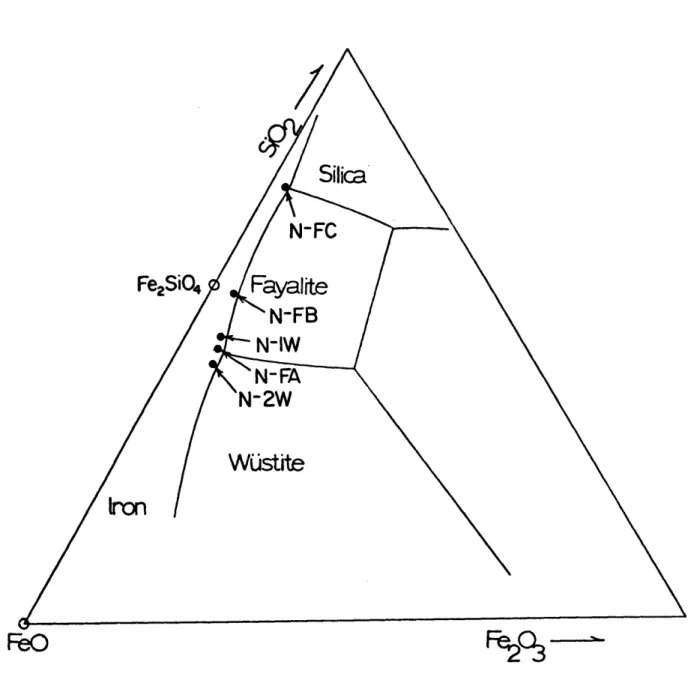
Several different types of slags were studied under the conditions outlined in Table 111-2. The chemical compositions and descriptions of these slags are given in Table III-1. For the ferrous silicate slags, N-1W, N-FA, N-2W, N-FB, and N-FC, the locations of the
compositions are shown in the polythermal projection of the liquidus of the FeO-Fe203-SiO2 system in Figure 111-7. The measured and
estimated properties of some of these slags are shown in Table 111-4 and 111-5. The sources of these values are discussed in detail in Section V.E.
III.B.4. Experiments with Various Metal Objects
The purpose of using various metal objects in these heat transfer experiments was to assess the effects of 1) the initial temperature of the metal object, 2) the size of the metal object, 3) the shape of
the object, 4) the thermal conductivity of the metal, and 5) the melting of the object.
The initial temperature of the spinning nickel sphere was varied by preheating the sphere above the furnace before immersing it into the liquid slag. The initial temperature of the sphere in Table 111-2 was obtained by heating the nickel sphere 10 to 20 degrees above the pre-determined initial temperature and then placing it inside a refractory shield to cool uniformly. Once the initial temperature was obtained, the spinning sphere was immersed into the slag and the normal experimental procedures were followed.
Table 111-4. Thermal Properties of Liquid Slags at Iron Saturation
Symbol Specific heat, cal/g oC
Density, g/cm3 Thermal diffusivity (cm /sec x 104 ) Thermal conductivity cal/sec-cm-oC x 10 Viscosity, poise
Linear coefficient of thermal expansion, /oC x 106 CL OL N-FA 0.28 3.8 N-FB 0.28 3.7 47. 40. 48. 41. 1.5 2. l 50 50. N-F 0.2 3.6 Slag Designation 'C N-lA N-2A 8 0.28 0.28 3.5 3.5 52. 32. 52. 31. 2. 2. N-CA 0.28 3.5 N-ICU 0.28 3.5 N-IR 0.28 2.9 32. 53. 47. 40. 31. 53. 47. 32 2. 2. 2. 5. 50. 50. 50. 50. 50. 50.
See Section V.E.1 for complete references
---
~---Table 111-5. Thermal Properties of Solid Slags
Symbol N-FA N-FB N-FC N-lA N-2A N-CA N-ICU N-IR
Specific heat, cal/g-0 C CS 0.24 0.25 0.25 0.25 0.25 0.25 0.25 0.24
Density, g/cm3 pS 4.3 4.2 3.7 3.8 3.8 3.9 3.8 2.9
Thermal diffusivity, cm2/sec x 104 aS 51. 47. 64. 37. 37. 48. 45. 40.
Thermal conductity,
cal/sec-cm-OC x 104 KS 52. 44. 59. 35. 35. 47. 43. 28.
Solidus temperature, oC TS 1152. 1170. 1150. 1070. 1070. 1060. 1125. 1230.
Heat of fusion, cal/g AH 110. 115. 80. 80. 80. 80. 80. 130.
See Section V.E.2 for complete references See Section IV.B.
56.
The following metal objects were studied in the heat transfer experiments: 1) nickel and copper spheres of 3.06 cm. diameter, 2) nickel spheres of 1.8 cm. diameter, and 3) a nickel cylinder of 1.5 cm. diameter and 8.8 cm. length. The conditions for these experiments are shown in Table 111-2. In the case of the copper sphere, the copper melted was allowed to fall to the bottom of the crucible.
Some heat transfer experiments were conducted with porous iron spheres as described in Section III.A.2. These experiments simulated the heat transfer to low thermal conductivity porous iron pellets used in electric furnace operations. The experimental conditions are shown in Table 111-2. Procedures were identical to those used for a spinning sphere.
III.C. Differential Thermal Analysis of Slags
The melting temperature for the solidified slag shell was determined by differential thermal analysis. A 20 mg. sample of powdered slag was placed inside an iron crucible (1.4 mm. inside diameter) as shown in Figure 111-8. A 20 mg. reference of Baker reagent grade alumina was placed in an identical iron crucible. Positioned in a K-28 firebrick which was surrounded by a graphite susceptor, these crucibles were heated to a temperature 500C below the suspected solidus. Then the heating rate was adjusted to 10 degrees per minute and the temperature was raised through the melting temperature of the slag. During the melting, a platinum/platinum-l0% rhodium thermocouple which was in direct contact with the powdered slag recorded the temperature of the
Fi~O4
Figure 111-7 FeO-SiO2-Fe203 phase diagram for ferrous silicate slags (72)
58.
be
nduction
coils
Thermocouples
Iron crucibles
Graphite
K-28 brick
Slog
sample
Differential thermal analysis apparatus
0
0
O,
0
0
O
Figure 111-8slag. The temperature of the slag was plotted against the temperature difference between the slag and the alumina to indicate the presence of phase changes.
This differential thermal analysis technique was tested with samples of KC1. Cooling as well as heating DTA curves were recorded with some of the samples of slag to test the measurement of the melting range. The slag samples for the analysis were obtained from the solid slag
shell formed on the nickel sphere after 30 seconds of immersion in the particular liquid slag.