Development of a Pointing, Acquisition, and
Tracking System for a Nanosatellite Laser
Communications Module
by
Kathleen Michelle Riesing
B.S.E., Princeton University (2013)
Submitted to the Department of Aeronautics and Astronautics
in partial fulfillment of the requirements for the degree of
Master of Science in Aeronautics and Astronautics
at the
MASSACHUSETTS INSTITUTE OF TECHNOLOGY
September 2015
c
○ Massachusetts Institute of Technology 2015. All rights reserved.
Author . . . .
Department of Aeronautics and Astronautics
August 20, 2015
Certified by . . . .
Kerri L. Cahoy
Assistant Professor of Aeronautics and Astronautics
Thesis Supervisor
Accepted by . . . .
Paulo C. Lozano
Associate Professor of Aeronautics and Astronautics
Graduate Committee Chair
Development of a Pointing, Acquisition, and Tracking System
for a Nanosatellite Laser Communications Module
by
Kathleen Michelle Riesing
Submitted to the Department of Aeronautics and Astronautics on August 20, 2015, in partial fulfillment of the
requirements for the degree of
Master of Science in Aeronautics and Astronautics
Abstract
Launch opportunities for small satellites are rapidly growing and their technical capa-bilities are improving. Several commercial constellations of small satellites for Earth imaging and scientific observation are making their way onto orbit, increasing the need for high bandwidth data downlink. Obtaining regulatory licensing for current radio frequency (RF) communications systems is difficult, and state of the art nanosatel-lite RF systems struggle to keep up with the higher demand. Laser communications (lasercom) has the potential to achieve high bandwidth with a reduction in power and size compared to RF, while simultaneously avoiding the significant regulatory burden of RF spectrum allocation.
Due to narrow beamwidths, the primary challenge of lasercom is the high-precision pointing required to align the transmitter and receiver. While lasercom has been suc-cessfully demonstrated on multiple spacecraft platforms, it has not yet been demon-strated on a scale small enough to meet the size, weight, and power constraints for nanosatellites. The Nanosatellite Optical Downlink Experiment (NODE) developed at MIT is designed to achieve a lasercom downlink of 10 to 100 Mbps within the constraints of a typical 3-U CubeSat.
This thesis focuses on the development of the pointing, acquisition, and tracking system for NODE. The key to achieving a high bandwidth downlink is to bridge the gap between existing CubeSat attitude determination and control capabilities and the narrow beamwidths of lasercom. We present a two-stage pointing control system to achieve this. An uplink beacon and detector provide fine attitude feedback to enable precision pointing, and CubeSat body pointing is augmented with a fine steering mechanism.
The architecture of the pointing, acquisition, and tracking system is presented, followed by the in-depth design and hardware selection. A detailed simulation of the ground tracking performance is developed, including novel on-orbit calibration algorithms to eliminate misalignment between the transmitter and receiver. A testbed is developed to characterize the selected fine steering mechanism for performance and thermal stability. The proposed system is capable of achieving at least two
orders of magnitude better pointing than existing CubeSats to enable high bandwidth nanosatellite downlinks.
Thesis Supervisor: Kerri L. Cahoy
Acknowledgments
I would first like to thank my advisor Kerri Cahoy. Beyond technical guidance, she is an excellent role model and has provided me incredible opportunities in my time at MIT. I look forward to continuing on for my PhD.
A special thank you to my parents: to my dad, for inspiring me to be an engineer and fostering my intellectual curiosity, and to my mom for providing the support and continual encouragement to make it through to the other side. To my brother, whom I always strive to surpass and will not allow to be the only doctor in the family. Thank you to all the friends who have helped me along the way. In particular, Britta Kelley, David Sternberg, and Margaret Tam have kept me smiling through many rough patches.
This project would not have been possible without the contributions of graduate students Ryan Kingsbury and Tam Nguyen. Thank you for motivating discussions and filling in the gaps in my knowledge. I would also like to thank undergraduates Hang Woon Lee and Derek Barnes for their work on the project.
This project was supported by a JPL Strategic University Research Partnership (SURP). This work was also supported by a NASA Space Technology Research Fel-lowship under grant #NNX14AL61H.
Contents
1 Introduction 21
1.1 Motivation for a Nanosatellite Laser Communications System . . . . 21
1.2 Laser Communications Background & Challenges . . . 24
1.2.1 Pointing, Acquisition & Tracking Subsystem . . . 25
1.2.2 Overview of Prior Missions . . . 29
1.3 Nanosatellite Attitude Determination & Control Background . . . 33
1.3.1 Three-axis-stabilized CubeSat Missions . . . 33
1.3.2 Commercial-Off-The-Shelf Hardware . . . 35
1.4 Nanosatellite Laser Communications . . . 37
1.4.1 Key Challenges & Existing Efforts . . . 37
1.4.2 NODE Concept of Operations . . . 39
1.5 Thesis Objective & Roadmap . . . 40
2 Pointing, Acquisition & Tracking Approach 43 2.1 NODE System Overview . . . 43
2.1.1 Design Approach & Key Requirements . . . 43
2.1.2 Summary of Key Parameters . . . 46
2.2 Pointing, Acquisition, & Tracking Architecture . . . 47
2.2.1 Concept of Operations . . . 48
2.2.2 Single-Stage vs. Two-Stage Design . . . 49
2.2.3 Monostatic vs. Bistatic Design . . . 53
2.2.4 Hybrid Laser & Radio Calibration Method . . . 55
2.3.1 Host Spacecraft Performance . . . 57
2.3.2 Fine Steering Requirements . . . 57
2.3.3 Beacon Detector Requirements . . . 58
2.3.4 On-orbit Calibration Requirements . . . 59
2.4 Fine Stage Hardware . . . 59
2.4.1 Layout . . . 60
2.4.2 Beacon Detector . . . 61
2.4.3 Fast Steering Mirror . . . 61
3 Simulation Analysis & Results 65 3.1 Ground Tracking Simulation . . . 65
3.1.1 Motivation & Overview . . . 66
3.1.2 Dynamic Models . . . 69
3.1.3 Sensor Models . . . 74
3.1.4 Actuator Models . . . 75
3.1.5 Control & Estimation Models . . . 77
3.1.6 Pointing & Tracking Results . . . 82
3.2 Post-Acquisition Calibration Simulation . . . 85
3.2.1 Motivation & Overview . . . 86
3.2.2 Description of Algorithms . . . 87
3.2.3 Noise & Error Models . . . 89
3.2.4 Calibration Results . . . 93
4 Fast Steering Mirror Characterization & Results 97 4.1 Fast-Steering Mirror Testbed . . . 97
4.1.1 Components & Layout . . . 98
4.1.2 Thermal Test Environment . . . 99
4.2 Description of Tests . . . 100
4.2.1 Comparison to Fixed Mirror . . . 101
4.2.2 Response to High Voltage Enable . . . 101
4.2.4 Position Repeatability . . . 102 4.2.5 Thermal Conditions . . . 103 4.3 Test Results . . . 104 4.3.1 Device Hysteresis . . . 105 4.3.2 Zero Position . . . 106 4.3.3 Device Sensitivity . . . 109 4.3.4 Position Repeatability . . . 110 4.3.5 Summary . . . 111 5 Conclusion 115 5.1 Thesis Summary . . . 115 5.2 Thesis Contributions . . . 117 5.3 Future Work . . . 117
List of Figures
1-1 Nanosatellite market projection [1]. . . 22
1-2 Absorption of the electromagnetic spectrum in the Earth’s atmosphere [2]. . . 24
1-3 Typical lasercom pointing, acquisition, and tracking sequence. . . 26
1-4 Point-ahead angle as a function of relative velocity. . . 27
1-5 Generic block diagram for PAT subsystem [3]. . . 29
1-6 LCT 2nd generation, the backbone of the EDRS [4]. . . 31
1-7 Rendering of LLCD inertially stabilized telescope [5]. . . 32
1-8 Reaction wheels developed by Sinclair Interplanetary for CanX-2 [6]. 34 1-9 Rendering of OCSD [7]. . . 38
1-10 NODE hybrid RF and optical architecture. . . 40
2-1 NODE requirements flowdown. . . 44
2-2 Functional block diagram of NODE. . . 46
2-3 Histogram of CubeSat orbital altitudes from 2010-2014. . . 47
2-4 Concept of operations for pointing, acquisition, and tracking on NODE. 49 2-5 Pointing loss as a function of pointing error (requirement shown in gray). 50 2-6 Block diagram of monostatic and bistatic architectures. . . 53
2-7 Angular magnification with beam reduction. Off-axis incoming light (green) as compared to on-axis light (red) for reference. . . 55
2-8 Hybrid laser downlink and radio uplink calibration concept. . . 56
2-9 NODE hardware layout. . . 60
2-11 NODE fine stage MEMS fast-steering mirror. . . 63
3-1 RSW satellite reference frame [8]. . . 66
3-2 Pitch maneuver for ground tracking. . . 67
3-3 Atmospheric density as a function of altitude. . . 68
3-4 Block diagram of tracking simulation. . . 69
3-5 MiRaTA 3-U CubeSat used for modeling the host spacecraft [9]. . . . 70
3-6 Geometry of pitch angle and angle of elevation with ground station in orbit plane. . . 71
3-7 Bode plot of FSM response data and transfer function model. . . 77
3-8 Environmental disturbance torques for ground tracking maneuvers at 400 km. . . 83
3-9 Coarse and fine stage pointing error with beacon feedback and com-pensation for environmental disturbances. . . 84
3-10 Receiver power as a function of slant range, normalized to peak power. 90 3-11 Probability density function of effect of atmospheric scintillation on downlink power. . . 91
3-12 Mitigation of atmospheric scintillation with time-averaged power mea-surements (𝑡𝑎𝑣𝑔 = 100𝑡𝑑). . . 93
3-13 Example of calibration performance for uncertain search and compass search. . . 94
3-14 Normalized histogram of Monte Carlo (N=1000) calibration results for compass search and uncertain search. . . 95
4-1 Testbed used for FSM characterization. . . 98
4-2 Geometry of FSM testbed. . . 99
4-3 Thermal chamber setup for FSM characterization. . . 100
4-4 Commanded FSM voltages for X axis sweep. . . 102
4-5 Commanded voltages for 5-sided die repeatability pattern. . . 103
4-6 Ramp and soak profile #1 used for testing FSM response. . . 104 4-7 Ramp and soak profile #2 used for testing FSM thermal deformation. 105
4-8 X-axis response hysteresis in FSM device S4045. . . 106 4-9 No hysteresis in response of FSM devices S4044 and S4043. . . 106 4-10 Thermally-induced angular shift of testbed setup with fixed mirror. . 107 4-11 Thermally-induced angular shift of FSM devices calibrated against
fixed mirror. . . 108 4-12 Angular shift of FSM devices on HV enable. . . 110 4-13 Error in 5th order polynomial fit to voltage sweep data at 20 ∘C for
S4044, showing an increase in device sensitivity at low temperature. . 111 4-14 Tip/tilt repeatability of S4044 in random dice pattern. . . 112
List of Tables
1.1 Summary of major free-space lasercom missions. . . 30
1.2 Key design parameters for LCT and LLCD systems. . . 31
1.3 Summary of key three-axis-stabilized nanosatellite missions. . . 34
1.4 Control modes for the OCSD mission. . . 39
2.1 Summary of key parameters of NODE. . . 48
2.2 Comparison of key parameters for OCSD and NODE. . . 52
2.3 Host spacecraft performance requirements for compatibility with NODE. 57 2.4 NODE fine steering requirements. . . 58
2.5 NODE beacon detector requirements. . . 59
2.6 NODE on-orbit calibration requirements. . . 59
2.7 Commercial focal plane array options for beacon detector. . . 61
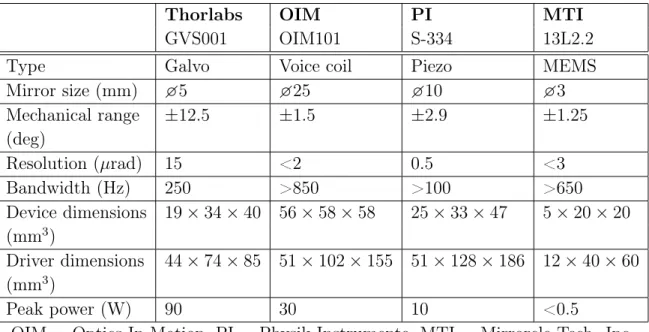
2.8 Commercial fast-steering mirror performance and operational charac-teristics. . . 63
3.1 Simulation parameters for beacon detector. . . 74
3.2 Simulation parameters for gyroscope. . . 75
3.3 Simulation parameters for reaction wheel. . . 76
3.4 Simulation parameters for FSM. . . 76
3.5 Simulation results of tracking performance of fine and coarse stages. . 84
3.6 Effect of sources of error (added incrementally) on ground tracking performance. . . 85
Nomenclature
ADCS Attitude determination and control subsystem ALEX Airborne Lasercom Experiment
APD Avalanche photodiode BCT Blue Canyon Technologies BRITE Bright Target Explorer
CanX Canadian Advanced Nanospace Experiment CMOS Complementary metal-oxide-semiconductor COTS Commercial-off-the-shelf
DIP Dual in-line package DOF Degree of freedom
EDRS European Data Relay Satellite System ESA European Space Agency
FOV Field of view FPA Focal plane array
FWHM Full width at half maximum Gbps Gigabits per second
GEO Geosynchronous Earth orbit
GeoLITE Geosynchronous Lightweight Technology Experiment GPS Global Positioning System
HV High voltage
IMU Inertial measurement unit IR Infrared
ISL Intersatellite link
ISS International Space Station
JAXA Japanese Aerospace Exploration Agency JPL Jet Propulsion Laboratory
LCT Laser Communication Terminal LEO Low Earth orbit
LLCD Lunar Laser Communication Demonstration LOS Line of sight
LUCE Laser Utilizing Communications Experiment MAI Maryland Aerospace, Inc.
Mbps Megabits per second
MEMS Microelectromechanical systems MIT Massachusetts Institute of Technology MPE Maximum permitted exposure
NASA National Aeronautics and Space Administration NODE Nanosatellite Optical Downlink Experiment NRL Naval Research Laboratory
Chapter 1
Introduction
Space-based laser communications (lasercom) has the potential to transform scien-tific, defense, and commercial spacecraft communications platforms. Compared with traditional radio frequency (RF) communications, lasercom offers higher bandwidth, reduced size and mass of transceivers, lower power consumption, and also avoids the significant regulatory hurdles of radio frequency allocation. Nanosatellites in partic-ular have great potential to benefit from lasercom as they are heavily constrained in size, weight, and power (SWaP). The Nanosatellite Optical Downlink Experiment (NODE) is a 10 × 10 × 5 cm3 module targeting a >10 Mbps downlink that is being
developed at the MIT Space Telecommunications, Astronomy, and Radiation Labora-tory (STAR Lab) [10]. This thesis focuses on the pointing, acquisition, and tracking (PAT) subsystem design for NODE.
1.1
Motivation for a Nanosatellite Laser
Communi-cations System
Nanosatellites are a class of small satellites with a mass between 1-10 km. The most common type of nanosatellite is the CubeSat. The CubeSat first emerged in 1999 as an academic exercise to design a very small satellite [11]. A CubeSat is a miniaturized satellite that is measured in segments called “U”s. Each U measures 10 × 10 × 10 cm3
and weighs no more than 1.33 kg. The CubeSat was ideal for academic use since it allowed students to work with space-bound hardware without the long timelines of large satellite projects. Since 1999, the CubeSat has become a popular standard for rideshare opportunities. When a large satellite is launched, extra space in the launch vehicle can be filled with deployers designed to match CubeSat standards.
The CubeSat market is currently experiencing a period of rapid growth. While CubeSats were designed for primarily academic use, a significant increase in commer-cial activity has led to the expansion of the CubeSat market shown in Figure 1-1. Thousands of nanosatellites are predicted to launch before 2020, with Earth obser-vation and remote sensing satellites leading this trend [1]. Two Earth obserobser-vation start-ups, Planet Labs and Spire, have led the commercial trend and plan to deploy major constellations. Spire has launched four CubeSats to date, with plans to deploy 20 by the end of 2015 and 100 by the end of 2017 [12]. Planet Labs has successfully launched 101 satellites despite the loss of 26 satellites in the Antares rocket failure in 2014, and has plans to launch hundreds more [13, 14].
Figure 1-1: Nanosatellite market projection [1].
As the number of satellites in orbit grows, the rate of data generation puts pressure on existing RF communications infrastructure, particularly as low latency downlink
is a priority for many commercial companies. The communications subsystem has long been a limitation for CubeSats. The time required to license a portion of the RF spectrum often takes longer than the entire time to design, build, and test the satel-lite [15]. The amateur band is becoming overcrowded with CubeSats and licensing organizations such as the Federal Communications Commission (FCC) are straining to keep up with increased demand [16].
Operators requiring high-speed data rates must use higher frequency bands for which there is little available commercial hardware. Commercial options offer data rates up to 5 megabits per second (Mbps), and other academic and commercial op-erators have developed custom solutions [17, 18]. The existing communications bot-tleneck will continue to worsen as more nanosatellites enter into orbit. Development of commercial high-rate RF radios can provide the hardware to support high-rate communications. However, this will present even more of a challenge for the licensing of the overcrowded RF spectrum. A high-rate, scalable communications solution for CubeSats is needed.
The near-infrared spectrum utilized in lasercom has few regulations. Unlike RF, lasercom spectrum does not require official allocation to use because the small beamwidths present little risk of interference. The only restrictions for lasercom fre-quencies are focused on safety. The American National Standards Institute (ANSI) provides a metric for the maximum permitted exposure (MPE), which limits the power flux (in W/cm2) of the signal and is dependent on wavelength [19]. For laser-com downlinks, transmitted power is spread out over a large area and does not ap-proach the MPE limit. Safety limits must be considered on uplink since the power is concentrated on the ground, but careful design can avoid the MPE without too much difficulty.
Given the fundamental limitation of available RF bandwidth, a lasercom solution for nanosatellites is an attractive option. High-gain apertures allow reductions in SWaP while supporting high-rate communication. More importantly, the lasercom spectrum is nearly unregulated and enough bandwidth is available to meet commu-nications needs well into the future.
1.2
Laser Communications Background & Challenges
There are two major bands of the electromagnetic spectrum that pass through the Earth’s atmosphere with very little attenuation. One of these bands is located in the radio frequency spectrum and the other includes wavelengths near the visible portion of the spectrum, as shown in Figure 1-2. Laser communications utilize wavelengths in the near-infrared (near-IR) region of the spectrum.
Figure 1-2: Absorption of the electromagnetic spectrum in the Earth’s atmosphere [2].
The high carrier frequency of lasercom offers a significant advantage in link effi-ciency [20]. This can be seen in a simplified version of the link equation:
𝑃𝑅𝑥 ∝
𝑃𝑇 𝑥𝐴𝑇 𝑥𝐴𝑅𝑥
𝜆2𝑅2 (1.1)
where 𝑃𝑅𝑥 is received power (W), 𝑃𝑇 𝑥 is transmitted power (W), 𝐴𝑇 𝑥 is transmitter
area (m2), 𝐴𝑅𝑥 is receiver area (m2), 𝜆 is wavelength (m), and 𝑅 is distance between
transmitter and receiver (m). Received power scales with the inverse square of the wavelength. RF wavelengths range from 1 m in the UHF band down to 7.5 mm in the
K𝑎-band. In contrast, lasercom wavelengths are typically between 0.8-1.6 microns.
The result is that lasercom can achieve higher bandwidth communications with re-duced volume, mass, and power. In fact, the entire bandwidth of the RF spectrum could fit into just a small window in the near-IR portion utilized for lasercom.
However, the benefits of lasercom also come with a unique set of challenges. The first major challenge of lasercom is atmospheric loss. Lasercom frequencies are very susceptible to atmospheric effects. Absorption and scattering cause attenuation losses, and atmospheric turbulence produces variations in signal phase, intensity, and direc-tion [21]. Atmospheric effects can be mitigated by ground station diversity, and optimization studies have focused on site selection [22–24]. While single-site avail-ability ranges from 60-80%, a combination of three or more sites can achieve over 90% availability [25].
The second major challenge of lasercom is the pointing, acquisition, and tracking (PAT) subsystem. While narrow transmit beamwidths increase lasercom link effi-ciency, the tradeoff is the need for very precise PAT. This topic is covered in detail in section 1.2.1. The primary aim of this thesis is developing a lasercom PAT subsystem that addresses this challenge and is compatible with current nanosatellite technology.
1.2.1
Pointing, Acquisition & Tracking Subsystem
Lasercom systems must align the optical line-of-sight (LOS) very precisely, with typ-ical systems requiring error as small as submicroradians [3]. Usually this cannot be achieved by the spacecraft bus alone, so multiple stages of sensors and actuators are required. The coarse sensors have a wider field of view (FOV) to acquire the uplink beacon and the coarse actuators have a large range at the expense of resolution. The fine sensors have a narrow FOV to enable precision pointing by the fine actuators. The stages of control must be coordinated for handoff such that the range of one stage overlaps with the resolution of the stage that precedes it. The most capable lasercom systems may have four or more stages of actuation to achieve the pointing accuracy required for communications [5, 26].
shown in Figure 1-3. The vast majority of lasercom systems use beacon tracking to locate the ground station. In this approach, the ground station sends up a wide beam at a predetermined wavelength towards the spacecraft. The spacecraft, expecting this signal, can then reorient towards the beacon to improve its pointing. While beacon-less tracking reduces system complexity and is particularly appealing for deep space lasercom, it is extremely challenging to implement in practice [27]. The PAT sequence described here is specific to beacon tracking. Step 1 describes initial pointing, steps 2-3 follow the acquisition of the ground beacon, and steps 4-5 describe ground station tracking. Together these make up the pointing, acquisition, and tracking segments.
Figure 1-3: Typical lasercom pointing, acquisition, and tracking sequence.
Initial conditions for the spacecraft consist of orbital and pointing knowledge. The sequence begins with initial pointing towards the expected location of the ground station. Orbital knowledge usually comes from GPS, radar tracking, or two-line element sets (TLEs), and any error in the spacecraft’s position is translated into mispointing. The mispointing induced by position error gets worse the closer the spacecraft is to the ground station. Pointing knowledge also induces error as the spacecraft relies on a combination of gyroscopes, magnetometers, accelerometers, sun sensors, Earth horizon sensors, or star trackers to determine its orientation with
limited accuracy.
The spacecraft then enters steps 2 and 3, the acquisition sequence. After the spacecraft points at the predicted location of the ground station, it uses wide FOV sensors and coarse actuators to scan for the ground station beacon. Once the beacon has been detected, the spacecraft can close its tracking loop around the beacon and reduce pointing error. The spacecraft transitions from open-loop tracking to closed-loop tracking. The spacecraft maintains the beacon within the fine sensor FOV which enables high bandwidth feedback control. Handoff occurs from the coarse to the fine stage to achieve the accuracy required for communications.
After acquisition, steps 4-5 describe the tracking segment. The spacecraft has closed its tracking loop around fine sensors and fine actuators, but one additional step is needed for downlink. The spacecraft has a relative velocity with respect to the ground station, which means that its position changes during the time-of-flight of the signal between the two terminals. Therefore, a point-ahead/look-behind angle is needed to correct for the expected location of the terminal as shown in Figure 1-4.
Figure 1-4: Point-ahead angle as a function of relative velocity.
The point-ahead angle depends only on the relative velocity between the terminals and can be derived geometrically from Figure 1-4. Using a small angle approximation and simple geometry, the point ahead angle becomes:
𝜃 ≈ 2𝑉𝑟𝑒𝑙
𝑐 (1.2)
where 𝑉𝑟𝑒𝑙 is the relative velocity between the terminals and 𝑐 is the speed of light.
For the ground station, this correction points ahead in the spacecraft trajectory. For the spacecraft terminal, the correction has the same magnitude but looks behind in its trajectory.
The final step is link maintenance which is conducted throughout communica-tions. The purpose of link maintenance is to ensure transmit/receive (Tx/Rx) path alignment. This can be done by slightly nutating pointing angle and applying a cor-rection based on received power at the opposing terminal. Alternatively, the system can be designed with self-test capabilities through the use optical elements to redirect transmitted signal into the receive path for periodic alignment.
Figure 1-5 shows a generic block diagram for a PAT subsystem [3]. The most com-mon coarse actuators are gimbals since they have a large range. Typical fine pointing actuators are tip/tilt fast-steering mirrors (FSM) and linear stages to adjust position on the receive and transmit fibers. Adjusting the position of the fiber adjusts the Tx/Rx angle, which is a technique known as nutation tracking. Another fine steering technique is the use of an inertially stabilized platform, which has linear actuators to adjust the orientation of a telescope/optical assembly and actively dampen vibra-tional disturbances [5]. To implement the point-ahead angle described by Equation 1.2, a point-ahead mirror or nutation of the Tx fiber is commonly used.
Lasercom links from low Earth orbit (LEO) to ground present several unique challenges for PAT. The satellite will have to slew rapidly to track the ground station, placing stress on the attitude determination and control subsystem. The point-ahead angle given in Equation 1.2 will be relatively large due to high orbital velocities. Finally, ground station passes will last less than 10 minutes, so the PAT subsystem must quickly acquire and track the ground station to maximize data transmission.
Figure 1-5: Generic block diagram for PAT subsystem [3].
1.2.2
Overview of Prior Missions
While early lasercom missions demonstrated feasibility, recent missions have focused on developing optimal, high bandwidth systems with low SWaP. Table 1.1 summarizes some key historical and recent missions [5, 20, 26, 28–30], highlighting the increase in system capabilities as well as the diversity of global participants. Links have been successfully demonstrated between terminals in geosynchronous orbit (GEO), low Earth orbit (LEO), airplanes, ground, and the moon.
In particular, two state-of-the-art missions highlight the current capabilities of lasercom systems and also provide insight into PAT subsystem design. The first is the Laser Communication Terminal (LCT) developed by Tesat Spacecom of Germany, and the second is the Lunar Laser Communication Demonstration (LLCD) developed jointly by NASA and MIT Lincoln Laboratory. Key design parameters for these missions are summarized in Table 1.2.
LCT is a lasercom terminal design that has been reused on multiple missions. The first LCT was demonstrated on the Semiconductor-laser Inter-satellite Link Exper-iment (SILEX) in 2001 between satellites in LEO and GEO. Additional LCTs were developed for LEO satellites NFIRE and TerraSAR-X, launched in 2007, as well as
Table 1.1: Summary of major free-space lasercom missions. Year Mission Organization Link Type Data Rate
(Gbps) 2001 GeoLITE/ MIT Lincoln GEO-ground/ >1
ALEX Laboratory GEO-air
2001 SILEX ESA LEO-GEO 0.05 2005 LUCE JAXA LEO-GEO 0.05
LEO-ground
2008 NFIRE/ Tesat Spacecom LEO-LEO 5.65 TerraSAR-X LEO-ground
2013 LLCD MIT Lincoln Moon-ground 0.622 Laboratory/NASA
2014 OPALS JPL ISS-ground 0.05 2014 EDRS Tesat Spacecom/ LEO-GEO 1.8
ESA GEO-ground
for an accompanying optical ground station. NFIRE and TerraSAR-X conducted an intersatellite link (ISL) and LEO-ground link at 5.65 Gbps, the highest rate published as yet [26].
Based on these successes, European Space Agency (ESA) has embarked on de-veloping the European Data Relay Satellite System (EDRS). EDRS will consist of a constellation of GEO satellites to relay data between LEO satellites and ground stations that relies on the 2nd generation LCT as the backbone [31]. LCT 2nd gen-eration, shown in Figure 1-6, successfully demonstrated a 1.8 Gbps link between Alphasat in GEO and Sentinel-1 in LEO in late 2014 [32].
The PAT subsystem of LCT consists of 4 stages (i.e. 4 independent actuators for pointing). The coarse stage consists of a two-axis gimbal assembly with hemispherical coverage [4, 33]. The next stage is a coarse steering mirror immediately following the aperture. There is an additional fine pointing mirror, and finally a mirror dedicated to point-ahead implementation on the downlink. Altogether, the actuators consist of a two-axis gimbal assembly and three tip/tilt mirrors which enable an RMS pointing accuracy of 100 𝜇rad [34].
Table 1.2: Key design parameters for LCT and LLCD systems. LCT (2nd Gen.) LLCD Link type LEO-GEO-ground Moon-ground Tx wavelength (nm) 1064 1550 Data rate (Gbps) 1.8 0.622 Range (km) >45000 >380000 Tx power (W) 2.2 0.5 Aperture (cm) 13.5 10.8 Mass (kg) 56 30 Power consumption (W) 160 100 # of PAT stages 4 4
RMS pointing accuracy (𝜇rad) 100 2.5
Figure 1-6: LCT 2nd generation, the backbone of the EDRS [4].
The second state-of-the-art mission highlighted here is the Lunar Laser Commu-nication System (LLCD) developed jointly by MIT Lincoln Laboratory and NASA. LLCD was launched in September 2013 as a technology demonstration on the Lunar Atmosphere and Dust Environment Explorer (LADEE). LLCD successfully demon-strated a 622 Mbps lasercom link from lunar orbit, which is the furthest link range demonstrated to date. LLCD’s data rate was six times faster than prior lunar RF communications at half the weight and one quarter the power consumption [7].
body pointing. While this is not strictly part of the LLCD system, the host space-craft has a pointing requirement of 100 𝜇rad RMS in each axis to support LLCD [5]. Whereas LCT had a hemispherical gimbal assembly enabling some degree of auton-omy from the host spacecraft, LLCD relies on LADEE’s body pointing for initial alignment. LLCD also includes a two-axis gimbal assembly to execute coarse adjust-ments. Both the Tx and Rx fibers have two-axis linear stages. For the Rx fiber, the stage enables nutation tracking of the uplink signal, and the Tx stage implements the point-ahead angle for the downlink. This entire assembly rests on a two-axis inertially stabilized platform used for fine positioning, pictured in Figure 1-7. The overall pointing accuracy is within 2.5 𝜇rad [5].
Figure 1-7: Rendering of LLCD inertially stabilized telescope [5].
Future missions are planned with involvement from both the public and private sector [31, 35]. The successful demonstrations thus far have targeted a much larger class of satellites than CubeSats, with the existing terminals ranging from 30-150 kg and consuming >100 W of power. A 3-U CubeSat measuring 10 × 10 × 34 cm3 weighs
no more than 4 kg and typically consumes only 10-20 W. While lasercom technology is advancing greatly, the challenge of developing a lasercom terminal to meet the needs of nanosatellites has not yet been addressed.
1.3
Nanosatellite Attitude Determination & Control
Background
The attitude determination and control subsystem (ADCS) for nanosatellites has improved tremendously in recent years. Early CubeSats had no attitude control and simply tumbled or relied on spin or gravity gradient stabilization [11]. Three-axis stabilized CubeSats have been made possible by the development of commercial-off-the-shelf (COTS) ADCS components, particularly the miniaturization of reaction wheels [36]. Attitude knowledge has long been a limiting factor for nanosatellite ADCS but the development and integration of small sensors, particularly star trackers, is rapidly improving capabilities.
1.3.1
Three-axis-stabilized CubeSat Missions
Nanosatellites, which range between 1-10 kg, are the smallest satellites currently ca-pable of three-axis-stabilized pointing. Table 1.3 summarizes key missions advancing the state of the art in nanosatellite ADCS [6, 37–43].
The first nanosatellite to achieve three-axis stabilization was SNAP-1, developed at the University of Surrey and launched in 2010. SNAP-1 ADCS consisted of a magnetometer, three-axis magnetorquers, and a single momentum wheel. With only a magnetometer, orientation around the B-field vector cannot be resolved, so a large momentum bias was used to compensate for the absence of full three-axis attitude knowledge. The satellite experienced a 1.5∘ bias in both roll and yaw but maintained pointing within 3∘ (1-𝜎) in these axis, resulting in an overall pointing accuracy within about 15∘ (3-𝜎) [37]. SNAP-1 was a major milestone in demonstrating nanosatellite three-axis stabilization, particularly given the limited ADCS hardware.
Two major players emerged in the development of three-axis-stabilized nanosatel-lites. The Space Flight Laboratory at the University of Toronto Institute for Aerospace Studies (UTIAS-SFL) developed CanX-2, an early three-axis-stabilized CubeSat [6]. For CanX-2, UTIAS-SFL developed a custom suite of six sun sensors and a three-axis
Table 1.3: Summary of key three-axis-stabilized nanosatellite missions. Year Mission Organization Size Bus Pointing
Accuracy 2001 SNAP-1 Surrey Space 6.5 kg * 15∘ (3-𝜎)
Centre 2008 CanX-2 UTIAS-SFL 10 × 10 × 34 cm3 2∘ (1-𝜎) 2010 QbX NRL 10 × 10 × 34 cm3 5∘ (3-𝜎) 2011 PSSCT-2 The Aerospace 13 × 13 × 26 cm3 15∘ (3-𝜎) Corporation
2012 AeroCube-4 The Aerospace 10 × 10 × 10 cm3 3∘ (3-𝜎)
Corporation
2013 BRITE UTIAS-SFL 20 × 20 × 20 cm3 0.015∘
(1-𝜎) *Dimensions not available.
magnetometer. A reaction wheel developed jointly with Sinclair Interplanetary was used for momentum bias in a similar approach to SNAP-1. The reaction wheels, shown in Figure 1-8, were a major step forward in the development of COTS com-ponents for CubeSat ADCS. CanX-2 achieved attitude determination accuracy to around 1.5∘ (1-𝜎), allowing control to approximately 2∘ (1-𝜎).
Figure 1-8: Reaction wheels developed by Sinclair Interplanetary for CanX-2 [6].
UTIAS-SFL went on to develop the Bright Target Explorer (BRITE) constellation mission, which consists of six 20 × 20 × 20 cm3 nanosatellites dedicated to astronomy. BRITE attitude sensors include sun sensors, a axis magnetometer, a
three-axis gyroscope, and a star tracker. The addition of a gyroscope is an important development that greatly improves attitude determination during eclipse. However, it is the star tracker that is critical to achieving high accuracy. The actuators are a full three-axis set of reaction wheels and magnetorquers. These additions to the ADCS suite have enabled BRITE to achieve the best nanosatellite pointing accuracy to date of 0.015∘ (1-𝜎) [43].
The second major player in the development of three-axis-stabilized CubeSats is The Aerospace Corporation, which first demonstrated attitude control on PSSCT-2 in 2011 [39]. For this program, The Aerospace Corporation developed sun and Earth nadir sensors and also included COTS magnetometers and an inertial measurement unit (IMU) with three-axis rate gyroscopes and accelerometers. With a three-axis set of reaction wheels and magnetorquers, PSSCT-2 achieved an accuracy of 15∘ (3-𝜎).
The Aerospace Corporation followed this mission with AeroCube-4 in 2012 [39,41]. The IMU was eliminated and a camera was added for sensor calibration and as a po-tential star tracker. AeroCube-4 demonstrated 3∘ (3-𝜎) of pointing accuracy and demonstrated camera technology for their upcoming mission, the Optical Commu-nication and Sensor Demonstration (OCSD) program [7]. This is the first proposed mission to conduct lasercom on a CubeSat and is discussed in detail in Section 1.4.1. While other missions have included three-axis stabilization, on-orbit results are currently not available [44–47]. Notably, the start-up company Planet Labs has de-ployed 75 satellites since January 2014. This constellation conducts Earth imaging, and therefore three-axis stabilization is necessary, but published results do not include information on pointing accuracy [14].
1.3.2
Commercial-Off-The-Shelf Hardware
While sub-degree pointing accuracy on nanosatellites has only been demonstrated by the BRITE mission so far, it is definitely on the horizon as ADCS hardware continues to improve. Several companies have emerged specifically to provide nanosatellite ADCS hardware, although there is currently limited flight heritage.
magnetome-ters, sun sensors, Earth sensors, star trackers, and gyroscopes/IMUs. Magnetometers measure the local magnetic field, which provides an attitude reference in two axes when combined with knowledge of orbital position. Sun sensors similarly provide an attitude reference to the sun, while Earth sensors provide a reference nadir vector. Gyroscopes and IMUs utilize spacecraft angular rates to provide additional attitude knowledge which can be integrated to determine attitude. These components are readily available and have many commercial suppliers (e.g. GomSpace, Analog De-vices, Honeywell, etc.). A combination of magnetometers, sun sensors, earth sensors, and gyroscopes can generally resolve attitude to 0.1∘-1∘ of accuracy.
Unlike the other sensor types, star trackers provide full three-axis attitude knowl-edge in each measurement. Since multiple stars are identified rather than a single target, the attitude can be resolved in all axes. This property, combined with the fact that star tracker measurements are not affected by errors in orbital knowledge due to the relative distances, allows star trackers to provide substantially better pointing knowledge than prior sensors. Several commercial vendors have developed star track-ers targeting nanosatellites (e.g. Sinclair Interplanetary, Blue Canyon Technologies, and Berlin Space Technologies) with accuracy on the order of 0.001∘ RMS. While star trackers are still expensive in terms of both cost and SWaP requirements, they will be a disruptive technology once they are more widely adopted, allowing greatly enhanced pointing accuracy as in the case of BRITE.
Maryland Aerospace, Inc. (MAI) and Blue Canyon Technologies (BCT) now offer “plug and play” solutions for CubeSat ADCS. MAI’s newest ADCS module, the MAI-400, is slightly larger than a 1/2-U form factor and contains a magnetometer, sun sensor, IMU, optional Earth horizon sensor, axis reaction wheel set, and three-axis magnetorquer set [48]. BCT’s ADCS module, XACT, contains a star tracker, magnetometer, sun sensor, IMU, three-axis reaction wheel set, and a three-axis mag-netorquer set [49]. While not yet demonstrated on orbit, BCT claims RMS pointing performance of 0.003∘ in cross-boresight axes and 0.007∘ in boresight. Given the growing market of COTS hardware, nanosatellite ADCS capabilities should continue to improve in the upcoming years.
1.4
Nanosatellite Laser Communications
Existing lasercom systems for larger satellites typically rely on multiple stages of actu-ators and use gimbals for coarse pointing, as described in Section 1.2.2. In considering a lasercom system for nanosatellites, constraints on SWaP rule out many approaches used for larger systems. A different design approach is required for implementation of lasercom on a nanosatellite.
1.4.1
Key Challenges & Existing Efforts
NODE aims to be compatible with a 3-U CubeSat platform. Several aspects of the CubeSat platform make lasercom particularly challenging. The major limitations are size, power, and pointing capabilities. The size of the CubeSat constrains the volume of the optics and optical path, which makes some techniques, such as an optical relay, challenging to implement. Pointing actuators commonly used on large systems, such as gimbals or an inertial stabilization platform, will not fit within the CubeSat volume. The ramifications of the size constraint on system architecture are discussed in more detail in Section 2.2.2.
CubeSat power generally does not exceed 20 W and there is limited space for bat-teries. The available bus power limits the transmitted power, which creates tradeoffs in the link budget. Link efficiency must be improved either by transferring capabili-ties to the ground station or improving the satellite pointing to reduce Tx beamwidth. However, CubeSats are just beginning to achieve sub-degree pointing, which is still substantially worse than the pointing capabilities of larger systems. A major challenge for the CubeSat ADCS is the need for ground station tracking. In LEO, slew rates can exceed 1∘/s for ground tracking, and the CubeSat must achieve pointing accuracy while executing the slew maneuver. Of the existing missions discussed in Section 1.3, only the AeroCube-4 mission presented results of a ground track maneuver.
The first proposed mission to conduct lasercom on a CubeSat is the Optical Com-munication and Sensor Demonstration (OCSD) program, led by the Aerospace Cor-poration. OCSD is a 1.5-U CubeSat set to launch in 2015 that will demonstrate a 5-50
Mbps optical downlink to a ground station with 30 cm diameter [7]. As described in Section 1.3.1, the Aerospace Corporation is a leader in CubeSat pointing capability, and OCSD contains a large attitude sensor suite as pictured in Figure 1-9.
Figure 1-9: Rendering of OCSD [7].
OCSD is a single-stage control design that relies entirely on the body pointing of the CubeSat. OCSD coarse attitude sensors include six two-axis sun sensors, four Earth horizon sensors, a two-axis Earth nadir sensor, two sets of three-axis magne-tometers, and two three-axis gyroscopes. Fine attitude sensors include a quad pho-todiode to track an uplink beacon and dual star trackers. Actuators are a three-axis magnetorquer set and a three-axis reaction wheel set. Given all the attitude sensors available, OCSD has a number of control modes that utilize different combinations of sensors, which are summarized in Table 1.4. It is useful to examine these modes to better understand the state of the art CubeSat pointing capabilities. The best atti-tude control mode is achieved using the star tracker and The Aerospace Corporation expects OCSD to become actuation-limited at around 0.1∘ RMS [41].
Given that the pointing accuracy is estimated to be around 0.1∘ RMS, the down-link beamwidth must be large enough to accommodate this pointing error. The
Table 1.4: Control modes for the OCSD mission.
Control Mode Sensors RMS Pointing Accuracy Sunlit open loop Sun and Earth horizon 0.6∘
Eclipsed open loop Earth horizon, magnetometers 0.7∘ and gyros 0.7∘ Star tracker open loop Magnetometers and star trackers 0.1∘ Beacon closed loop Uplink receiver 0.2∘
and magnetometers
pointing error should stay within the full width at half maximum (FWHM) downlink beamwidth to keep pointing losses within 3 dB. As a result, the downlink beamwidth is set at 0.35∘ FWHM. To close the link at this beamwidth, 10 W of transmitted power is required, and this puts the electrical input power at 50 W. This is a signif-icant amount of power for a CubeSat and motivates the two-stage PAT approach of this thesis, which accepts harsher pointing requirements for a reduction in power.
1.4.2
NODE Concept of Operations
The primary aim of NODE is to provide a high bandwidth downlink that targets a typical CubeSat. NODE is designed to fit within a 1/2-U form factor without requir-ing more power or host pointrequir-ing capabilities than have been demonstrated on current CubeSat missions. To meet this objective, NODE introduces a fine steering mecha-nism to improve pointing performance. Providing an affordable lasercom solution is also a priority, which means that COTS components are used wherever possible.
The communications architecture for NODE is shown in Figure 1-10. NODE will utilize an uplink beacon to locate and track the ground station. NODE provides a high rate optical downlink of 10-100 Mbps. A low-rate RF link is utilized for uplink as well as command and control when the optical link is unavailable. The RF link will also be utilized to perform calibration as needed for Tx/Rx alignment on NODE. The concept of operations is as follows: at the start of a communications
over-pass, the host spacecraft will point at the ground station. As the spacecraft reaches approximately 30∘ above the horizon, NODE will detect the ground station beacon and lock on to the signal. Once NODE is tracking the uplink beacon, a fine steering mechanism will improve pointing accuracy to enable a 10-100 Mbps downlink.
Figure 1-10: NODE hybrid RF and optical architecture.
1.5
Thesis Objective & Roadmap
With the growth of the nanosatellite market, nanosatellites are generating an un-precedented amount of data. The RF spectrum is quickly becoming overcrowded, and lasercom holds the potential for a high bandwidth, scalable solution. Existing lasercom systems have targeted a much larger and more capable class of satellites and do not meet the size, weight, and power constraints of a standard CubeSat.
The Nanosatellite Optical Downlink Experiment (NODE) project under devel-opment at MIT aims to provide a >10 Mbps downlink for a typical 3-U CubeSat with COTS components [10]. The key challenge of lasercom is the need for precision pointing. While CubeSat ADCS capabilities have improved substantially in the past decade, they are still orders of magnitude below the pointing accuracy required for lasercom.
This thesis addresses the challenge of achieving the pointing, acquisition, and tracking accuracy required to enable lasercom on a nanosatellite platform. Chapter 1 presents the motivation for a lasercom solution for CubeSats along with the PAT performance of existing lasercom systems and current CubeSat ADCS capabilities. Chapter 2 describes the design methodology and introduces the key approach of two-stage control, followed by the detailed requirements derivation and hardware selec-tion. Chapter 3 details the simulations developed to evaluate pointing performance, including novel algorithms for on-orbit pointing calibration. Chapter 4 presents hard-ware characterization of the fast-steering mirror for fine pointing. Finally, Chapter 5 summarizes the key contributions of this thesis and discusses the path forward to flight.
Chapter 2
Pointing, Acquisition & Tracking
Approach
While existing lasercom systems have weighed between 30-150 kg, NODE is limited to 1 kg based on the mass constraints of the CubeSat platform. The PAT architectures used for these larger systems do not scale well to the CubeSat platform. This chapter describes the design of a PAT system compatible with the CubeSat form factor. After describing the design flow and requirements of the NODE system as a whole, the PAT architectural decisions and detailed design are presented.
2.1
NODE System Overview
Before addressing the pointing, acquisition, and tracking design and analysis that is the focus of this thesis, it is necessary to provide a background on the key design aspects of NODE. The overall system architecture and requirements derivation is discussed in this section before delving in-depth into the PAT subsystem.
2.1.1
Design Approach & Key Requirements
The primary objective of NODE is to provide a high bandwidth downlink for CubeSats that is competitive with existing commercial RF options in size, weight, power, and
cost. System design for NODE is driven by three external factors:
1. NODE must be compatible with the size, weight, and power usage of a 3-U CubeSat
2. NODE must be competitive with existing commercial RF communications systems for nanosatellites
3. NODE must function within demonstrated CubeSat ADCS capabilities The requirements flowdown based on these goals is shown in Figure 2-1.
Figure 2-1: NODE requirements flowdown.
Requirements for NODE were derived from these external factors, referred to as Items 1, 2, and 3. This process involved substantial iteration to optimize the system and determine feasible requirements, and only the results are summarized here. For a more detailed treatment, refer to [50]. The key parameter in the design of NODE is the selection of the downlink beamwidth, described in Section 2.1.2. The beamwidth dictates the fine pointing accuracy of the system, which becomes the key design requirement for the PAT subsystem.
Item 1 states that NODE must be compatible with the SWaP constraints of a 3-U CubeSat. NODE is therefore constrained to a 1/2-U volume (10 × 10 × 5 cm3)
to minimize size while still providing enough room for necessary hardware. CubeSat weight is limited to 4 kg, and therefore NODE is limited to 0.5 kg, which lies below the average density of the satellite based on this requirement. Finally, power usage of NODE is limited to 10 W while transmitting, which can be supported by a typical CubeSat power system. This is also the power usage of comparable RF systems [18]. Item 2 states that NODE must be competitive with commercial nanosatellite radios. Based on link rates achieved by commercial systems as discussed in Section 1.1, the baseline performance of NODE was set at 10 Mbps with a stretch goal of 100 Mbps. Item 2 also has implications for the acquisition process. The beacon-tracking approach requires an acquisition process to lock onto the ground station. The acquisition time limits overall throughput, so we designed the system to acquire instantaneously. This places a requirement on the FOV of the beacon detector, as described in Section 2.3.3.
Item 3 states that NODE must function within current CubeSat ADCS capabil-ities. Since the aim of the project is to be compatible with a standard CubeSat, NODE does not assume pointing ability above what has already been demonstrated on multiple missions. The key effects of this requirement are that the range of the fine pointing stage and the beacon FOV must encompass expected host spacecraft pointing error.
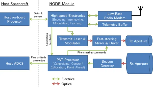
The functional block diagram of NODE is pictured in Figure 2-2. The host space-craft interfaces with the NODE processor to share telemetry and control the NODE module. While tracking, NODE shares the fine attitude knowledge it receives from the beacon detector to its host so that the host can improve its body pointing. Based on the feedback received from the beacon detector, the PAT processor in NODE cen-troids the image and computes the boresight offset to control the fast-steering mirror (FSM). The FSM corrects the transmit beam. A calibration loop provides feedback from the ground to correct Tx/Rx path misalignment, which is described in detail in Section 2.3.4.
Figure 2-2: Functional block diagram of NODE.
2.1.2
Summary of Key Parameters
A radiometric analysis was conducted to specify the downlink beamwidth, which is the key parameter of the system [50]. Several assumptions and design choices led to the final beamwidth of 2.1 mrad, which are briefly discussed here. A downlink wavelength of 1550 nm was selected due to the wide availability of COTS compo-nents from the telecommunications industry. Similarly, the wavelength for the uplink beacon was selected to be 850 nm, which enables the use of CMOS or CCD sensors. These detectors are low power and do not require cooling as is the case with InGaAs detectors.
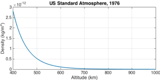
The link range was set at 1000 km, since CubeSats are typically launched into 400 to 700 km orbits, shown in Figure 2-3. The target orbit for which the system is designed is just above 400 km, which is the orbit of the International Space Station (ISS). The company NanoRacks added a CubeSat deployer to the ISS in early 2014, and since then it has deployed 61 CubeSats [51]. This has led to the ISS-orbit becom-ing one of the most common orbits for CubeSats. Lower altitudes place greater stress
on the PAT subsystem since the satellite must slew rapidly (up to around 1 degree per second) to track the ground station and the aerodynamic drag environment produces much greater disturbances.
Figure 2-3: Histogram of CubeSat orbital altitudes from 2010-2014.
Modest performance assumptions were made for the ground station. It is assumed to be 30 cm in diameter with a receiver sensitivity of 1000 photons/bit. Taking into account atmospheric and path losses, the beamwidth was adjusted to achieve a performance of 10 Mbps, resulting in a FWHM beamwidth of 2.1 mrad. The key system parameters for NODE are summarized in Table 2.1.
2.2
Pointing, Acquisition, & Tracking Architecture
The key decisions in the design of the PAT system are described in this section. As compared to The Aerospace Corporation’s OCSD mission, the architecture of NODE is quite different, particularly in the addition of a fine pointing stage. NODE is also unique in having a bistatic architecture as compared to most lasercom missions which have a monostatic design. The motivation and implications of these design decisions are discussed, followed by layout and hardware selection.
Table 2.1: Summary of key parameters of NODE. Downlink Parameters
Link rate 10 Mbps (baseline, uncoded) 100 Mbps (stretch, uncoded) Wavelength 1550 nm
Bit error rate 1 × 10⁻⁴ (uncoded) Link range ≤ 1000 km
Beamwidth 2.1 mrad (FWHM) Space Segment Parameters Size 10 × 10 × 5 cm3
Mass 0.5 kg
Power consumption 10 W (max. during Tx) Fine pointing range ± 1.0∘
Fine pointing accuracy ±1.05 mrad (3-𝜎) Beacon detector type CMOS focal plane array Beacon detector FOV 6.6∘
Receive aperture 2.54 cm
Ground Segment Parameters Beacon wavelength 850 nm
Beacon power 10 W
Acquisition detector type InGaAs focal plane array Comm. receiver type APD/TIA
Receive aperture 30 cm
2.2.1
Concept of Operations
The pointing, acquisition, and tracking approach for NODE follows the same flow that was introduced in Section 1.2.1. The concept of operations for PAT on NODE is shown in Figure 2-4 with three major steps. In addition to these steps, an optional Tx/Rx path calibration procedure can be performed during tracking.
The host CubeSat points towards the expected location of the ground station and looks for an uplink beacon. The beacon detector on NODE is large enough that the host should not need to scan for the beacon. Once the beacon is seen, the detector
Figure 2-4: Concept of operations for pointing, acquisition, and tracking on NODE.
centroid provides a direct measurement of the pointing error in the body frame. This measurement is fed back to the host satellite to improve its pointing.
At this point, the satellite undergoes a transition from being primarily sensing-limited to primarily actuation-sensing-limited as it attempts to center the beacon on the detector. As discussed in Section 1.3, attitude determination is a major limitation in current CubeSat pointing performance. Once the beacon is acquired, attitude knowledge is no longer the major source of pointing error. This allows the host satellite to improve pointing performance to overlap with the fine stage.
The fast steering mirror provides a final correction to the downlink to achieve fine pointing. The host satellite and fine stage continue to track the beacon for the duration of the pass. As the final step, a calibration procedure can be executed to correct Tx/Rx path alignment if necessary.
2.2.2
Single-Stage vs. Two-Stage Design
The decision to pursue a two-stage PAT design was the result of the requirements flowdown shown in Section 2.1.1. To be compatible with a typical CubeSat, NODE was constrained to use no more than 10 W of power during communications. With less power, a tighter beamwidth is required, and 2.1 mrad was the largest beamwidth
that could support a 10 Mbps downlink.
For a FWHM beamwidth of 2.1 mrad, constraining the pointing error to be within ±1.05 mrad (3-𝜎) will limit pointing losses to 3 dB, given that the transmitted laser signal has a Gaussian profile. Figure 2-5 shows pointing loss as a function of pointing error, with the pointing requirement highlighted in gray. For diffraction-limited laser-com systems the pointing accuracy can be as tight as 1/10th of the diffraction-limited beamwidth, and the optimal ratio of pointing accuracy to beamwidth is around 4 for these systems [52]. However, for systems that are not diffraction limited, the require-ment can be relaxed. The pointing requirerequire-ment for NODE is set at the half-power point, beyond which the losses grow rapidly.
Figure 2-5: Pointing loss as a function of pointing error (requirement shown in gray).
With a pointing requirement of ±1.05 mrad (3-𝜎), a single-stage design is beyond existing nanosatellite capabilities. The current pointing capabilities of CubeSats, as discussed in Section 1.3, are just at the cusp of achieving sub-degree RMS error (i.e. error less than 17 mrad on average). Given the constraint of 10 W maximum power consumption, it is not possible to close the link with just body pointing unless an extremely capable ADCS is pursued. A fine pointing stage must be introduced to
provide a 10 Mbps downlink for a CubeSat with standard pointing capabilities. While staged control is a common technique in lasercom systems, it is a novel concept for CubeSats. The only proposed two-stage pointing system on a CubeSat is the ExoplanetSat mission developed jointly at the MIT SSL and Draper Labora-tory [53]. ExoplanetSat is a 3-U CubeSat designed to detect exoplanets via the transit method. Due to the high photometric precision required of the imager, very precise pointing within 20 arcseconds (97 𝜇rad) is necessary. Fine stage control on Exoplan-etSat consists of a piezoelectric linear stage that translates the imager in two axes, and the imager is used for star tracking to provide fine attitude knowledge. While the two-stage control approach has not been demonstrated on orbit, simulation results predict a 3-𝜎 pointing precision of 2.3 arcseconds (11 𝜇rad).
NODE takes a different approach to two-stage control. ExoplanetSat is concerned with maintaining star position very precisely on the imager, which it achieves by directly actuating the imager on a stage. For lasercom, the primary concern is the outgoing signal. A design similar to ExoplanetSat is possible if the beacon receiver is collocated with the transmitter on the piezoelectric stage. Fine steering could then be conducted with the two-axis stage, but this has several drawbacks. The piezoelectric stage utilized in ExoplanetSat is about 1/4-U in size, which is too large to meet the overall 1/2-U requirement of NODE. Additionally, the range of the stage is 100 𝜇m, which in angular space is well under a degree for reasonable focal lengths of the beacon receiver. This is not sufficient to overlap with standard CubeSat body pointing.
NODE uses a static beacon receiver for fine attitude knowledge and a tip/tilt FSM to point the downlink. To motivate the two-stage control approach, it is useful to compare key parameters of NODE to key parameters of OCSD (introduced in Section 1.4.1) which takes a single-stage body pointing approach. Table 2.2 shows a side-by-side comparison of NODE and OCSD.
OCSD and NODE are comparable in size, link range, and ground station size. To close the link budget, NODE introduces a fine-pointing stage and reduces the beamwidth. OCSD approaches this problem by increasing optical output power and consequently the consumed power. To provide the required power, OCSD uses two
Table 2.2: Comparison of key parameters for OCSD and NODE.
OCSD NODE
Link range 900 km 1000 km
Size 10 × 10 × 15 cm3 10 × 10 × 5 cm3 (NODE module) 10 × 10 × 34 cm3 (target host satellite)
Data rate 5-50 Mbps 10-100 Mbps Pointing requirement ±0.1∘ (1-𝜎) ±0.06∘ (3-𝜎)
±1.7 mrad (1-𝜎) ±1.05 mrad (3-𝜎) FWHM Beamwidth 0.35∘ 0.12∘
6.1 mrad 2.1 mrad Peak power consumption 50 W 10 W Ground station aperture 30 cm 30 cm
18650 lithium ion batteries [7].
Referring to the basic link equation (see Equation 1.1), increasing transmitted power is linearly proportional to received power. Improving pointing accuracy al-lows a reduction in beamwidth, which increases the gain of the transmitted signal quadratically. The gain is directly related to directivity, which is given by:
𝐷 = 4𝜋 Ω𝐴
(2.1)
where Ω𝐴 is the solid angle subtended by the beam. This is simply the ratio of the
surface area of a sphere to the solid angle of the beam. The solid angle of a cone with apex 𝜃 is:
Ω𝐴= 2𝜋(1 − cos 𝜃) (2.2)
With a small angle approximation, this becomes:
This gives directivity as a function of beamwidth 𝜃:
𝐷 ≈ 4
𝜃2 (2.4)
Improving the pointing of the lasercom terminal allows a reduction in beamwidth with a quadratic gain, whereas increasing power is only linear. Based on this logic, NODE addresses the challenge of pointing rather than increasing power directly. This allows similar performance capability within typical power usage for a CubeSat.
2.2.3
Monostatic vs. Bistatic Design
The choice between a monostatic and bistatic architecture was an important decision in the early design process. A monostatic design has a shared Tx/Rx path with a single aperture, whereas a bistatic design has split Tx and Rx paths with independent apertures as shown in Figure 2-6. While some systems may have a separate aperture to acquire the uplink beacon, the uplink signal path during tracking is almost always shared with the downlink path in a monostatic architecture (refer to Figure 1-5).
Figure 2-6: Block diagram of monostatic and bistatic architectures.
feed-back for the fine stage. The tip/tilt of the FSM acts on both the Tx and Rx signals, ensuring that a well-designed controller can eliminate steady state pointing error. With the bistatic design, closed loop feedback is lost. The FSM acts only on the downlink, so if the Tx and Rx paths are misaligned it cannot be detected. This could occur due to mechanical misalignment during launch, thermal variations on orbit, or a change in the response characteristics of the FSM.
The justification for a monostatic design was based primarily on size constraints. A link budget was conducted on the uplink beacon and a 25 mm diameter on the Rx aperture is necessary to collect enough signal to identify the beacon [50]. The FSM is constrained to a size less than 5 mm due to limited COTS actuators that fit within NODE. These parameters were not flexible and made a monostatic design extremely challenging, as described below.
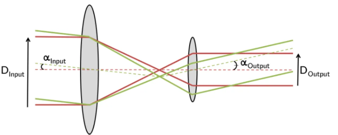
The incoming signal from the receive aperture may either be collimated or left uncollimated and focused directly onto the beacon detector. Each of these cases presents significant challenges. If the beam is collimated, it must be resized by a factor of 1/5 to fit on the FSM. However, by reducing the size of the collimated beam, the off-axis angle is magnified by the resize factor. This concept is shown in Figure 2-7 and described by:
𝛼𝑂𝑢𝑡𝑝𝑢𝑡
𝛼𝐼𝑛𝑝𝑢𝑡
= 𝐷𝐼𝑛𝑝𝑢𝑡 𝐷𝑂𝑢𝑡𝑝𝑢𝑡
(2.5) If the incoming angle is 1∘ off-axis due to body pointing error, the resized beam will have an error of 5∘ that the FSM must correct. This exceeds the capabilities of COTS actuators to meet the range and resolution required for fine steering, and also presents the issue of beam walk-off. Coarse stage body pointing errors are on the order of a degree based on CubeSat body pointing capabilities, so the incoming signal may be off-axis as much as several degrees which is then magnified by beam resizing.
If the beam is not collimated, then the aperture size is limited by the FSM, and the link cannot be closed. More power could be put into the beacon, but the design begins
Figure 2-7: Angular magnification with beam reduction. Off-axis incoming light (green) as compared to on-axis light (red) for reference.
to encroach upon laser safety regulations [19]. Based on these concerns, a bistatic design was pursued, and a semi-closed loop calibration method was developed to compensate for Tx/Rx path misalignment.
2.2.4
Hybrid Laser & Radio Calibration Method
Since NODE has a bistatic configuration, the FSM tracks the ground station in an open loop manner. Pointing bias may occur due to a variety of factors, such as mechanical or thermally-induced misalignment of optical components or a shift in response characteristics of the FSM. A means of calibrating out this bias is needed to ensure that fine steering requirements can be met.
While there is no closed loop feedback on NODE, power measurements from the ground can be sent back to NODE through the low-rate RF link. This concept is shown in Figure 2-8. The laser beam profile is a two-dimensional Gaussian. While the FSM tracks the beacon, the tip/tilt angles can be modified slightly. The ground station will take a time-averaged power measurement, which will be relayed to the RF ground station and transmitted back to the satellite. By repeating this pattern, NODE can calibrate out the mispointing until the ground is receiving at the peak of the signal.
This approach presents several challenges, which are addressed in detail in Section 3.2. The primary challenge is the atmospheric channel. This will cause time-varying
Figure 2-8: Hybrid laser downlink and radio uplink calibration concept.
intensity on the ground that will inject noise into the power measurements. An additional challenge is the time-shifting power curve over the duration of the pass. As the orbital trajectory approaches the ground station, received power will increase as the link range decreases. Likewise, as the satellite recedes from the ground station received power will decrease. This time-shifting power makes relative comparisons between measurements a challenge. Finally, the calibration approach may be applied during communications (i.e. while transmitting data) so the pointing adjustments must be small enough to avoid compromising the link.
2.3
Derivation of Requirements
From the high level system requirement of providing a >10 Mbps downlink for a typical SWaP-constrained CubeSat, requirements are levied on PAT system
perfor-mance. The key challenge for the PAT subsystem is to bridge the gap between current CubeSat pointing capabilities and the required pointing for high bandwidth lasercom.
2.3.1
Host Spacecraft Performance
Three requirements are placed on the host spacecraft’s ADCS to be compatible with NODE. CubeSat pointing capabilities are just beginning to achieve sub-degree error, as described in Section 1.3. With this figure in mind, NODE is designed to support CubeSats with an initial pointing accuracy of ± 3∘(3-𝜎). The beacon receiver requires this accuracy to see the beacon within its FOV.
The second constraint comes after beacon acquisition. The host satellite will correct its pointing in response to the beacon receiver feedback, with the aim of centering the beacon on the camera. At this point, the satellite is receiving very fine attitude feedback and with this it must be able to point within ±1∘(3-𝜎). This allows an overlap with the fine steering stage range so that fine corrections can be applied.
The final requirement is that the CubeSat must support slew rates of up to 1∘/sec to enable ground tracking from a 400 km orbit. These requirements are summarized in Table 2.3.
Table 2.3: Host spacecraft performance requirements for compatibility with NODE. Parameter Performance Req. Reason
Pre-acq. pointing ±3∘ (3-𝜎) Beacon must be within camera FOV.
(no beacon) 52 mrad (3-𝜎)
Post-acq. pointing ±1∘ (3-𝜎) Must overlap with fine stage range.
(beacon feedback) 17 mrad (3-𝜎)
Slew rate 1∘/sec Max. slew to track ground station at 400 km.
2.3.2
Fine Steering Requirements
The fine steering must bridge the gap between coarse stage body pointing and the accuracy required to close the link. There are two major requirements placed on the
fine stage, which are the range and accuracy. The fine stage range must be larger than ±1∘ to overlap with the coarse stage. The optical beam deflection will be up to twice as much as the range depending on the optical configuration, so this ensures that the fine steering mechanism will not be operating near saturation.
The second requirement of the fine stage is that it provide steering accuracy to ±1.05 mrad (3-𝜎), which limits pointing loss to 3 dB or less. This requirement is intentionally conservative, and if pointing performance significantly exceeds the requirement higher data rates can be achieved. The requirements for fine steering are summarized in Table 2.4.
Table 2.4: NODE fine steering requirements. Parameter Performance Req. Reason
Range >1∘ Must overlap with coarse stage post-acquisition pointing.
Pointing accuracy ±0.06∘ (3-𝜎) Max. pointing loss of 3 dB.
1.05 mrad (3-𝜎)
2.3.3
Beacon Detector Requirements
The beacon from the ground provides fine attitude knowledge to NODE and its host CubeSat. Two requirements are placed on the detector, shown in Table 2.5. The FOV of the detector must be large enough to acquire the beacon with the expected host body pointing error. This error is limited to ±3∘ based on CubeSat pointing capabilities, so the detector FOV must be at least 6∘. The attitude knowledge must be sufficient to support the pointing requirement of ±1.05 mrad, so a requirement is placed on the beacon detector to achieve a centroid measurement accurate to better than ±0.1 mrad, a factor of ten better than the required pointing.
![Figure 1-2: Absorption of the electromagnetic spectrum in the Earth’s atmosphere [2].](https://thumb-eu.123doks.com/thumbv2/123doknet/14732735.573407/24.918.236.689.332.728/figure-absorption-electromagnetic-spectrum-earth-s-atmosphere.webp)
![Figure 1-5: Generic block diagram for PAT subsystem [3].](https://thumb-eu.123doks.com/thumbv2/123doknet/14732735.573407/29.918.232.687.106.426/figure-generic-block-diagram-for-pat-subsystem.webp)
![Figure 1-8: Reaction wheels developed by Sinclair Interplanetary for CanX-2 [6].](https://thumb-eu.123doks.com/thumbv2/123doknet/14732735.573407/34.918.233.686.665.900/figure-reaction-wheels-developed-sinclair-interplanetary-canx.webp)