Publisher’s version / Version de l'éditeur:
Vous avez des questions? Nous pouvons vous aider. Pour communiquer directement avec un auteur, consultez la Questions? Contact the NRC Publications Archive team at
PublicationsArchive-ArchivesPublications@nrc-cnrc.gc.ca. If you wish to email the authors directly, please see the first page of the publication for their contact information.
https://publications-cnrc.canada.ca/fra/droits
L’accès à ce site Web et l’utilisation de son contenu sont assujettis aux conditions présentées dans le site LISEZ CES CONDITIONS ATTENTIVEMENT AVANT D’UTILISER CE SITE WEB.
Student Report (National Research Council of Canada. Institute for Ocean Technology); no. SR-2005-30, 2005
READ THESE TERMS AND CONDITIONS CAREFULLY BEFORE USING THIS WEBSITE. https://nrc-publications.canada.ca/eng/copyright
NRC Publications Archive Record / Notice des Archives des publications du CNRC :
https://nrc-publications.canada.ca/eng/view/object/?id=a0eec834-7da4-4369-b14a-3f08c811c147 https://publications-cnrc.canada.ca/fra/voir/objet/?id=a0eec834-7da4-4369-b14a-3f08c811c147
Archives des publications du CNRC
For the publisher’s version, please access the DOI link below./ Pour consulter la version de l’éditeur, utilisez le lien DOI ci-dessous.
https://doi.org/10.4224/8895094
Access and use of this website and the material on it are subject to the Terms and Conditions set forth at GAVIA as a pipeline inspection vehicle
REPORT NUMBER
SR-2005-30
NRC REPORT NUMBER DATE
December 2005
REPORT SECURITY CLASSIFICATION
Unclassified
DISTRIBUTION
Unlimited
TITLE
GAVIA AS A PIPELINE INSPECTION VEHICLE
AUTHOR(S)
G. Hewitt
CORPORATE AUTHOR(S)/PERFORMING AGENCY(S)
Institute for Ocean Technology, National Research Council, St. John’s, NL
PUBLICATION
SPONSORING AGENCY(S)
IOT PROJECT NUMBER
42_2091_10
NRC FILE NUMBER KEY WORDS
Pipeline Inspection, GAVIA
PAGES 23, App. A-B FIGS. 17 TABLES 1 SUMMARY
The GAVIA autonomous underwater vehicle (AUV) was purchased through a joint venture of the Institute for Ocean Technology (IOT) and the Institute for Research in Construction (IRC). The vehicle will provide a platform from which freshwater piping systems could be inspected from the inside without removing them from service. In order to stay centralized inside these pipes the vehicle needed to be fitted with centralization legs.
Also described in this report is a mechanism whereby laser line scan can be used to inspect these pipes for cracks, or obstructions. A line laser is directed at the wall of the pipe and a camera captures the image of the laser intersecting the wall. A series of these images can be assembled to indicate the condition inside the pipe.
In order to test both the legs and the line scan device, a linear-travel test apparatus is currently being set up in the AUV Lab. This apparatus consists of a 2.5 metre linear slide, driven by a servomotor. This will allow us to place the components into a test section of pipe and move them thought the pipe at a constant speed, mimicking the movement of the GAVIA vehicle inside a pipe.
ADDRESS National Research Council
Institute for Ocean Technology Arctic Avenue, P. O. Box 12093 St. John's, NL A1B 3T5
Institute for Ocean Institut des technologies
Technology océaniques
GAVIA AS A PIPELINE INSPECTION VEHICLE
SR-2005-30
Gerald Hewitt
Summary
The GAVIA autonomous underwater vehicle (AUV) was purchased through a joint venture of the Institute for Ocean Technology (IOT) and the Institute for Research in Construction (IRC). The vehicle will provide a platform from which freshwater piping systems could be inspected from the inside without removing them from service.
In order to facilitate this inspection, the vehicle has to be fitted with centralization legs that keep the vehicle centered in the pipe. The first generation of these legs have been developed and built. They are constructed of PVC, with enough flex to exert a force normal to the walls of the pipe. The force exert by the legs was modeled mathematically, and it was determined that each of the six legs exerts approximately 10 N of force when placed inside a 36 inch diameter pipe. The second generation of these legs is currently in a design phase. These legs will be retractable and articulated.
Also described in this report is a mechanism whereby a laser line-scan device can be used internally to inspect these pipes for cracks, or obstructions. A line laser is directed at the wall of the pipe and a camera captures the image of the laser intersecting the wall. A series of these images can be assembled to indicate the condition of the inside wall of the pipe.
In order to test both the legs and the line-scan device, a linear-travel test
apparatus is currently being set up in the AUV Lab. This apparatus consists of a 2.5 metre linear slide, driven by a servomotor. This will allow us to place the components into a test section of pipe and move them thought the pipe at a constant speed, mimicking the movement of the GAVIA vehicle inside a pipe.
Table of Contents
Summary ...1
Table of Contents ...2
List of Figures...3
1.0 Background ...4
2.0 GAVIA as a Pipeline Inspection Vehicle ...5
3.0 Centralization Legs for GAVIA...6
3.1 Leg Design...6
3.2 Modeling the Legs as Springs...7
3.3 Theoretical Stiffness (K) Values...9
3.4 Modeling with MATLABX SimulinkX and V-RealmX...11
3.5 Articulated Legs ...14
4.0 Laser/Camera Combination for Pipeline Inspection Vehicle...15
5.0 Linear Motion Slide...18
6.0 GAVIA Electronics Extraction Tool ...20
7.0 Conclusions...21
8.0 References ...22
List of Figures
Fig 1.1 GAVIA Autonomous Underwater Vehicle... 4
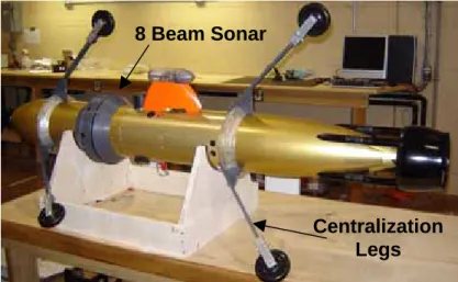
Fig 2.1 GAVIA with Legs and Sonar attached... 5
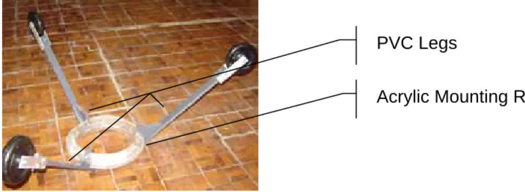
Fig 3.1 Centralization Legs and Acrylic Ring ... 6
Fig 3.2 Centralization Leg Attachment ... 7
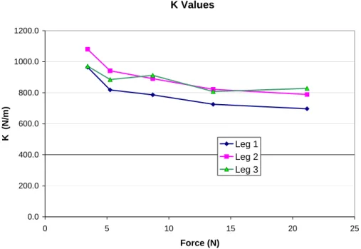
Fig 3.3 Values of Spring Constant for Leg Modeling... 8
Fig 3.4 Beam Deflection Diagram ... 9
Fig 3.5 Moment of Inertia Diagram... 9
Fig 3.6 Leg Test Arrangement ... 10
Fig 3.7 GAVIA V-Realm Model ... 12
Fig 3.8 Simulink Block Diagram for Leg Response ... 13
Fig 3.9 Articulated Leg in Extended and Retracted Positions ... 14
Fig 4.1 Line Scan Profiling Concept... 16
Fig 4.2 Optical Triangulation Using Line Scan Imaging ... 16
Fig 4.3 Laser Line Scan Test Apparatus... 17
Fig 4.4 Grayscale Image as seen using Line Scan Apparatus... 17
Fig 5.1. Belt Driven Linear Motion Slide... 18
1.0 Background
The GAVIA autonomous underwater vehicle is designed and built by Hafmynd Ltd. of Iceland. The vehicle is designed for fully autonomous operation in the open ocean. Its hull is machine-ground corrosion resistant aluminum alloy which makes the vehicle suitable for depths up to 200 metres. The vessel is propeller driven and is powered by a 1.5 kilowatt-hour lithium battery.
It is also equipped with a communications system that allows the operator to communicate with it before, during and after missions. The communications options include: high-speed wireless LAN and global Iridium satellite link. During the mission the operator can also communicate with the vehicle using an
acoustic underwater telemetry system. The GAVIA vehicle is also completely modular, as shown in Fig 1.1, with a communications bus connecting each
module. This means that custom modules can be built and added to the vehicle. This was one of the reasons why GAVIA was selected for this project.
2.0 GAVIA as a Pipeline Inspection Vehicle
The GAVIA vehicle currently housed at the Institute for Ocean Technology was purchased through a joint venture between the NRC Institute for Ocean
Technology (IOT) and the NRC Institute for Research in Construction (IRC) in Ottawa. The purpose of the vehicle in this application is to inspect freshwater piping systems. Throughout North America, aging infrastructure in many major cities has created a need for internal inspection of these concrete pipes, while in service. The goal of this work is to develop a vehicle, based on the GAVIA platform, to carry the required sensors through these pipes, identify areas that need attention and do so without interrupting or contaminating the fresh water supply of the city.
The first step upon the GAVIA arrival was to establish communications with, and control over the vehicle. These initial tests were conducted in the Offshore
Engineering Basin (OEB) at IOT. The next set of tests demonstrated the concept by piloting the vehicle through 36” pipes to show that it could be used for the freshwater pipe inspection. This was also conducted in the OEB with a 50’ section of pipe. For this test the vehicle was also equipped with a radial 8-beam sonar that was used to profile the inside of the pipe.
Centralization Legs 8 Beam Sonar
3.0 Centralization Legs for GAVIA
3.1 Leg Design
To keep the vehicle centralized inside the pipe six stabilization legs were
required. The mounting ring used to secure the legs was made from four sheets of acrylic material glued together and machined to the dimensions required. The initial design of the legs was to use a graphite rod with a wheel and swivel caster at the end. Soon after prototypes were constructed, it became obvious that this design would not work. The graphite rods were too flexible to keep the vehicle from hitting the wall, and the swivel-caster was too heavy for this application.
The second leg design removed the swivel casters and used only the wheel itself. The graphite rods were replaced with 3/8” x 1” PVC rods. PVC was selected because of its light weight, flexibility and workability. It was also readily available at relatively low cost.
Acrylic Mounting Ring PVC Legs
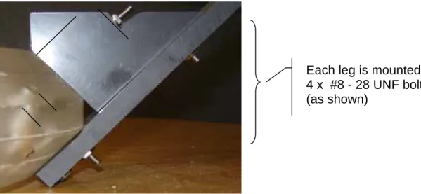
Each leg is mounted using 4 x #8 - 28 UNF bolts. (as shown)
Fig 3.2 Centralization Leg attachment
The legs were designed so that the wheels would run inside a pipe of ID 37”. This meant that each leg flexed ½” when the vehicle entered a 36” ID pipe. This geometry seemed to work quite well. During testing, when the vehicle was inside the 36” test pipe it was constrained to travel along the longitudinal centerline of the pipe.
3.2 Modeling the Legs as Springs
In order to determine the force that was exerted by the legs on the wall of the pipe we experimentally determined a spring constant, k, to mathematically describe the performance of the PVC legs. We determined the spring constant, over the appropriate range of motion, to be approximately 800 N/m. With a neutrally buoyant vehicle in a completely filled pipe, this corresponds to an outward force of 10 N exerted by each leg on the wall of the pipe. This means that if the vehicle is 10 N (approximately 1 kg) heavy, the top wheel will still be in contact with the pipe wall.
In order to facilitate measuring the spring constant the mounting ring was clamped in a vise so that each of the legs, in turn was vertical. Next, five
different weights were hung from the wheel axle and the displacement measured from vertical. In this way the experiment closely approximated the scenario of the legs flexing as they enter a reduced diameter pipe. The points for each leg were plotted and k values calculated. The k values do vary slightly from leg to leg, likely due to differences in attachments and slight variations in effective length (i.e. the amount of PVC that is available for bending.
K Values 0.0 200.0 400.0 600.0 800.0 1000.0 1200.0 0 5 10 15 20 25 Force (N) K (N/m) Leg 1 Leg 2 Leg 3
3.3 Theoretical Stiffness (K) Values
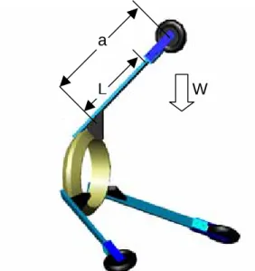
The theoretical k value was calculated using the standard equation for describing the flex of a beam under load:
EI a L Wa v 6 ) 3 ( 2 max − = a L Where: vmax
Vmax = Max deflection
L = Length of Beam
W a = Location of applied force
W = Applied force at position ‘a’
E = Young’s Modulus for PVC Fig 3.4 Beam Deflection Diagram
I = Moment of Inertia
The moment of inertia, I, is calculated from:
h 4 9 3 3 10 815 . 1 0095 . 0 0254 . 0 12 1 12 1 m bh I = = ⋅ ⋅ = × − b
Fig 3.5 Moment of Inertia Diagram
In our case the load was applied at the point of contact between the wheel and the wall, which was collinear with the wheel’s axle where the load was applied for this test. To simplify the calculation, we assumed that there was no flex in the aluminum mounting brackets, or in the portion of the leg that was supported by the bracing. This was a reasonable assumption since the bracing is rigid and the
aluminum-mounting bracket is oriented perpendicular to the plane of flex (I=8.7x10⁻⁹, 5 times larger then the PVC).
Based on this assumption, and with the setup as shown below, the length (L) available for flexure is actually shorter then the distance to the applied load (a)
W a
L
Fig 3.6 Leg Test Arrangement
Rearranging the basic flexure equation and with L=0.229 m and a=0.330 m, we get: m N a L a EI v W k 877 / ) 330 . 0 229 . 0 3 ( ) 330 . 0 ( ) 10 815 . 1 )( 10 31 . 3 ( 6 ) 3 ( 6 2 9 9 2 max = − ⋅ × × = − = = −
This shows that the error between the measured value and theoretical value is:
% 6 . 9 % 100 800 800 877 %error= − × =
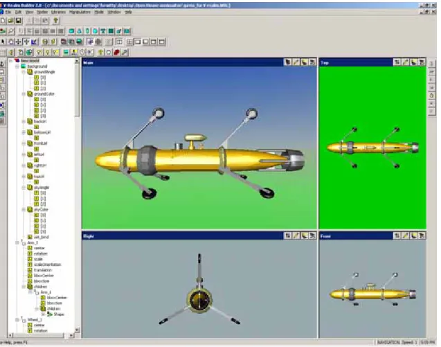
3.4 Modeling with MATLABX SimulinkX and V-RealmX
Once the spring constant was established a SimulinkX model was developed to describe the response of the legs to varying inputs. This block diagram is shown in figure 3.7. It uses the calculated spring constant K and an estimated damping factor to describe the motion of the legs. The output of this model was used to drive a Virtual Reality model of the GAVIA with its legs attached. This virtual reality model was developed using V-Realm and imported AutoCADX drawings. It started with the AutoCAD drawing of the GAVIA as supplied by the
manufacturer. Within AutoCAD the legs and support rings were then drawn and added to the vehicle. This drawing was then imported into V-Realm as a 3D Studio file (*.3ds). From here each component (leg, wheel, body) had its center of rotation and translation defined. These are defined using four components (X,Y,Z, coordinate of the center, and magnitude of translation or rotation). The file was then saved as a .wrl file. The Matlab VR toolbox has an option, VR Sink, which allows Simulink to feed calculated variables into the .wrl file. These
variables are first combined using the Mux block to form a vector of the required size and then fed into the VR sink as a vector. The four components of the vector define the rotation axis and magnitude.
Fig 3.8 Simulink Block Diagram for Leg Response
The first image shows the basic Simulink diagram and the modeled response of the legs. The diagram at the left is the
subsystem used to assign values to the vectors required to control the VMRL output file. The X,Y,Z values for each output define the axis of rotation for each leg in the virtual 3D space. The gain that is applied to each signal allows the user to define the direction of rotation for each leg.
3.5 Articulated Legs
The next generation of legs for the GAVIA vehicle will be retractable and articulated. This is required firstly to allow the vehicle to be inserted into and removed from the pipe through small openings. Service openings in freshwater piping systems are not always the same diameter as the main pipe body so the vehicle should be as compact as possible if these access-ways are to be used. The retractable legs will also allow the vehicle to move through pipes of different diameters, and still apply force on the walls of the pipe.
These legs will consist of a four-bar linkage as shown below. The design criteria for this linkage were:
1) Permit the leg to be collapsed in such a way as the linkages only occupy 2” of height and the wheel protrudes from the linkages to contact the walls before the body of the vehicle
2) When fully extended the wheel should be 18” from the centerline of the pipe and the arm on which the wheel is fixed should be slightly inclined.
As is the case with the current prototype, the new design will also consist of two sets of three legs. Some of these legs will also contain encoders for measuring distance traveled and electromechanical brakes to slow down or stop the vehicle, when traveling inside the pipe.
4.0 Laser/Camera Combination for Pipeline Inspection Vehicle
The idea behind this apparatus is to shoot a line laser at the inside wall of the freshwater pipe as the vehicle moves through the pipe and capture the image cast on the wall using a camera. In this manner, discontinuities or changes in texture of the pipe wall can be identified.
Figure 4.1, below, shows a 3D view of the profiling concept. You can see the fan shaped laser beam illuminate the pipe wall. Both an obstacle and a cavity are present. The image captured by the camera represents the intersection line between the laser beam and the pipe wall. This image can be examined and anomalies located.
If we store the position where we found the maximum intensity, and store the gray level (i.e. intensity) at the position of the maximum value, we will get an image line along the laser line. By moving the laser/camera inside the pipe, and making a new exposure each millimeter of travel, we can build an image of the inside wall of the pipe by putting these lines together.
Fig 4.1 Line Scan Profiling Concept
Once the location of anomalies is determined we can use the camera to also investigate the depth of a cavity or extent of a protrusion. The image below shows how optical triangulation works. As long as the angles and distance between the laser and camera are held constant, the shift in the received image is dependant on the distance from the laser to the surface of the pipe. This shift indicates the extent of cavities or protrusions.
A test apparatus was constructed to demonstrate this principle. This apparatus consisted of a Pixelink PL-A741 camera mounted on an angle-adjustable base and a Class II line laser on a sliding mount, as shown in Fig 4.3.
Laser
Camera
Fig 4.3 Laser Line Scan Test Apparatus
A section of the 36” plastic pipe was mounted on the test bench and the camera and laser were inserted. Both ends of the pipe were closed to eliminate
interference. A grayscale pattern was attached to the wall of the pipe and an image captured. Figure 4.4 below shows the grayscale image outside the pipe (top), and as seen by the Pixelink camera (bottom). As can be seen in the grayscale image, distinctions between color changes are subtle but
distinguishable using this system.
Greyscale pattern as it was fixed to the inside wall of the pipe
Image captured by the camera
5.0 Linear Motion Slide
In order to accurately control the location and movement of the apparatus within the test section of pipe a linear motion slide was purchased. This system will also serve as a testing ground for the articulated legs described above.
Fig 5.1. Belt Driven Linear Motion Slide
The criteria for this slide were:
Speed: 1.5 m/s Travel: 2.0 m Load: 10 kg Resolution: 0.2 mm Encoder: Yes Waterproof: If possible
Because of the speed required to mimic the motion of the GAVIA vehicle within a pipe, a lead/ball screw slide was not practical. However, belt driven slides were available to meet this criterion at a reasonable price. The next decision was whether to use a stepper or servo-motor. A stepper motor and driver were significantly less expensive, but a servo-motor was selected because of its versatility.
Several suppliers were approached for quotations . It became apparent that finding a system suitable for use underwater would be difficult and extremely expensive. We then set out to find the apparatus that provided the best
performance, at the best price, that was not waterproof, but was constructed mainly from stainless steel and aluminum.
The list of possible suppliers was assembled. This included: Techno-Isel, Bisho-WiseCarver, Numatics, Lintech, Parker-Hannifin and Danaher. Each of these companies provided quotes and the list was quickly narrowed down to Techno-Isel, Danaher, and Numatics.
Company Contact Phone Product Quote
THK Kaz Kuwabara -
Jason Lee
(905) 820-7800 GL15B+2000L-NR $ 3,476.00
BishopWisecarver Michael Firman (888) 580-8272 LoPro 1 - W-B-A-CR $ 1,913.00 LoPro 2S - W-B-A-CR $ 1,975.00 Techno-Isel - (Drive
Systems Group)
George Rabuzin (905) 405-0310 Ext.33 ZF3 $ 2,655.00
Numatics Paul Akerman (506) 658-8004 BDU 55 $ 2,590.00
BDU 75 $ 3,480.00
Danaher - Alberta Industrial Controls
Terry Magnus (780) 436-4848 R2A or R3 series
Lintech - Electromate Tom Shay (877) 737-8698 55310072-D1-M04-C293-L04-E00-B00 $ 6,765.00 Parker Hannifin - RG Shelly Michael Michael (800) 245-6903 (416) 447 6471 HPLA 080 $ 5,000.00
Table 5.1 Summary of Belt Driven Slide Information
Based mainly on price, Techno-Isel was selected to be the supplier. Details of each slide are presented in Appendix A.
6.0 GAVIA Electronics Extraction Tool
It had been noticed that the electronics modules of the GAVIA were constructed in such a manner as to leave very little clearance when removing them from the vehicle. In particular the nose and tail sections are very difficult to remove. Also, these sections are sealed to the body of the vehicle using an O-ring. To remove the electronics the O-ring seal has to be broken. This requires a significant force and it is hard to control the motion once it has started. On one occasion, removal of the tail section resulted in damage to several wires and a capacitor.
The extraction tool was designed to allow the sections to be removed from the vehicle in a more controlled fashion. The tool is made from two pieces of 1/8” x 1” aluminum. One piece mounts on the electronics module and the other on the GAVIA body. These pieces are connected using a nut and bolt. With both pieces in place, tightening the nut on the bolt draws the two pieces closer together and causes the electronics module to slide out in a controlled fashion.
7.0 Conclusions
The combination of versatility and size of the GAVIA vehicle make it an excellent foundation for research pertaining to the internal inspection of freshwater piping systems. Although modifications will be required, the base design has been established.
The way forward for this research lies in the design and construction of
articulated legs, and a vehicle module to accommodate them. Also required at this time is a mechanism for braking the vehicle and encoders to measure vehicle travel. The size of these components and forces exerted on them will clarify the requirements of the articulated legs.
8.0 References
Bishop Wisecarver Corporation, http://www.bwc.com/html/dls.html
Danaher Motion, http://www.thomsonindustries.com/default.htm
Engineer’s Edge, Beam Bending Equations
http://www.engineersedge.com/beam_calc_menu.shtml
GAVIA, Great Northern Diver, http://www.gavia.is/
Lintech Motion, http://www.lintechmotion.com/
Norsk Elektro Optikk, Specialists in Electro Optic Technology
http://www.neo.no/research/pipeline/
Numatics Linear Motion, http://www.numatics.com/
Parker Haniffin, http://www.parkermotion.com/
Techno-Isel Inc., http://www.techno-isel.com/tech_linearsystem.htm
THK Industries, http://www.tos-world.com/
V-Realm Builder, User Guide and Reference. Ligos Corporation, 6001 Chatham Drive, Savannah GA. http://www.cs.vu.nl/~eliens/documents/vrml/V-Realm/