HAL Id: hal-03187709
https://hal.inria.fr/hal-03187709
Submitted on 1 Apr 2021
HAL is a multi-disciplinary open access
archive for the deposit and dissemination of
sci-entific research documents, whether they are
pub-lished or not. The documents may come from
teaching and research institutions in France or
abroad, or from public or private research centers.
L’archive ouverte pluridisciplinaire HAL, est
destinée au dépôt et à la diffusion de documents
scientifiques de niveau recherche, publiés ou non,
émanant des établissements d’enseignement et de
recherche français ou étrangers, des laboratoires
publics ou privés.
Interactive Finite Element model of needle insertion and
laceration
Pedro Henrique Suruagy Perrusi, Paul Baksic, Hadrien Courtecuisse
To cite this version:
Pedro Henrique Suruagy Perrusi, Paul Baksic, Hadrien Courtecuisse. Interactive Finite Element model
of needle insertion and laceration. Eurographics 2021 - The 42nd Annual Conference of the European
Association for Computer Graphics, European Association for Computer Graphics, May 2021, Vienne
/ Virtual, Austria. �10.2312/egs.20211020�. �hal-03187709�
Interactive Finite Element model of needle insertion and laceration
P. H. S. Perrusi , P.Baksic , H. Courtecuisse
AVR/ICube, CNRS and Strasbourg University, Strasbourg France
Abstract
This paper introduces an interactive model of needle insertion, including the possibility to simulate lacerations of tissue around the needle. The method relies on complementary constraints to couple the Finite Element models of the needle and tissue. The cutting path is generated from mechanical criteria (i.e. cutting force) at arbitrary resolution, avoiding expensive remeshing of Finite Element meshes. Complex behavior can be simulated in real time such as friction along the shaft of the needle, puncture and cutting force resulting from interactions of the needle with the tissue. The method is illustrated both in an interactive simulation of a needle insertion/cutting and in a robotic needle insertion in liver tissue during the breathing motion.
CCS Concepts
•Computing methodologies → Physical Simulation; Real-Time Simulation;
1 Introduction
Needle-based approaches are more and more chosen as a viable op-tion for various medical applicaop-tions ranging from biopsies to sur-gical treatment (such as Radio Frequency Ablation of liver tumors). Yet, despite many benefits for patients it also increases the technical difficulty for practitioners, pushing the need for training solutions. Simulation has become a powerful tool in learning [AE10], espe-cially in the medical field where the practice of surgical procedures is essential to reduce the post-operative damages.
Among the difficulty to accurately place needles, additional con-straints lies in the fact that during the insertion needles may lacer-ate and damage surrounding tissues due to physiological motions of organs. Although the lacerations are limited when the needles are held by a practitioner (avoiding applying too much stress on the needle inside tissues), they are particularly observed when needles are held by a stiff robotic system [BJMB∗14], which is why some robotic devices were conceived to avoid this behavior [PBB∗09]. For percutaneous applications, the extents of the cuts are usually not sufficient to separate the tissue. Indeed, the compression of sur-rounding organs and the limited extension of the cut surface prevent the organs to mechanically separate in two parts in the abdominal cavity. The present method relies on this observation and introduces a new model for needle insertion and lacerations.
The proposed method relies on an intermediate plan defined inde-pendently from the needle and tissue mesh resolutions. The rupture and the extension of the cut plane are triggered by the amount of interaction forces between the needle and the tissue. The cut plane is used to simulate the additional degrees of freedom of the nee-dle inside the tissue, resulting in an interactive model of the cut, without any need for expensive remeshing operations.
2 Related Works
One of the first models for needle-deformable tissue interactions was proposed by DiMaio et al. [DS02]. Relying on a linear model, the method allows simulating stick-slip behaviors. Signifi-cant amount of work was also performed by Misra et al. [APM∗16], including experimental validations with robotic systems, in order to steer bevel-tip needles.
From a numerical point of view, large scale simulations involv-ing multiple organs and complex tissue interactions were proposed for training. Chentanez et al. [CAR∗09] presented a FE approach based on the beam’s theory to predict needle deflection. Yet, the method relies on expensive remeshing operations which raises ad-ditional difficulties to handle topological changes and deforma-tions as the needle penetrates the tissue, especially in an interactive environment. Duriez et al. [DGM∗09] introduced complementary constraints for the simulation of a needle insertion, avoiding this way remeshing operations. The method allows simulating complex phenomena such as tissue deformations, needle-tissue friction, and puncture force in real time. Fast GPU-based implementation has also been proposed [Pat12] for both nonlinear and linear elasticity. From a general point of view, the simulation of cut and topologi-cal modification has been widely studied. Methods can be classi-fied into three parts, namely the mesh-based methods, the meshless methods and hybrid methods [WM18].
Mesh-based methods simulate the deformations using FE and the cutting process with topological changes. Among those changes, the easiest one is the element deletion, which consists in deleting an element that crosses the cutting path [FDA05]. However, element deletion induces volume loss in the mesh and an approximative cutting surface. Other methods use element duplication for each
2 P. H. S. Perrusi & P. Baksic & H. Courtecuisse / Interactive Finite Element model of needle insertion and laceration
element crossing the cutting path [MBF04] but the volume of the mesh is still modified. To alleviate these issues, some methods pro-posed to re-mesh locally in order to fit the cutting path [PUC∗15]. However, although having a better cutting surface, it may create ill-shaped elements that lead to instabilities during the simulation. Meshless methods use particles and their interactions with neigh-bors to compute the deformation. In [CLLZ17], the cutting process is simulated when the forces increase above a threshold separating the two parts around the cutting plane. The main advantage is the reduced computation time but meshless methods lack of geometri-cal information that leads to a less efficient collision detection. Hybrid methods combine the advantages of both using a meshed surface and particles to compute the deformations. In [SLLW18], the authors reconstruct the surface mesh using an interactive trian-gulation algorithm during the cut. The cutting process can also be simulated using XFEM [KBT17], that will enrich the shape func-tions of the elements to introduce discontinuities.
Although lacerations represent an important concern from the med-ical point of view, very few methods have been proposed for the simulation of the cut by the needle. Bui et al. recently proposed to rely on nonconforming meshes [BTB19], but the method still raises stability and computational issues in an interactive context. The contribution of this paper is a hybrid method where the cut is modeled through complementary constraints. The method is an ex-tension of [DGM∗09] introduced for needle insertion. Based on mechanical criteria the method generates an intermediate plane, mapped into the volume mesh, describing the cutting path. Inter-actions between the needle and the cut surface are then handled by mechanical constraints, allowing this way to properly simulate the effects of the cut with a minimal amount of topological changes. 3 Constraint-based model of needle insertion
This section introduces the principles of the method inherited from [DGM∗09]. The needle is described as a set of serially linked beams composed of two nodes, each node having 6 DoFs (posi-tion and rota(posi-tion). The model of the needle is based on the Timo-shenko’s formulation, which relies on the beam’s theory. The vo-lumic model is meshed with linear tetrahedral elements and fol-lows the Hook’s law. In addition, to handle large displacements both models are combined with the co-rotational approach. After the discretization, the internal forces can be written as a nonlinear function F (q) where q are the nodal positions of the FE meshes. Note that the proposed solution is generic and could be applied to other nonlinear models.
An implicit integration of Newton’s second law is chosen in order to increase the stability during interactions. Lagrangian Multipliers are used to enforce constraints between the needle and the tissue. The non-linear problem formulation is explained in [AGM∗19]. The problem is solved with a single Newton-Raphson iteration (see [CAK∗14] for justification). The linearized problem can be represented by the following equation:
Wλ = δfree (1) where W is the schür complement of the system, λ are the con-straint forces and δfreethe free-motion interpenetration. Using com-plementary constraints both λ and δfreeare unknown. Indeed,
con-straints used in this work need to satisfy the Signorini’s law: 0 ≤ δ ⊥ λ ≥ 0 (2) The above equation means that either the objects are distant δ > 0 and no contact force is applied λ = 0, or instead constraints are vi-olated and must be solved δ = 0 with a non-null constraint force λ > 0. In addition Coulomb friction can be added to model the fric-tion of the needle with the tissue, producing this way a Non-Linear Complementary Problem (NLCP).
The NLCP is solved with a modified Gauss-Seidel (GS) algorithm described in [CAK∗14]. Although the convergence of the GS is generally slow, the size of W (being the number of constraints) remains small, offering this way the possibility to use the method in an interactive context.
The interaction model is composed of 3 types of atomic constraints: 1. Bilateral Atomic Constraints φ are holonomic constraints φ(q) = 0, used to impose the relative positions of constrained points on the orthogonal plane defined by the constraint normal. The combination of two Bilateral constraints enforce the points to follow a line at the intersection of the two planes.
2. Unilateral Atomic Constraints χ are used to enforce Signorini conditions χ(q) > 0. A force is generated if and only if the con-strained point moves on the negative side of the plane defined by the constraint normal.
3. Friction Atomic Constraints ψ resist against the motion of the needle. The complementarity constraint defines two states: stick when there is no relative motion due to static friction and slip when the relative motion is not null (dynamic friction). After the linearization of equation (1), each atomic constraint is as-sociated with a direction ncs(called normal) and a Lagrangian
Mul-tiplier λcs corresponding to the force needed to satisfy the atomic
constraint, where c ∈ {φ, χ, ψ}.
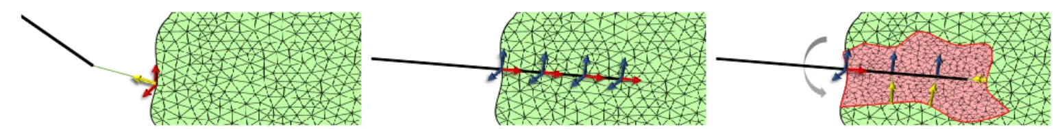
The needle penetration and insertion phases (Figure1aand1b) are similar to [DGM∗09]: when the needle is located outside, a pen-etration constraint(χp, ψp, ψp) is applied between the needle tip
and the closest point located on the triangulated surface. Friction is also added in the tangential plane. Inside the tissue, insertion con-straints(ψi, φi, φi) are added along the path taken by the needle. A
new constraint is created as soon as the needle’s tip is located at a distance diof all the other constraints. Atomic constraints φi
pre-vent lateral motion of the needle along the inserted trajectory, and ψiadds friction along the needle shaft.
4 Needle-tissue cutting and laceration
The cutting phase starts when the average lateral force reaches a cutting force threshold fc, denoted as tearing criteria:
ktik > ni∗ fc, with ti=
∑
nφiλ φi (3)
where niis the number of insertion constraints and ti the initial
direction of the cutting surface.
For each insertion constraint, a point cloud pt of the cut surface
is computed by pt = pi+ dt∗ tiwhere pi are the position of the
insertion constraintsand dt a parameter controlling the extent of
the cutting surface.
The Point-Cloud Library (PCL) [MRB09] is used to generate a tri-angular mesh S from positions of the point cloud. First, a
poly-(a) Penetration constraints: (χp, ψp, ψp) (b) Insertion constraints: (ψi, φi, φi) (c) Cutting constraints: (φc, χc) Figure 1: Needle insertion and cutting: first the needle penetrates the tissue. Then needle/tissue constraints prevent the relative displacements of the models. Finally, in case of lateral motion, the cutting plane is generated from mechanical forces. 3 types of atomic constraints are used: Bilateral atomic constraints (blue), Unilateral atomic constraints (yellow) and Friction atomic constraints (red).
nomial fitting, using Moving-Least Squares, is applied to estimate a normal direction for each point with respect to their neighbors. Then a greedy algorithm is used to triangulate the point cloud into a triangular mesh based on geometrical parameters. These parame-ters are the triangle’s minimal angle θmin, their maximal angle θmax
and maximum surface angle between triangles θs.
During the cutting phase, all the insertion constraints along the needle are removed, except the first insertion point to avoid tear-ing the surface. Instead, a cutttear-ing constraint (φc, χc) is added for all
the needle’s points whose projection is located inside the cutting surface S. The cutting constraints are composed of one Bilateral Atomic Constraint φcbetween needle’s points and their respective
closest point on S. This constraint enforces the needle to slide along the cutting path. In addition, one Unilateral Atomic Constraint χcis
applied between each point located on the border of the cutting sur-face of S and their respective closest point along the needle shaft. If several constraints are associated to the same needle’s edge, only the closest one is kept in order to limit the computational expense. A second mechanical criterion is introduced to extend the cutting path. If any contact force λχcassociated to Unilateral Atomic
Con-straints χcbetween the needle and the border of S reaches a tearing
force threshold ft, the cutting surface is extended in the direction
of the contact normal −nχcat distance dt.
The cutting surface (Figure1c) being extended at different times of the simulation, it must be defined independently from the cur-rent deformation in order to get consistent triangulation of the point cloud over the various extents of the cut. For this purpose the points of S are mapped into the tetrahedral mesh using barycentric coor-dinates. For each new point introduced in the cutting surface S, the position pris computed as follows:
pr= 4
∑
k=1 αk¯q (l) k (4)where l is the index of the tetrahedron containing the point and αk
the associated barycentric coordinate in the deformed state. ¯q(l)k is the nodal position of the tetrahedron l at the initial position. The set of points prprovides a static and undeformed description of the
cutting surface. These positions are used to generate the triangula-tion with PCL, enforcing this way a constant triangulatriangula-tion for all the history of the cut while taking into account new points of the cut. Finally, equation (4) is also applied with the current nodal po-sition of the tissue, providing the popo-sition of the cutting surface in the deformed state on which are applied the interaction constraints. 5 Results and performances
The parameters of the simulations are the distance between con-straints diduring needle insertion, the distance dcbetween points
of the cut surface, and the geometrical parameters for triangular mesh generation θmin, θmaxand θs. In addition, mechanical
param-eters include the Young modulus E and the Poisson ν ratio of both the needle and the volume. The penetration force fp, the cutting
force fc, the tearing force ft, the friction at the surface µpand
dur-ing the insertion µi. Although, the patient-specific identification of
the parameter goes far beyond the scope of this paper, each of them is easily parametrizable in order to obtain the desired behavior for a training simulator.
The method is first evaluated according to the computation time. Since no remeshing is necessary to perform the cut, the computa-tion time is almost not impacted by the model (see Tab.1). A first simulation is performed involving a volume mesh composed of 3072 tetrahedron elements with E = 500kPa and ν = 0.4 to sim-ulate the tissue. The rigid needle’s model is 32cm long composed of 16 beam elements with 0.8cm radius, E = 100GPa and ν = 0.4. In a first phase, a straight needle insertion 17mm places the needle inside the tissue with fp= 0.8N. Then lateral motion of 8mm is
applied to the needle base and tissue tearing is observed when the cutting criteria fc= ft= 1N is reached.
A second experiment is performed where the needle is controlled with a haptic device. During the insertion, the user can feel the var-ious constraints (penetration, friction). When lateral motion is im-posed to the needle’s base, the cut is performed (red surface in Tab.
1) and the user can feel the cutting force necessary to extend the cut. The computation time to solve constraints remains constant for any step of the insertion. During cutting, the most expensive opera-tion is the triangulaopera-tion of the point cloud, representing on average 2 ms. Yet, this procedure is called only for new added points, i.e. every 19.8 time steps on average. At the end, the point cloud was composed of 110 points and a 184 element triangle mesh was gen-erated. The GS requires on average 2.54 iterations during the in-sertion and 80 during the cuting phase. Since the matrices remains very small, the simulation maintains a frame rate of 65 FPS.
Steps Atomic Constraint Total cst. Solving (ms) (ms) Penetration 1 2 (13.2%) 15.1 Insertion 36 3 (19.4%) 15.47
Cutting 12 4 (24.3%) 12
Table 1: Performances for the various steps of the method. The size of the cube is10 cm3. dc= di= 0.5 mm.
An important advantage of the method lies in the fact that the cut surface is generated from mechanical information and not just ge-ometric data. To enhance the importance of this contribution, the
4 P. H. S. Perrusi & P. Baksic & H. Courtecuisse / Interactive Finite Element model of needle insertion and laceration
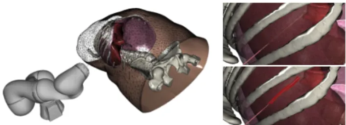
model is employed during a robotic needle insertion inside the liver during the respiratory motion (see Fig.2).
Figure 2: External view of the needle insertion with robotic as-sistance simulation (left). Flexible needle close view (upper right). Rigid needle close view (lower right).
A robotic motion has been precomputed in order to compensate for breathing motion (see [BCDB20]). The needle insertion is performed with both a flexible (Ef lexible = 50GPa) and a rigid
(Erigid= 200GPa) 12cm long needle following the same
precom-puted motion of the robot. As expected, the flexible needle deforms and does not reach the threshold to cut the tissue. Instead, the rigid needle introduces significantly higher stress in the volume, result-ing in the cut of the tissue. The cuttresult-ing path is therefore extended allowing the needle to slide along the cut direction.
6 Conclusion, discussion and future work
This paper introduces an interactive model of needle/tissue inser-tion with the possibility to cut the tissue using mechanical criteria. The cutting path is obtained from the triangulation of a point-cloud whose positions are derived from interaction forces between the needle and the tissue. The method is introduced in the context of training with generic parameters.
In terms of limitations, since the cutting surface is generated on the current deformed state of the tissue, the angle between triangle faces may vary significantly when remapped to the rest state. This is particularly observed when the tissue is significantly deformed and when rapid movements are imposed to the needle during the cutting phase. In this situation, the bilateral constraints can shift their directions rapidly when the needle is sliding through the cut plane and lead to stability issues in the simulation. However, the deformation of organs during percutaneous applications usually re-mains small, limiting the appearance of such instabilities. Sudden drops in the interaction forces were also observed when the contact force reaches the cutting threshold λχc ≥ ft to extend the cutting
surface. However, this effect can be mitigated with the addition of friction constraints along the cutting surface.
Finally, a future direction lies in the possibility to tune the parame-ters based on data provided by a force sensor installed on a robotic system. Drops in the force profile can then be detected to initiate the cut producing this way a patient specific model of the cut.
Acknowledgement: This work was supported by French National Research Agency (ANR) within the project SPERRY ANR-18-CE33-0007 and the Investissements d’Avenir program (ANR-11-LABX-0004, Labex CAMI).
References
[AE10] AL-ELQA. H.: Simulation-based medical teaching and learning. Journal of Family and Community Medicine 17, 1 (jan 2010), 35.1
[AGM∗19] ADAGOLODJOY., GOFFINL., MATHELINM. D., COURTE
-CUISSEH., DEMATHELINM., COURTECUISSEH.: Robotic insertion
of flexible needle in deformable structures using inverse Finite Element simulation. IEEE Transactions on Robotics (2019), 1–12.2
[APM∗16] ABAYAZID M., PACCHIEROTTI C., MOREIRA P., AL
-TEROVITZR., PRATTICHIZZOD., MISRAS.: Experimental evaluation of co-manipulated ultrasound-guided flexible needle steering. Int. Journ. of Med. Robotics and Comp. Assisted Surg. 12, 2 (2016), 219–230.1
[BCDB20] BAKSIC P., COURTECUISSE H., DURIEZC., BAYLE B.: Robotic needle insertion in moving soft tissues using constraint-based inverse Finite Element simulation. IEEE International Conference on Robotics and Automation(2020), 1.4
[BJMB∗14] BAYLEB., JOINIÉ-MAURINM., BARBÉL., GANGLOFFJ., DEMATHELINM.: Robot Interaction Control in Medicine and Surgery: Original Results and Open Problems. In Comp. Surgery and Dual Train-ing. Springer New York, New York, NY, 2014, pp. 169–191.1
[BTB19] BUIH. P., TOMARS., BORDASS. P.: Corotational cut finite element method for real-time surgical simulation: Application to needle insertion simulation. Comput Method Appl M 345 (2019), 183–211.2
[CAK∗14] COURTECUISSEH., ALLARDJ., KERFRIDENP., BORDAS
S. P. A., COTINS., DURIEZC.: Real-time simulation of contact and cut-ting of heterogeneous soft-tissues. Medical Image Analysis 18, 2 (2014), 394–410.2
[CAR∗09] CHENTANEZ N., ALTEROVITZ R., RITCHIE D., CHO L., HAUSERK. K., GOLDBERGK., SHEWCHUKJ. R., O’BRIEN J. F.: Interactive simulation of surgical needle insertion and steering. In ACM SIGGRAPH 2009 Papers(New York,NY,USA, 2009), pp. 88:1–88:10.1
[CLLZ17] CHENGQ. Q., LIUP. X., LAIP. H., ZOU Y. N.: An in-teractive meshless cutting model for nonlinear viscoelastic soft tissue in surgical simulators. IEEE Access 5 (2017), 16359–16371.2
[DGM∗09] DURIEZ C., GUÉBERT C., MARCHAL M., COTIN S., GRISONIL.: Interactive simulation of flexible needle insertions based on constraint models. Lect. Notes in Comp. Sci. (2009), 291–299.1,2
[DS02] DIMAIOS. P., SALCUDEANS. E.: Needle insertion modelling for the interactive simulation of percutaneous procedures. In Lecture Notes in Comp. Sci. (incl. subseries Lecture Notes in AI and Lecture Notes in Bioinfo.)(2002), vol. 2489, Springer Verlag, pp. 253–260.1
[FDA05] FORESTC., DELINGETTEH., AYACHEN.: Removing tetra-hedra from manifold tetratetra-hedralisation: Application to real-time surgical simulation. Medical Image Analysis 9, 2 (2005), 113–122.1
[KBT17] KOSCHIER D., BENDERJ., THUEREYN.: Robust extended finite elements for complex cuting of deformables. ACM Transactions on Graphics 36, 4 (2017).2
[MBF04] MOLINON., BAOZ., FEDKIWR.: A virtual node algorithm for changing mesh topology during simulation. In ACM SIGGRAPH 2004 Papers(New York, NY, USA, 2004), ACM, pp. 385–392.2
[MRB09] MARTONZ. C., RUSUR. B., BEETZM.: On Fast Surface Reconstruction Methods for Large and Noisy Datasets. In Proceedings of the IEEE ICRA(Kobe, Japan, 2009).2
[Pat12] PATRICIUA.: CUDA accelerated simulation of needle insertions in deformable tissue. Journal of Physics: Conf. Series 385, 1 (2012).1
[PBB∗09] PICCIN O., BARBÉ L., BAYLE B., DE MATHELIN M., GANGIA.: A Force Feedback Teleoperated Needle Insertion Device for Percutaneous Procedures. The International Journal of Robotics Re-search 28, 9 (2009), 1154–1168.1
[PUC∗15] PAULUSC. J., UNTEREINERL., COURTECUISSEH., COTIN
S., CAZIERD.: Virtual cutting of deformable objects based on efficient topological operations. The Visual Comp. 31, 6-8 (2015), 831–841.2
[SLLW18] SIW., LUJ., LIAOX., WANGQ.: Towards Interactive Pro-gressive Cutting of Deformable Bodies via Phyxel-Associated Surface Mesh Approach for Virtual Surgery. IEEE Access 6 (2018).2
[WM18] WANGM., MAY.: A review of virtual cutting methods and technology in deformable objects. The International Journal of Medical Robotics and Computer Assisted Surgery 14, 5 (2018), e1923.1