THE CAUSES AND CONSEQUENCES OF DIVERGENCE
BETWEEN THE AIR TRAFFIC CONTROLLER STATE
AWARENESS AND ACTUAL SYSTEM STATE
Brandon R. Abel and R. John Hansman
This report is based on the Doctoral Dissertation of Brandon R. Abel submitted to the Aeronautics and Astronautics Division in partial fulfillment of the requirements for the degree of
Doctor of Philosophy at the Massachusetts Institute of Technology. The work presented in this report was also conducted in collaboration with the members of the Doctoral Committee:
Prof. R. John Hansman (Chair) Dr. Wes A. Olson Prof. Julie A. Shah
Report No. ICAT-2017-07 September 2017
MIT International Center for Air Transportation (ICAT) Department of Aeronautics & Astronautics
Massachusetts Institute of Technology Cambridge, MA 02139 USA
THE CAUSES AND CONSEQUENCES OF DIVERGENCE
BETWEEN THE AIR TRAFFIC CONTROLLER STATE
AWARENESS AND ACTUAL SYSTEM STATE
byBrandon R. Abel and Prof. R. John Hansman
A
BSTRACT
ivergence is an inconsistency between the human’s system state awareness and the actual system state. This research investigated divergence potential in air traffic controllers and identified controller divergence causes and consequences. Based on this investigation, approaches to minimize controller divergence and its consequences were identified for current air traffic control systems and future systems where unmanned aircraft will be integrated.
Prior studies identified pilot divergence as a factor in several recent aircraft accidents and could be a factor for controllers. The future addition of unmanned aircraft in national airspace is a significant change which will affect the pilot and controller relationship and presents an opportunity to consider divergence before procedures are developed.
To understand how to minimize divergence and its consequences, this research developed a divergence cause and consequence framework and a cognitive process framework. The cause and consequence framework was developed using established risk analysis methods. The cognitive process framework was developed using established cognitive process and human error approaches. This research refined these frameworks and demonstrated their utility in an investigation of historical air traffic control accidents. They were then used to identify divergence vulnerabilities in a future unmanned aircraft-integrated national airspace.
Air traffic control cases were analyzed between 2011 and 2015 using the framework to understand causes and consequences of controller divergence. Twenty-seven (sixty-four percent) of these cases contained controller divergence contributing to the hazardous consequence. Although divergence causes and states varied, the most common event
sequence included a diverged controller inducing an aircraft-to-aircraft conflict. These cases provided insight for system mitigations to reduce divergence causes and the consequentiality should it occur.
The potential emergence of controller divergence with the integration of unmanned aircraft in national airspace was then investigated. Field studies of controllers experienced managing unmanned aircraft identified important differences between manned and unmanned aircraft. The framework was then used to analyze these potential divergence vulnerabilities. Observables, specifically intent, appear more challenging to perceive yet crucial for controller projection of unmanned aircraft position due to their lack of onboard human perception, lost link, and automated operations. Hazardous consequences may be more likely due to the inability for unmanned aircraft to provide mitigations.
A
CKNOWLEDGEMENTS
This material is based upon work supported under Air Force Contract No. FA8721-05-C-0002 and/or FA8702-15-D-0001.
TABLE OF CONTENTS
1 INTRODUCTION ... 19
1.1 Divergence ... 19
1.2 Motivation ... 20
1.3 Research Objective, Scope, and Focus ... 22
1.3.1 Scope: Air Traffic Controller Divergence Controlling Manned and Unmanned Aircraft ... 22
1.3.2 Focus: Causes of Divergence ... 23
1.3.3 Focus: Consequences of Divergence ... 24
1.4 Research Approach ... 24
2 AIR TRAFFIC CONTROL SYSTEM ... 26
2.1 National Airspace System ... 26
2.2 Air Traffic Control ... 29
2.2.1 Air Traffic Control Facilities ... 29
2.2.2 Air Traffic Controller Division of Labor ... 32
2.2.3 Air Traffic Control Tasks ... 33
2.2.4 Air Traffic Control Stations and Structure ... 33
2.3 Unmanned Aircraft Systems Background ... 34
2.3.1 Unmanned Aircraft System Elements ... 35
2.3.2 Unmanned Aircraft System Categorization ... 36
2.3.3 Unmanned Aircraft System Characteristics ... 37
2.3.4 Unmanned Aircraft System Integration Challenges from Literature ... 38
3 LITERATURE REVIEW ... 40
3.1 Human Information Processing ... 40
3.2 Situation Awareness ... 46
3.3 Human Error ... 48
3.4 Risk Analysis and Accident Causation ... 54
3.5 Summary ... 59
4 AIR TRAFFIC CONTROLLER DIVERGENCE CAUSE AND CONSEQUENCE FRAMEWORK ... 61
4.1 Development of the Cause and Consequence Framework ... 61
4.1.1 Framework Developed from Literature ... 61
4.1.2 Framework Developed from Case Study Analysis ... 62
4.1.3 State ... 63
4.1.4 Actual System State ... 63
4.1.5 Controller State Awareness ... 64
4.2 Development of the Air Traffic Controller Cognitive Process Framework ... 66
4.2.1 Framework Developed from Literature ... 66
4.2.2 Framework Refined through Case Study Analysis ... 66
4.3 Air Traffic Controller Cognitive Process Framework ... 67
4.3.1 State Assessment Process ... 68
4.3.2 Decision Process ... 78
4.3.3 Execution Process ... 81
5 FRAMEWORK TO UNDERSTAND THE CAUSES OF DIVERGENCE ... 83
5.1 Incorrect Outputs of the State Assessment Process ... 85
5.1.1 Incorrect Outputs of the Perception Process ... 85
5.1.2 Incorrect Outputs of the Comprehension Process ... 88
5.1.3 Incorrect Outputs of the Projection Process ... 91
6 FRAMEWORK TO UNDERSTAND THE CONSEQUENCES OF DIVERGENCE ... 94
6.1 Consequential and Inconsequential Divergence ... 94
6.2 Hazardous Actions ... 95
6.2.1 Decision and Execution Process Consequences ... 96
6.2.2 Decision and Execution Consequences to the Cause and Consequence Framework 97 6.3 Potentially Hazardous Situation ... 98
6.4 Mitigations for the Consequences of Divergence ... 99
6.4.1 Controller Mitigations for the Consequences of Divergence ... 99
6.4.2 System Mitigations for the Consequences of Divergence ... 102
6.4.3 Mitigations to Make an Otherwise Consequential Divergence Inconsequential .... 103
6.5 Final Consequences ... 104
7 AIR TRAFFIC CONTROL CASE STUDY METHODOLOGY ... 105
7.2 Accident and Incident Case Studies of Controller Divergence ... 105
7.3 Case Study Research Method ... 109
7.3.1 Step 1 – Identify divergence, divergence type, divergence state, and re-convergence 109 7.3.2 Step 2 – Identify the causes of divergence ... 112
7.3.3 Step 3 – Identify the consequences of divergence ... 113
7.3.4 Step 4 – Identify potential mitigations ... 115
7.3.5 Case study limitations ... 116
7.4 Example Case Study Analysis – Case #23 ... 116
7.4.1 Case #23 – Divergence type, divergence state, and re-convergence ... 117
7.4.2 Case #23 – The causes of divergence ... 118
7.4.3 Case #23 – The consequences of divergence ... 119
7.4.4 Case #23 – Potential mitigations ... 120
8 AIR TRAFFIC CONTROL CASE STUDY ANALYSIS OF RESULTS ... 123
8.1 Accident and Incident Case Overview ... 123
8.1.1 Identified Hazardous Consequences ... 123
8.1.2 Identified Root Diverged States ... 124
8.2 Identified Divergence Causes and Mitigations ... 125
8.2.1 Identified Perception Process Failures ... 126
8.2.2 Identified Comprehension Process Failures ... 131
8.2.3 Identified Working Memory Failures ... 134
8.2.4 Identified Projection Process Failures ... 135
8.2.5 Identified Divergence Summary ... 137
8.3 Identified Divergence Consequences and Mitigations ... 138
8.3.1 Identified Hazardous Actions ... 139
8.3.2 Identified Potentially Hazardous Situations ... 141
8.3.3 Identified Mitigations After Divergence ... 142
8.3.4 Identified Hazardous Consequences ... 148
8.4 Accident and Incident Case Summary ... 149
9 CURRENT AIR TRAFFIC CONTROL UNMANNED AIRCRAFT SYSTEMS FIELD
STUDY ... 153
9.1 Field Study Approach ... 153
9.1.1 Field Study Method ... 154
9.2 Field Study Results ... 160
9.2.1 Policies and Procedures ... 160
9.2.2 Important Aircraft and Operator Differences ... 163
9.2.3 Scenario-Based Questions ... 167
10 IMPLICATIONS FOR FUTURE UNMANNED AIRCRAFT SYSTEMS-NATIONAL AIRSPACE SYSTEM INTEGRATION ... 171
10.1 Lack of Onboard Human Perception ... 171
10.1.1 Divergence Vulnerabilities from Lack of Onboard Human Perception ... 171
10.1.2 Potential Mitigations for the Lack of Onboard Human Perception ... 173
10.2 Lost Link ... 175
10.2.1 Controller Divergence Vulnerabilities from Lost Link ... 175
10.2.2 Current UAS Procedures for Lost Link ... 177
10.2.3 Potential Mitigations for Lost Link ... 179
10.3 UAS Flight Characteristics ... 182
10.3.1 UAS Flight Profiles – More Complex or Less Structured Routes ... 182
10.3.2 UAS Flight Operations – Static, Long-Duration Missions ... 186
10.3.3 UAS Performance Characteristics – Low Speeds and Increased Maneuverability 189 10.4 Levels of Control Automation ... 192
10.4.1 Opportunities and Divergence Vulnerabilities from Various Levels of Control Automation ... 192
10.4.2 Potential Mitigations for Various Levels of Control Automation ... 194
10.5 Summary ... 195
10.5.1 Implications for Future UAS-Integration ... 195
11 CONCLUSIONS ... 200
11.1 Air Traffic Controller Divergence Cause and Consequence Framework ... 200
11.3 Air Traffic Control Case Study Analysis ... 202 11.4 Unmanned Aircraft Systems Investigation ... 204 11.4.1 Air Traffic Control Unmanned Aircraft System Field Study ... 204 11.4.2 Implications for Future Unmanned Aircraft System National Airspace System Integration ... 204 11.5 Future Work ... 205
TABLE OF FIGURES
Figure 1-1. Global Aerial Drone Market (BI Intelligence, 2016). ... 21
Figure 1-2. Simplified Input-Process-Output model ... 23
Figure 2-1. Airspace depiction. ... 29
Figure 2-2. NAS ARTCC facilities (VATSIM Cleveland ARTCC, 2017). ... 30
Figure 2-3. NAS TRACON and RAPCON facilities (North America Region Training Academy, 2017). ... 31
Figure 2-4. Typical flight profile (Aviation Stack Exchange, 2017). ... 32
Figure 2-5. UAS architectural elements. ... 35
Figure 2-6. DoD UAS group descriptions (Department of Defense, 2011). ... 36
Figure 3-1. Three stages of information processing, adapted from (Proctor & Van Zandt, 2008). ... 41
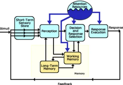
Figure 3-2. Wickens, Hollands, Banbury, & Parasuraman (2013) model of human information processing as in (FAA, 2016). ... 42
Figure 3-3. Histon’s cognitive process model of an air traffic controller (Histon, 2008). ... 45
Figure 3-4. Endsley's model of situation awareness in dynamic decision making (Endsley M. R., 1995). ... 47
Figure 3-5. Levels of performance of skilled human operators (Rasmussen, 1983). ... 50
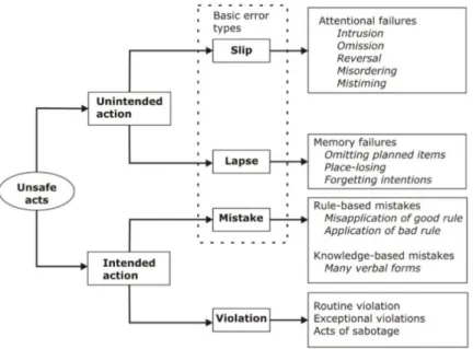
Figure 3-6. A classification of unsafe acts (Reason, 1990). ... 51
Figure 3-7. Human state assumption and divergence profile through time (Silva, 2016). ... 53
Figure 3-8. Human information processing model of divergence (Silva, 2016). ... 54
Figure 3-9. The five factors in the accident sequence (Klockner & Toft, 2015). ... 54
Figure 3-10. Human contributions to accidents (Reason, 1990). ... 55
Figure 3-11. The dynamics of accident causation (Reason, 1990). ... 55
Figure 3-12. Typical control loop and the process models involved in a system (Leveson N. , 2004). ... 56
Figure 3-13. A simplified fault tree (NASA Office of Safety and Mission Assurance, 2002). .... 58
Figure 3-14. A simplified event tree (Resilinc, 2016). ... 58
Figure 3-15. Bowtie method diagram, adapted from (Fisher, Ebrahim, & Sun, 2013). ... 59
Figure 4-2. Divergence causes and consequences represented using a bowtie method diagram. 62
Figure 4-3. The air traffic controller cognitive process framework. ... 67
Figure 4-4. Perception process representation. ... 69
Figure 4-5. Comprehension process representation. ... 72
Figure 4-6. Traditional dynamic system. ... 76
Figure 4-7. Projection process representation. ... 76
Figure 4-8. Decision process representation. ... 78
Figure 4-9. Possible discrete states of controller awareness. ... 80
Figure 4-10. Execution process representation. ... 82
Figure 5-1. Air traffic controller cognitive process framework. ... 83
Figure 5-2. Air traffic controller divergence cause and consequence framework. ... 84
Figure 6-1. Air traffic controller divergence cause and consequence framework. ... 94
Figure 6-2. Decision and execution processes in the air traffic controller cognitive process framework. ... 96
Figure 6-3. Controller mitigations for the consequences of divergence. ... 100
Figure 6-4. Typical transition of state awareness. ... 101
Figure 6-5. Re-convergence without typical lengths of known divergence. ... 102
Figure 6-6. Aircraft right-of-way rules (planefinder, 2017). ... 103
Figure 7-1. Case study preliminary analysis decomposition (N=42). ... 106
Figure 7-2. ASDE-X screen capture (National Trasnportation Safety Board, 2012). ... 110
Figure 7-3. Communication transcript (Federal Aviation Administration, 2013). ... 110
Figure 7-4. Air traffic controller divergence cause and consequence framework. ... 112
Figure 7-5. Backward propagation from divergence to its mechanism. ... 113
Figure 7-6. Air traffic controller divergence cause and consequence framework. ... 114
Figure 7-7. Screen capture of the Ocean21 display at the approximate time of AAL183’s clearance to climb (National Transportation Safety Board, 2015). ... 117
Figure 8-1. Twenty-nine (29) hazardous consequences from 29 potentially hazardous situations. ... 124
Figure 8-2. Case study distribution of process and memory failures. ... 126
Figure 8-3. Sources of perception process failures. ... 127
Figure 8-5. Agent observables and divergence propagation. ... 129
Figure 8-6. Sources of comprehension process failures. ... 131
Figure 8-7. Airspeed points (Chadwick, 2013). ... 137
Figure 8-8. Predictive aiding (Eurocontrol, 2017). ... 137
Figure 8-9. “No Action” leading to a potentially hazardous situation. ... 139
Figure 8-10. “Incorrect Actions” leading to a potentially hazardous situation. ... 140
Figure 8-11. Controller conflict alert effectiveness. ... 143
Figure 8-12. Pilot conflict alert effectiveness. ... 146
Figure 8-13. Percentage of instances of process failures. ... 149
Figure 9-1. USAF CONUS UAS locations (USAF, 2017). ... 155
Figure 9-2. MQ-1B Predator (Defense Media Acitivity, 2015). ... 156
Figure 9-3. MQ-9 Reaper (Defense Media Activity, 2015). ... 156
Figure 9-4. RQ-4 Global Hawk (Defense Media Activity, 2015). ... 156
Figure 9-5. Edwards Air Force Base (AFB) control tower supervisor's station. ... 158
Figure 9-6. Initial responses for the differences between manned and unmanned aircraft (N=37). ... 163
Figure 9-7. Follow-up responses for the differences between manned and unmanned aircraft (N=37). ... 164
Figure 9-8. Ranked performance differences between manned and unmanned aircraft (N=35). 165 Figure 9-9. Anticipation of unmanned aircraft compared to manned aircraft. ... 166
Figure 9-10. Manned and unmanned aircraft approaching. ... 167
Figure 9-11. Controller choice of who to maneuver, aggregate non-urgent case (N = 80). ... 168
Figure 9-12. Controller’s choice of who to maneuver, aggregate urgent case (N = 80) ... 168
Figure 9-13. Factors influencing a controller's decision on who to maneuver. ... 168
Figure 10-1. Vulnerabilities due to a lack of onboard human perception. ... 173
Figure 10-2. Vulnerabilities due to lost link. ... 176
Figure 10-3. Lost link conditional routing (Eurocontrol, 2010). ... 178
Figure 10-4. Current nominal lost link intent observable architecture. ... 180
Figure 10-5. Ineffective lost link intent observable architecture. ... 180
Figure 10-6. Proposed UA LL observable communication architecture. ... 180
Figure 10-8. Grid pattern (UAS Magazine, 2017). ... 183
Figure 10-9. Vulnerabilities due to UAS flight profiles. ... 184
Figure 10-10. Segregated area abstractions. ... 185
Figure 10-11. Additional waypoint structure. ... 186
Figure 10-12. Notional aircraft with zero groundspeed. ... 187
Figure 10-13. Vulnerabilities due to atypical flight operations. ... 188
Figure 10-14. Notional increased maneuverability on the TSD. ... 190
Figure 10-15. Implications for atypical performance characteristics. ... 191
Figure 10-16. Mandated airspeed points during arrival sequencing (Civil Aviation Department, 2017). ... 191
Figure 10-17. Vulnerabilities due to fully autonomous and adaptive control automation. ... 193
LIST OF TABLES
Table 1-1. Research approach overview. ... 25
Table 3-1. Classifying the primary error types, adapted from (Reason, 1990). ... 49
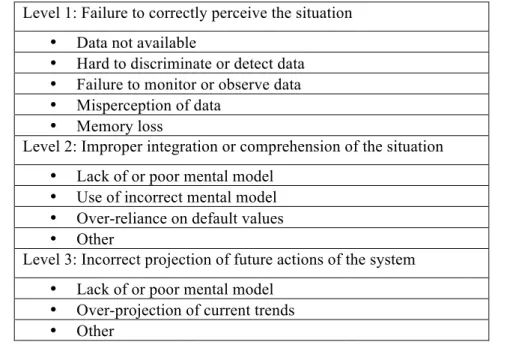
Table 3-2. Taxonomy of levels of situation awareness errors, adapted from (Jones D. G., 1997). ... 52
Table 7-1. Case dataset (N=27). ... 108
Table 8-1. Root Diverged States. ... 125
Table 8-2. Case study results. ... 138
Table 8-3. Hazardous actions and potentially hazardous situations. ... 141
Table 8-4. Potentially Hazardous Situations. ... 142
Table 8-5. Instances of transitions to known divergence and re-convergence. ... 143
Table 8-6. Root diverged states, potentially hazardous situations, and hazardous consequences. ... 148
Table 9-1. Field site visit facilities. ... 156
Table 9-2. Phone interviews conducted. ... 160
LIST OF ACRONYMS
AAL American AirlinesAAR Aviation Accident Report
ACAS Airborne Collision Avoidance System ADD Aircraft-Derived Data
ADS-B Automatic Dependent Surveillance-Broadcast AFB Air Force Base
AFI Air Force Instruction AGL Above Ground Level
AMASS Airport Movement Area Safety System ARTCC Air Route Traffic Control Center ARTS Automated Radar Terminal System
ASDE-X Airport Surface Detection Equipment model X ASR Airport Surveillance Radar
ASRS Air Route Surveillance Radar ATC Air Traffic Control
ATCo Air Traffic Controller ATCT Air Traffic Control Tower ATM Air Traffic Management
ATOP Advanced Technologies and Oceanic Procedures BAFBI Beale Air Force Base Instruction
BLOS Beyond Line Of Sight
CA Conflict Alert
CAFBI Creech Air Force Base Instruction CAL China Airlines
CAST Commercial Aviation Safety Team CFIT Controlled Flight Into Terrain CFR Code of Federal Regulations COA Certificates of Authorization CONOPS Concept of Operations CONUS Continental United States
CPDLC Controller-Pilot Data Link Communications
CS Control Station
CTAF Common Traffic Advisory Frequency CTAS Center-TRACON Automation System CVR Cockpit Voice Recorder
DoD Department of Defense DoT Department of Transportation DVE Degraded Visual Environment EAFBI Edwards Air Force Base Instruction
EGPWS Enhanced Ground Proximity Warning System ERAM En Route Automation Modernization
ETA Event Tree Analysis
EVO Equivalent Visual Operations FAA Federal Aviation Administration
FAR Federal Aviation Regulation FDR Flight Data Recorder
FL Flight Level
FLM Front Line Manager FPS Flight Progress Strips FTA Fault Tree Analysis
GAO Government Accounting Office GPS Global Positioning System
GPWS Ground Proximity Warning System HAFBI Holloman Air Force Base Instruction HATR Hazardous Air Traffic Report
HFACS Human Factors Analysis and Classification System HIP Human Information Processing
ICAO International Civil Aviation Organization IFR Instrument Flight Rules
IMC Instrument Meteorological Conditions IPO Input-Process-Output
KAL Korean Airlines
LL Lost Link
LOS Line Of Sight
LoSS Loss of Standard Separation MAC Mid-Air Collision
MOA Military Operations Area MRU Military Radar Unit
MSAW Minimum Safe Altitude Warning MSL Mean Sea Level
MVA Minimum Vectoring Altitude NAFBI Nellis Air Force Base Instruction NAS National Airspace System
NASA National Aeronautics and Space Administration NATO North Atlantic Treaty Organization
NextGen Next Generation Air Transportation System NMAC Near Mid-Air Collision
NORDO No Radio
NOTAM Notices To Airmen
NTSB National Transportation Safety Board
PARC Performance-based operations Aviation Rulemaking Committee PIREP Pilot Report
RA Resolution Advisory
RAPCON Radar Approach Control
RF Radio Frequency
RPA Remotely Piloted Aircraft
RVSM Reduced Vertical Separation Minima
SA Situation Awareness
SAA Sense-And-Avoid
SOP Standard Operating Procedures SSR Secondary Surveillance Radar
STAMP Systems-Theoretic Accident Model and Processes STANAG Standardization Agreement
STCA Short Term Conflict Alert SUA Special Use Airspace
TA Traffic Advisory
TAS Traffic Advisory System
TCAS Traffic Collision and Avoidance System TRACON Terminal Radar Approach Control TSD Traffic Situation Display
UA Unmanned Aircraft
UAS Unmanned Aircraft System
UASO Unmanned Aircraft System Operator
US United States
USAF United States Air Force UTM UAS Traffic Management VFR Visual Flight Rules VLO Visual Look Out VLOS Visual Line Of Sight
VMC Visual Meteorological Conditions WAIT Work Accidents Investigation Technique
WG Working Group
1 INTRODUCTION
Divergence is an inconsistency between the human’s system state awareness and the actual
system state (Silva, 2016). Inconsistencies between air traffic controllers and the system they control was highlighted as a vulnerability to safety risk within the Air Traffic Control (ATC) community (Performance-based operations Aviation Rulemaking Committee/Commercail Aviation Safety Team Flight Deck Automation Working Group, 2013), and has been shown to be a contributing factor in many recent aircraft accidents (Silva, 2016). This research hypothesizes controller divergence is a major risk area in the National Airspace System (NAS). At the same time, integrating Unmanned Aircraft Systems (UAS) in the NAS is a significant change which will affect the relationship between pilots and controllers and may also create opportunities for divergence. This research attempts to understand how to minimize controller divergence while they manage a human-integrated system by examining divergence causes and consequences in the ATC domain. To accomplish this objective, a framework of the causes and consequences of air traffic controller divergence was developed along with a framework of air traffic controller cognitive processes. The utility of these frameworks was demonstrated with an historical case study investigation. The frameworks were then used to identify opportunities and divergence vulnerabilities in a future system, an UAS-integrated NAS.
1.1 D
IVERGENCE
Divergence is formally defined as an inconsistency between the human’s system state
awareness and the actual system state (Silva, 2016). Human understanding while operating a complex system, from driving a car to flying an airplane or managing a factory is seldom perfect. Luckily, perfection is seldom required. First of all, some system states do not need to be understood. For example, a radar air traffic controller does not need to know an airplane’s color to effectively control it. Also, some system states only need to be imprecisely understood. While ATC displays present ground speed to the controller, a two-knot ground speed error is not likely to adversely affect the controller’s ability to manage aircraft or adversely affect the overall system. Finally, divergence may not lead to negative consequences in all situations. For instance, an aircraft not flying at their clearance altitude is only hazardous when another aircraft or obstacle is in conflict with it. Therefore, this research is concerned with consequential divergence.
Consequential divergence is defined as divergence which is substantial enough in a task
relevant state and consequential situation to affect the outcome of the situation. Conversely,
inconsequential divergence is divergence which is either not substantial enough, not in a task
relevant state, or not in a consequential situation to adversely affect the outcome of the situation. For the remainder of this paper, the term ‘divergence’ will be used rather than the phrase ‘consequential divergence’; the ‘consequential’ will be assumed.
To clarify the divergence definition, state will be defined as a set of variables used to describe a dynamic system as a function of time. State could be considered a vector, with variables. As described earlier, not all state variables are relevant. The
task relevant state will be defined as a subset of the total state vector relevant for the human’s
particular task. Furthermore, a consequential situation will be defined as a situation which could have a reasonable chance of leading to a hazardous consequence.
Divergence can also be decomposed into different types depending upon the human’s awareness. First, the human may experience unknown divergence (Silva, 2016), where the human assumes that their system state awareness is consistent with the actual system state, but it is not. The human may also experience known divergence (Silva, 2016), where the human has awareness that their assumed system state is not consistent with the actual system state. When humans experience unknown divergence, they will make decisions and execute actions based on inconsistent state awareness. However, when they experience known divergence, they may make decisions and execute actions to resolve their divergence and re-converge. Re-convergence is where the human has been diverged but has since aligned their system state awareness with the actual system state (Silva, 2016).
1.2 M
OTIVATION
Many recent aircraft accidents involve divergence between the aircrew state awareness and the actual system state (Silva, 2016). While Silva’s work centered on pilot auto-throttle mode confusion and sought to understand divergence in a historical context, a recent Performance-based operations Aviation Rulemaking Committee (PARC)/Commercial Aviation Safety Team (CAST) Flight Deck Automation Working Group (WG) report highlighted areas of concern within the ATC community regarding inconsistent awareness. The report suggested areas of vulnerabilities with human error and misunderstanding, including communication and
coordination between pilots and air traffic services, Standard Operating Procedures (SOP), and air traffic service personnel’s knowledge of aircraft capabilities (Performance-based operations Aviation Rulemaking Committee/Commercail Aviation Safety Team Flight Deck Automation Working Group, 2013). While divergence between controllers and pilots has likely existed since the inception of the NAS, Silva’s work had yet to be extended to the ATC domain with a formal investigation of controller divergence.
The NAS is currently undergoing a unique change which will affect the relationship between pilots and controllers, the addition of UAS. There is an emerging need for UAS integration in the NAS. The global market for UAS is forecasted to grow substantially in the coming years, shown in Figure 1-1, with North America forecasted to occupy 32 percent of the military market (PRNewswire, 2017) and the US to source some 60 percent of the total market (COTS Journal, 2017).
Figure 1-1. Global Aerial Drone Market (BI Intelligence, 2016).
Not only is the UAS market projection driving the need for integration, the Federal Aviation Administration (FAA) Modernization and Reform Act of 2012 mandated federal agencies to develop a comprehensive plan to employ UAS in the NAS within 270 days (House of Representatives, 2012), leading to the UAS Comprehensive Plan (Joint Planning and Development Office, 2013). The inevitable increase of UAS operations in the NAS provides an opportunity to analyze and potentially mitigate controller divergence.
This analysis is vital because the current NAS is designed around manned aircraft (Joint Planning and Development Office, 2012), which are different than Unmanned Aircraft (UA). The differences between manned and unmanned aircraft may increase the likelihood of divergence among controllers managing UAS in the NAS. In fact, many federal agencies and researchers have shown human-system integration concerns with UAS. These concerns include communication and control links, contingency procedures associated with these links, such as lost link (FAA, 2012; Federal Aviation Administration, 2013; Comstock Jr., McAdaragh, Ghatas, Burdette, & Trujillo, 2014; Yuan & Histon, 2014),1 UAS interaction with the Air Traffic Management (ATM) system (FAA, 2012), and operator sensory differences (Federal Aviation Administration, 2013). Therefore, understanding controller divergence may help inform UAS-integrated NAS procedures and architectures to reduce the likelihood and consequences of controller divergence before UAS-integration occurs.
1.3 R
ESEARCH
O
BJECTIVE
,
S
COPE
,
AND
F
OCUS
The overall objective of this research is to understand divergence and its consequences in human controllers while they manage a human-integrated system and how to minimize them. To accomplish this objective, the research examined the causes of divergence in a human-integrated system and how that divergence became consequential. This examination provided insight for design mitigations to reduce or eliminate the causes of divergence and the factors contributing to its consequential nature.
1.3.1 Scope: Air Traffic Controller Divergence Controlling Manned and
Unmanned Aircraft
The ATC domain is characterized by the management of multiple spatially-separated agents requiring the comprehension of states and their projection into the future to accomplish the human agent’s goals, primarily safety. This management is predominantly accomplished by an air traffic controller, a human agent that perceives system observables and affects the system by commanding or recommending actions to other system agents. Therefore, there is potential for divergence during the execution of a controller’s tasks. While this research is specific to the
1 Lost link is defined as “an interruption or loss of the control link, or when the pilot is unable to effect control of the
aircraft and, as a result, the UA will perform a predictable or planned maneuver. Loss of command and control link between the Control Station and the aircraft” (Federal Aviation Administration, 2015).
ATC domain, it is hypothesized to generalize to other domains where humans require state knowledge to manage dynamic situations.
A portion of the research examined case studies, aided by a developed air traffic controller divergence cause and consequence framework and an air traffic controller cognitive process framework. These case studies, all controller-related aviation accidents and incidents, involved only manned aircraft. However, this research capitalized on the unique opportunity of UAS integration and analyzed a future UAS-integrated NAS before the system is fully developed. By examining this system before fielding, the goal is to provide a framework to influence the design to reduce or eliminate controller divergence or divergence consequentiality. The research focused on two major aspects of divergence within the ATC domain – the causes of controller divergence and how the divergence becomes consequential in the situation. Additionally, the analysis informed development of mitigations to reduce or eliminate divergence within the system.
1.3.2 Focus: Causes of Divergence
A focus of the research was to examine the causes of controller divergence. Although divergence occurs in human cognitive processes, the cause of the divergence could originate in numerous areas of cognition or from outside the human altogether. The cognitive process framework is based on an Input-Process-Output (IPO) model; a simplified model is shown in Figure 1-2.
Figure 1-2. Simplified Input-Process-Output model
In Figure 1-2 an incorrect output value could occur from either an incorrect input value to the process or a failure in the processes itself. This research examined the causes of controller divergence using accident and incident case studies leading to hazardous consequences. In addition, it investigated a future UAS-integrated NAS to identify controller opportunities and divergence vulnerabilities.
1.3.3 Focus: Consequences of Divergence
The second research focus was to examine how controller divergence becomes consequential. Divergence becomes consequential when it is substantial in a task relevant state and consequential situation. Specifically, a divergence in the process may not be large enough to lead to an incorrect output or the diverged state may not be required to produce an output. Furthermore, even if the output is incorrect, it may not lead to a hazard in the system.
After investigating controller divergence both in terms of causality and consequentiality, the research identified areas of divergence mitigations. Divergence can be mitigated in the ATC system in two basic ways. Divergence can either be reduced or eliminated prior to its occurrence, or the consequences of divergence can be reduced or eliminated once it has
occurred. Divergence mitigations may be in the form of hardware or software designs, increased
communications, or new SOP. Regardless, mitigations should target the diverged state and the process leading to its assessment.
1.4 R
ESEARCH
A
PPROACH
To accomplish the overall objective, this research was informed by prior work on risk analysis to develop an air traffic controller divergence cause and consequence framework. To better understand the causes and cognitive consequences of controller divergence, this research was informed by prior work on human cognition to develop an air traffic controller cognitive process framework. Next, this research used the frameworks to examine controller divergence in historical case studies of ATC accidents and incidents. Case studies were examined to refine the frameworks, understand the causes and consequence of controller divergence, and provide insight to propose mitigations to reduce or eliminate controller divergence or divergence consequentiality in ATC. Finally, if the causes and consequences of controller divergence are understood early in the implementation of major changes to the NAS, insight gained can be used to reduce or eliminate the causes and consequences of controller divergence, with the goal of reducing or eliminating hazardous consequences. Therefore, to demonstrate the utility of the frameworks, a potential future operating system and environment was analyzed for controller opportunities and divergence vulnerabilities. This research used an UAS-integrated NAS as an example future system to accomplish the task. Table 1-1 below summarizes this approach.
Table 1-1. Research approach overview.
Divergence Causes Divergence Consequences Theory
• Divergence Cause and Consequence Framework • Cognitive Process
Framework
• Divergence Cause and Consequence Framework • Cognitive Process
Framework
Historical
Context • Accident/Incident Case Studies • Accident/Incident Case Studies
Future
Context • UAS-Integrated NAS • UAS-Integrated NAS
Specifically, research objectives corresponding to the approach outlined in Table 1-1 are the following:
Objective 1. Develop a framework to help identify causes and consequences of divergence in air traffic controller cognitive processes and controller-system integration.
Objective 2. Utilize the air traffic controller divergence cause and consequence framework and air traffic controller cognitive process framework as tools to understand causes of air traffic controller divergence in air traffic control accident and incident case studies.
Objective 3. Utilize the air traffic controller divergence cause and consequence framework and air traffic controller cognitive process framework as tools to understand consequences of air traffic controller divergence in air traffic control accident and incident case studies.
Objective 4. Utilize the air traffic controller divergence cause and consequence framework and air traffic controller cognitive process framework as tools to identify controller opportunities and divergence vulnerabilities within a UAS-integrated NAS.
Using this approach, the research developed insight into controller divergence from a human-integrated systems perspective. This approach provided understanding of both the cognitive capabilities and limitations of the human controller and the system capabilities and limitations which can affect human divergence. With this understanding, effective mitigations can be targeted at critical system deficiencies or transformable human limitations.
2 AIR TRAFFIC CONTROL SYSTEM
To minimize divergence and its consequences in human controllers while they manage a human-integrated system, it is important to understand the system’s operational context and the air traffic controller’s task.2 The ATC system’s primary purpose is to prevent a collision between aircraft operating in the system and to provide a safe, orderly, and expeditious flow of traffic (Federal Aviation Administration, 2015). The system also has the capability to provide additional services based on traffic volume, frequency congestion, radar quality, controller workload, duty priorities, and other human limitations (Federal Aviation Administration, 2015). The FAA created this system to protect passengers and crew, persons and property on the ground and to establish a safe and efficient airspace environment for civil, commercial, and military aviation (Federal Aviation Administration, 2007). To accomplish the ATC system’s purpose, controllers must be converged in their task relevant states. This chapter will present background on the NAS, ATC, and UAS.
2.1 N
ATIONAL
A
IRSPACE
S
YSTEM
To aid in accomplishing the ATC system’s purpose, the FAA has developed a NAS with multiple layers of structure. The NAS is a network of air navigation facilities, ATC facilities, airports, technology, and appropriate rules and regulations needed to operate the system (Federal Aviation Administration, 2007). This structure assists the controller managing the system in many ways, particularly for this research, by helping the controller remain converged with the system.3
To begin, weather conditions constrain the flight rules under which aircraft can operate and also affect aircraft separation standards (i.e. the distance allowed between aircraft during flight).4 Aircraft operate under two distinct categories of operational flight rules: Visual Flight Rules (VFR) and Instrument Flight Rules (IFR). These two flight rules are linked to two categories of weather conditions: Visual Meteorological Conditions (VMC) and Instrument Meteorological Conditions (IMC). During VMC aircraft may operate under VFR, during which the pilot is primarily responsible for seeing other aircraft and maintaining safe separation. During IMC
2 For a comprehensive review of the ATC system, see Nolan’s Fundamentals of Air Traffic Control (Nolan, 2010). 3 Structure’s importance in ATC is discussed in 3.1 Human Information Processing with research by Histon (2008). 4 Required aircraft separation is dependent on weather conditions, flight rules, class of airspace, aircraft capabilities,
and type and distance of the radar facility to the aircraft (Nolan, 2010). The goal is to provide efficiency while maintaining the appropriately level of safety.
aircraft must operate under IFR where ATC exercises control and separates all air traffic via verbal or data commands. Aircraft may elect to operate IFR in VMC, but the pilot still has the final responsible for seeing and avoiding other aircraft (Federal Aviation Administration, 2007). The Code of Federal Regulations (CFR) provides the rules for pilots providing their own aircraft separation. Regulations state “vigilance shall be maintained by each person operating an aircraft so as to see and avoid other aircraft” (Code of Federal Regulations, 2016) and “no person may operate an aircraft so close to another aircraft as to create a collision hazard” (Code of Federal Regulations, 2016).
In addition to tactical ATC services, IFR aircraft must file a flight plan with the FAA and receive a clearance from an ATC facility. VFR aircraft are allowed, but not required, to file a flight plan as well. The flight plan provides ATC information to help manage air traffic in the NAS, such as the type of flight plan (VFR or IFR), aircraft identification number, aircraft type and navigation equipment installed, departure point, departure time, cruising airspeed, cruising altitude, requested flight route, destination airport, and additional information (Nolan, 2010). Next, an IFR aircraft must be issued an ATC clearance prior to beginning their IFR flight, including information such as their clearance limit (farthest location to which the aircraft is cleared), departure procedure, flight route, altitude assignment, and additional information (Nolan, 2010). While clearances can be amended in flight by the controller, they provide the controller with an expectation of the future aircraft trajectory during flight, important for convergence of their future state awareness and the actual system state. In addition to the categorization of IFR and VFR aircraft operations, airspace class determines different procedures for the controller and pilot.
The FAA has designated six classes of airspace in accordance with International Civil Aviation Organization (ICAO) guidance. Designating airspace classes, with different procedural and equipage requirements, provides user flexibility while maintaining the required level of safety (Nolan, 2010). Airspace is defined using four general categories. First, positive controlled
airspace is one which ATC separates all aircraft (Nolan, 2010). In the US, the FAA has
designated this airspace as Class A. Typically VFR aircraft are prohibited from accessing this airspace. On occasions when VFR aircraft are permitted access, ATC continues to exercise positive control over all aircraft, including VFR aircraft. Second, controlled airspace is one where ATC separates all IFR aircraft from other IFR aircraft, but not necessarily VFR aircraft.
VFR aircraft are permitted access to the airspace, weather permitting, but provide their own separation from IFR and other VFR aircraft (Nolan, 2010). In the US, this airspace is Class B, C, D, and E. Here, IFR aircraft are permitted to fly through clouds, while VFR aircraft must remain specified distances away from such weather. Class B, C, and D airspace are typically located at and around airports with operating control towers. In addition, in some Class E airspace VFR aircraft are permitted operation without contacting ATC, highlighting the importance of the see-and-avoid principle defined in the CFRs. Third, uncontrolled airspace is one which the pilots provide all aircraft and terrain separation and ATC separation services are not provided, regardless of IFR or VFR operations (Nolan, 2010). In the US, Class G is uncontrolled airspace. Fourth, Special Use Airspace (SUA) has special operating restrictions and rules, differentiated completely from the other three airspace types. Some SUA, such as prohibited airspace is restricted from use regardless of aircraft type, and the pilot and ATC (when appropriate) share responsibility to avoid these areas. Other SUA, such as Military Operations Areas (MOAs) are restricted from use for IFR aircraft when active, but VFR aircraft are permitted to enter without clearance. A typical depiction of US airspace is shown in Figure 2-1 and presents the cross-section of airspace with respect to altitude. Here, AGL refers to Above Ground Level while MSL refers to Mean Sea Level. Also, FL refers to Flight Level and is used in the US when above 18,000 feet MSL. After this value, altitude is described in Flight Levels in 100-foot increments. FL190 refers to 19,000 feet MSL using a standard reference setting for pressure of 29.92 inches of mercury. Therefore, US Class A airspace is the block from 18,000 feet MSL to FL600 as shown.
Figure 2-1. Airspace depiction.
2.2 A
IR
T
RAFFIC
C
ONTROL
To provide ATC services for the NAS, the FAA has developed a system of facilities, procedures, and personnel. This system provides structure to pilots and controllers to provide safe NAS operations.
2.2.1 Air Traffic Control Facilities
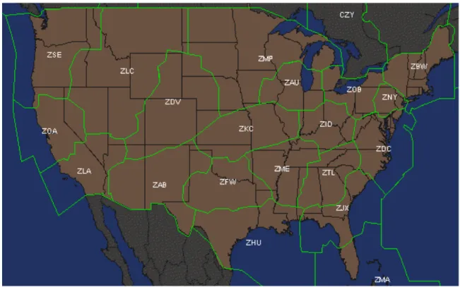
The highest level of decomposition within the US NAS is the Air Route Traffic Control Center (ARTCC). The FAA has divided the NAS into 22 ARTCCs, with the 20 ARTCCs of the Continental US (CONUS) shown in Figure 2-2. The basic function of the ARTCC is to separate aircraft traveling between airports, or while enroute (Nolan, 2010). However, controllers in an ARTCC also provide services for aircraft climbing to and descending from their cruising altitude. In remote areas, they may provide approach and departure services to small tower-controlled or untower-controlled airports.
Figure 2-2. NAS ARTCC facilities (VATSIM Cleveland ARTCC, 2017).
If the FAA determines that safety and efficiency would be increased if a smaller facility were responsible for a given piece of airspace, an ARTCC may delegate aircraft separation responsibility to that facility.
For airspace surrounding many major airports, radar services may be available for departing and arriving aircraft and the FAA facility is referred to as a Terminal Radar Approach Control (TRACON) or Radar Approach Control (RAPCON) for a military facility. The basic function of the TRACON or RAPCON is to provide separation for aircraft through the sequencing and merging of arriving traffic to an airport or the managing of departing aircraft while climbing to their enroute cruise altitude. A depiction of CONUS terminal airspace is shown in Figure 2-3.
Figure 2-3. NAS TRACON and RAPCON facilities (North America Region Training Academy, 2017).
For airspace in the immediate vicinity of an airport, the FAA facility is referred to as an ATC Tower (ATCT) whose primary responsibility is to ensure sufficient runway separation between aircraft landing and departing (Nolan, 2010). In the US, many smaller airports are non-towered and uncontrolled, and no ATC services are provided but pilots communicate on a Common Traffic Advisory Frequency (CTAF).
A typical flight profile of an aircraft flying from one airport to another is generically shown in Figure 2-4. For example, an aircraft could takeoff from an airport in Class B airspace while communicating with an ATCT, then transfers communication to a TRACON facility during its climb to cruising altitude. Prior to reaching cruise altitude, the aircraft may be handed off to an ARTCC for communication enroute in Class A airspace. When nearing its destination, the aircraft may descend into Class E airspace and transfer communication to another TRACON facility. Finally, the aircraft may enter Class C airspace nearing the airport, and after transitioning to final approach be switched to ATCT for landing.
Figure 2-4. Typical flight profile (Aviation Stack Exchange, 2017).
2.2.2 Air Traffic Controller Division of Labor
Due to the vast size of an ARTCC, these areas are divided into sectors. Sectors have lateral and vertical boundaries which vary in shape, size, and altitude (Histon, 2008). Depending on the size, complexity, or congestion of a sector, it may have a single controller or a team of controllers to manage aircraft within it. The controller directly communicating with the aircraft is the radar controller, responsible for issuing altitude, heading, or airspeed changes to ensure separation between participating aircraft. The sector may also be staffed with a radar
associate/nonradar controller whose duties are to assist the radar controller when separating
aircraft that do not appear on the radar display and updating the Flight Progress Strips (FPS) to accurately reflect aircraft position, altitude, and route of flight (Nolan, 2010). A sector may include a flight data controller, who assists in coordination between controllers and other agencies.
Inside TRACON and RAPCON facilities, the primary division of labor is similar to controllers in ARTCCs. Approach control and departure control positions are usually designated and could vary in number from a single controller to forty controllers depending upon congestion within the airspace (Nolan, 2010). Similar to ARTCCs, TRACON and RAPCON facilities are similarly equipped with radar to provide separation services for participating aircraft.
Inside ATCT facilities, the division of labor is different from ARTCC or TRACON facilities. The local controller is primarily responsible for aircraft separation within the airport traffic area and taking off or landing on the airport’s active runways (Nolan, 2010). At busy airports, this position may be separated into two or three controllers, each tasked with controlling different runways for takeoff or landing. For ground operations not on active runways, a ground
controller is responsible for aircraft separation and taxiing vehicles (Nolan, 2010), which also
may be separated at busy airports. In addition, other controllers may be assisting, supervising, or managing controllers or coordinating within and between facilities.
2.2.3 Air Traffic Control Tasks
To provide the services required controllers must perform a number of tasks during routine operations. As an example, a cognitive task analysis of a radar enroute controller (ARTCC controller) determined the controller’s primary tasks to be the following (Seamster,
Redding, Cannon, Ryder, & Purcell, 1993):
• Maintain situation awareness
• Develop and revise sector control plan • Resolve aircraft conflict
• Reroute aircraft • Manage arrivals • Manage departures • Manage overflights • Receive handoff • Receive pointout • Initiate handoff • Initiate pointout • Issue advisory • Issue safety alert
This research focuses on a subset of the first task, “maintain situation awareness,” which corresponds to controller state awareness. However, this task is often a prerequisite to other tasks on the list. Conversely, the other tasks controllers perform may provide insight into their state awareness.
While TRACON controllers specialize in sequencing aircraft into the airport from the enroute environment or transitioning aircraft from the airport to the enroute environment, their tasks are largely the same as ARTCC controllers’ tasks. However, control within the ATCT differs considerably from the radar environment. According to Nolan, local controllers (Nolan, 2010):
• Determine the active runway
• Issue landing and takeoff clearances • Issue landing information
• Sequence landing aircraft
• Coordinate with other controllers
• Issue weather and Notices To Airmen (NOTAM) information to pilots
• Operate the runway and approach lighting system
In addition, tower control primarily involves sequencing aircraft rather than providing separation, the latter is usually accomplished by pilots. However, state awareness requirements exist for all controllers depending on their current task. They receive much of their state awareness by inputs from the system, particularly at their control stations.
2.2.4 Air Traffic Control Stations and Structure
Controllers receive various inputs to accomplish their tasks. While tower controllers are able to perceive the system directly (looking out of the tower cab window), TRACON and ARTCC controllers must rely on a system of sensors, displays, and other controllers to perceive
required information for task accomplishment. Under radar control, controllers provide separation services primarily using a Traffic Situation Display (TSD), which displays primary or secondary radar returns to a display screen. Non-radar controllers must use other means to gain aircraft position awareness for separation. Although all controllers utilize FPS, these prove invaluable for non-radar controllers to maintain awareness and provide separation. FPS are standardized strips of paper (electronic versions exists) displaying aircraft clearance, but which controllers mark to provide a visual representation of the most current clearance or other notes.
When ATC services are used, the primary medium for coordination between pilots and controllers is verbal communication. This communication has traditionally been conducted using radio communications with each controller assigned one or more frequencies to communicate with aircraft within their area of responsibility. Controllers have access to telephones to coordinate with other controllers within and between facilities. To ensure accurate understanding and brevity, communications procedures are rigidly structured. To reduce communication congestion and misunderstanding the use of Controller-Pilot Data Link Communications (CPDLC), a means of non-verbal communication between pilots and controllers, is being expanded into the tower and enroute environment (Federal Aviation Administration, 2017). In addition to structured communications, both the NAS and ATC system are characterized by structured procedures. Navigation and separation in the NAS are dependent upon pilots and controllers abiding by specified procedures during all phases of flight. During VFR operations, procedures for altitude during cruise flight, pattern procedures within the vicinity of airports, and right-of-way rules have been established. During IFR operations, procedures are more restrictive, with aircraft following specific ground-based or satellite-based navigational routes, controller instructions and clearances, and coordinated plans during normal and contingency operations. This allows for the controllers to better project future aircraft position and crew actions to accomplish their purpose, maintaining NAS safety.
2.3
U
NMANNED
A
IRCRAFT
S
YSTEMS
B
ACKGROUND
An unmanned aircraft is simply an aircraft with its aircrew removed from the onboard cockpit and replaced by a computer system and radio-link. More formally, the FAA has defined UAS as “an unmanned aircraft and its associated elements related to safe operations, which may include control stations (ground, ship, or air-based), control links, support equipment, payloads, flight termination systems, and launch/recovery equipment” (Federal Aviation Administration,
2013). For the purposes of this research, an UAS will be decomposed into the following distinct elements.
2.3.1 Unmanned Aircraft System Elements
An UAS consists of five distinct elements as follows: An Unmanned Aircraft (UA), Control Station (CS), UAS Operator (UASO), control link, and communication link. A visual representation of the elements can be seen in Figure 2-5.
Figure 2-5. UAS architectural elements.
The UA element is a device used or intended to be used for flight in the air that has no onboard pilot (Federal Aviation Administration, 2013), analogous to a Manned Aircraft (MA) with respect to the numerous systems (e.g. flight controls, navigation, etc.) required to operate in the NAS. The CS is the equipment necessary to operate an UA (Federal Aviation Administration, 2013), analogous to a cockpit in a MA. The UASO operates the UA from inside the CS and is the pilot in command charged with the safe conduct of a flight (ICAO, 2011), analogous to a pilot. Unlike MA, the UASO requires a wireless link to manage the UA. The control links are the data links between the UA and CS for the purposes of managing the flight (ICAO, 2011), which can be decomposed into a telecommand link (up-link) and telemetry link (down-link) as shown in the blue and purple dashed lines of Figure 2-5. The telecommand link sends control commands from the CS to the UA and the telemetry link sends feedback from the UA to the CS. Depending on UAS type, the control links may operate within Line Of Sight (LOS) or Beyond Line Of Sight (BLOS). BLOS control links must pass through an intermediary before reaching a
node within LOS of the UA, typically a satellite but can be linked ground nodes. The communication link is the voice or data relay of instructions or information between the UASO and the controller or other NAS users (Federal Aviation Administration, 2013), similar to MA. Communication links may operate in different ways, as shown in green dotted and black solid lines in Figure 2-5. If the CS is close to the ATC facility controlling the UA, then communications may go direct between the CS and ATC facility, bypassing the UA. Or, the communication link may pass through the UA, either LOS or BLOS. Finally, the communication link may pass through a terrestrial line from the CS to the ATC facility.
2.3.2 Unmanned Aircraft System Categorization
UAS are a broad category and usually decomposed by the capability or size of the aircraft, yet the boundaries between categories are often blurred. The Department of Defense (DoD) categorization is shown in Figure 2-6 (Department of Defense, 2011).
Figure 2-6. DoD UAS group descriptions (Department of Defense, 2011).
The FAA has categorized small UAS operations under Part 107 of the CFR (Code of Federal Regulations, 2017), where the UA must weigh less than 55 pounds and flown within Visual Line-Of-Sight (VLOS) below 400 feet AGL. The FAA and National Aeronautics and Space Administration (NASA) are researching low altitude airspace allocation to UAS via UTM (UAS Traffic Management) (NASA, 2015). However, this research is scoped to UAS integrated within controlled airspace and managed by controllers similarly to MA, typically Group 3 to 5 in Figure 2-6 whose characteristics are described next.
2.3.3 Unmanned Aircraft System Characteristics
The primary characteristic differentiating UAS from MA is the location of the operator, which changes the system in many ways. If the system desires operator input during flight, a wireless link is required between the UASO and the UA for aircraft control. With this architecture, UAS control links are likely more vulnerable than their manned counterparts (Lacher, et al., 2010; US Department of Transportation, 2014). Lost and faded links can be caused by a number of issues, such as equipment failure (Austin, 2010; Neale & Colin, 2015), human error (Neale & Colin, 2015), Radio Frequency (RF) multi-path (Neale & Colin, 2015), weather interference (Petranovich, 2016; VantagePoint, 2016), terrestrial blockage (Austin, 2010; VantagePoint, 2016), pilot maneuvering, and airframe blanking. If the duration of the control link loss exceeds established requirements, a lost link has occurred. Lost Link (LL) is defined as an interruption or loss of the control link, or when the pilot is unable to effect control of the aircraft (FAA, 2012). To mitigate the consequences when a LL occurs, UA are normally designed to execute an automated LL procedure to either attempt to re-establish the control link connectivity or otherwise safely conclude the UA flight.
The lack of an onboard pilot combined with the design of automated LL procedures highlights the opportunity for different control architectures and automation available for UA. For example, while UAS operations currently include an operator with the ability to maneuver the aircraft real-time (FAA, 2012; Federal Aviation Administration, 2013), the technology is available for changing the current paradigm of the ratio of pilots to aircraft, which is currently at least one pilot for every one aircraft. Fully autonomous operations, zero pilots to one aircraft, or multi-vehicle control, one pilot to many aircraft, are potential control architectures (Cummings, 2004).
Another significant change among UA is the difference in sensory cues available to the operator. The UASO cannot directly perceive the aircraft or environment, which changes the system in a variety of ways. Without fully autonomous operations, the operator must rely on a telemetry link with displays for aircraft control as described above. In addition, the operator can no longer accept visual clearances from the controller, either visual approach or visual separation clearances. Currently, federal regulations state that “vigilance shall be maintained by each person operating an aircraft so as to see and avoid other aircraft” (Code of Federal Regulations, 2016) and “no person may operate an aircraft so close to another aircraft as to create a collision hazard”
(Code of Federal Regulations, 2016). Yet UASO cannot fulfill the see-and-avoid regulatory requirements using traditional methods, namely the pilot’s vision. UAS must ensure they remain ‘well clear’ of not only airborne traffic, but also ground obstacles and weather hazards. This may require technology to provide a means for ‘self-separation’ and collision avoidance (FAA, 2012).
Self-separation is analogous to the requirements for manned aircraft to remain well clear of other
aircraft. In addition, collision avoidance technology may be required to provide similar performance as currently fielded Airborne Collision Avoidance Systems (ACAS) on manned aircraft, such as TCAS (Traffic Collision Avoidance System).
2.3.4 Unmanned Aircraft System Integration Challenges from Literature
Prior work on UAS-integration in the NAS has revealed multiple challenges based in part on characteristics described above. Although a LL procedure is a mitigation of wireless control link vulnerability to disruption or loss, many federal agencies and researchers have shown human-system integration concerns with UAS contingency procedures. These concerns include delayed controller notification of a LL state (FAA, 2012), consistent and predictable UA responses following LL (FAA, 2012; Federal Aviation Administration, 2013; Comstock Jr., McAdaragh, Ghatas, Burdette, & Trujillo, 2014; Yuan & Histon, 2014), and integration of LL procedures in ATC automation systems (FAA, 2012).
Using surveys of controllers, manned aircraft pilots, and UASOs, Yuan and Histon determined information required for each agent to safely integrate UAS in the NAS (Yuan & Histon, 2014). Among their many findings they described the variety of control architectures that could lead to different behaviors of different UAS types. Some could behave similarly to manned aircraft, while others may need to be treated similarly to birds, weather, or other non-controllable objects. Indeed, differences in the control architecture from fully autonomous aircraft to UASOs controlling multiple UAS may exacerbate the non-controllability of UAS in the future (Yuan & Histon, 2014).
In addition to control architectures, Yuan and Histon found controllers’ most often cited new information requirement was UAS Sense-And-Avoid (SAA) capability.5 Also using surveys of controllers, Comstock et al. (2014) found that controllers require whether an aircraft is manned or unmanned through symbology or data-tag information for multiple reasons. One
5 Sense-And-Avoid (SAA) is a function to act in the place of a human pilot to detect and resolve certain hazards to
reason is their inability to see-and-avoid, information a controller needs to make decisions regarding traffic calls, separation, and sequencing (Comstock Jr., McAdaragh, Ghatas, Burdette, & Trujillo, 2014). The FAA cited ATC challenges to include see-and-avoid responsibilities in their integration roadmap (Federal Aviation Administration, 2013), while the FAA’s Concept of Operations (CONOPS) for UAS suggests technology-based separation such as delegated separation (FAA, 2012), similar to the Next Generation Air Transportation System (NextGen) concept of Equivalent Visual Operations (EVO), where aircraft self-separate using technology such as Automatic Dependent Surveillance-Broadcast (ADS-B) instead of vision (Simons, DeSenti, Estes, & Hawkins, 2005; Domino, Tuomey, Mundra, & Smith, 2010; Domino, Tuomey, Mundra, Smith, & Stassen, 2011; Prinzel III, et al., 2011; Kenny, 2013), as a possible mitigation to see-and-avoid concerns.
Due to design considerations such as mission goals and development factors, UA have proven vulnerable to inclement weather thus far in their use (Rabe, Abel, & Hansman, 2016). As of 2013 the largest issue with UAS in the DoD remained the inability to operate in bad weather (Department of Defense, 2013). A Government Accounting Office (GAO) report stated UAS are more likely to be grounded in inclement weather than manned aircraft (GAO, 2005), specifically regarding wake vortex and other turbulence along with airframe icing. This weather susceptibility may be due to their lighter weight structures, small airframes, and high-aspect ratio wings (Rabe, Abel, & Hansman, 2016). The FAA highlighted unmanned aircraft’s susceptibility to wake vortex and other turbulence due to their unique characteristics (Federal Aviation Administration, 2013). Many UA are designed to maintain a steady flight path for their payload sensors, using large aerodynamic surface areas and high aspect ratio wings to do so (Austin, 2010). However, this increases the response when turbulence is encountered. In addition to turbulence, airframe icing poses a challenge for UAS operations. Ice accumulation on UA is a common problem (Nelson, 2017), causing a number of accidents (GAO, 2005). Turbulence, airframe icing, and high winds are less detectable by the UASO due to their lack of sensory cues (Rabe, Abel, & Hansman, 2016). In addition, the possibility of LL increases the risk because the