HAL Id: hal-02153546
https://hal.archives-ouvertes.fr/hal-02153546
Submitted on 12 Jun 2019
HAL is a multi-disciplinary open access
archive for the deposit and dissemination of
sci-entific research documents, whether they are
pub-lished or not. The documents may come from
teaching and research institutions in France or
abroad, or from public or private research centers.
L’archive ouverte pluridisciplinaire HAL, est
destinée au dépôt et à la diffusion de documents
scientifiques de niveau recherche, publiés ou non,
émanant des établissements d’enseignement et de
recherche français ou étrangers, des laboratoires
publics ou privés.
Approach of the Prediction of the Thermal Field within
an element during the machining operations
Zuhaitz Areitio, Guillaume Cohen, Jean-Michel Baleynaud, Stéphane
Segonds, Pierre Lagarrigue
To cite this version:
Zuhaitz Areitio, Guillaume Cohen, Jean-Michel Baleynaud, Stéphane Segonds, Pierre Lagarrigue.
Approach of the Prediction of the Thermal Field within an element during the machining operations.
High Speed Machining, Sitxt International Conference. 21-22 March 2007, San Sebastián (Spain),
Mar 2007, San Sebastián, Spain. �hal-02153546�
Approach of the Prediction of the Thermal Field within an Element
during the Machining Operations
Z. Areitio1, G. Cohen1, JM. Baleynaud1, S. Segonds1, P. Lagarrigue2 1LGMT, UPS Toulouse 3, France
2LGMT, CUFR J.F.Champollion, Albi, France
Abstract
During an operation of manufacture per removal of chip, the phenomenon of cut induces thermal stresses altogether by self-heating within work material and frictions with the interface tool/element. In conventional machining, calorific energy is evacuated in the chips but also in the work material and the tool. This thermal rise in the part can lead to dilations at the origin of errors of machining and local heat treatments. The goal of this work is to set up a prediction model of the thermal field in the work material during machining. This work is carried out in the case of drilling. In a first part, several methods of calculation are used to quantify the temperature field. In a second part, the measurements taken in infra-red thermography make it possible to compare the results theoretic and the experimental values. Finally, a calorimetric approach is proposed.
Keywords:
Machining, Thermal Field, Element, Prediction, Infrared, Calorimetry
1 INTRODUCTION
During machining, the cut is performed by penetration of the edge of the tool inside the object. The energy delivered by the machine to the tool is distributed under several forms to the tool, the piece and the environment. The process is complicated and justifies a lot of research works.
Definitely the thermal aspect is important because of side-effects induced, such as dimension variations, which may be responsible of a decay of machining accuracy. The application chosen is drilling operation.
Our goal is to set up a prediction method based on the knowledge of the thermal field in the object. Although most of thermal energy is evacuated by chips, the heat generated in the work material keeps noticeable and we try to value it.
In this paper, we will shortly review the drilling phenomenon; then we propose the simulation approach, then experimental one; we will conclude by the comparison of results and planned operations.
2 HEAT GENERATION DURING MACHINING 2.1 Historical elements
The thermal side-effects of machining have been studied for ages due to their consequences on the machining allowance. For example, for which concerned our study: Blok [1], Rapier [2], Trigger and Chao [3,4] and Lowen [5]. The complexity of heat transfers, subdued to the variety of materials, shapes and environments involved justifies a large amount of research works.
Most of studies we could find in the bibliography are treating the problem of orthogonal machining, there the problem of shapes is significantly simplified and the application problems are generally more critical.
As shown on figure 1, the cut phenomenon results in the creation of three shearing zones, each contributing to the energy machining need together under mechanical and thermal forms. The chip evacuates a large part of this energy from both zones 1 and 2, while the tool carries a part coming from zones 2 and 3; the rest, resulting into heat, increases the piece temperature.
Figure 1: Thermal zones: 1 Primary zone of shearing; 2 Secondary zone of
shearing; 3 Zone of skin.
Blok [1] developed analytical methods for valuing the superficial temperature of a piece submitted to a concentrated heat source.
The application on machining was started by Trigger and Chao [2] with the evaluation of chip temperature, assuming it carries 90% of the heat. Lowen considered the sliding of the tool on the piece and quantified the
temperature of the shearing plan. Which later lead to an analytical expression of the heat to be dissipated in the piece, still in use for orthogonal cutting.
2.2 Short view of the state of the art
More recently the works of Komanduri [6] summarized the history of the art and assumed an image heat source supplementing the primary shear plane heat source which positioning lead to the determination of tool and work material temperatures
The authors compared analytical and numerical methods, such as Tieu [7] proving fair accordance. The solution allows the valuing of either tool and interface tool-work material, taking in account the friction.
Beside simulation studies, experimental works were developed. Kwon [8] used infrared thermography as an approach of the interface tool-chip. And Quan [9] made a calorimetric study of the cutting heat.
2.3 Purpose of the study
Our team is working on turning, too, but besides, we have recently chosen to study the drilling because of several reasons listed below.
Although machining planning and cooling strategies may limit the consequences of the piece local overheating, it slows machining and it would be of some interest to be able to predict in order to optimize.
For experimental purpose, geometries involved in drilling allow the use of special sensors such as infrared and temperature sensors in a more easy way than for other machining operations. In this case, the drilling contributes to supplement the knowledge of the phenomenon.
3 DRILLING MODELLING 3.1 Introduction
Our laboratory started some times ago a study of thermal aspects of machining and their consequences on the piece itself. First developments were and are still held on orthogonal turning. This process was first investigated there it appears some more simple to model and simulate. Besides, the drilling operation is some more complicated there it involves random parameters such as chip development and position in the machining field. On the other hand this configuration provides some advantages for experimentations. For example it is rather easy to perform infrared measurements for we can get rid of obstacles and ensure a satisfactory insulation from artefacts with simple radioactive protections. Another advantage of the drilling configuration is to open way for an experimental calorimetric study, as the process allows a very limited intrusion in the calorimeter (the drill) which thermal losses may be controlled. For these reasons, the laboratory decided to open a new investigation campaign in order to complete the study of the subject.
Although few evocated in the bibliographic review, the numerical simulation attempts are numerous (for example El Hossaini [10]). But few are devoted to the drilling process.
From a thermal point of view, the phenomenon recalls the classical problem of thermal shock on surface of semi-infinite body, under one-dimensional flux, which solution is analytically represented by the erf error function.
In fact, it is some more complicated, because it is clearly a two dimension problem, even if the hole cylindrical surface could be supposed as adiabatic. The experimental results shown below will confirm the reality of a radial heat transfer.
We did not try to implement analytical solutions, because of the complexity of the geometry. As a matter of fact,
compared to the orthogonal cutting, drilling adds several levels of modelling.
For mechanical aspect, as regards to the turning tool, the drill induces much more friction. Although by converting the trajectory, it could be assumed an analogy between the sharp end of the drill and the turning tool, the helical side has noticeable effects to be taken in account. The cylindrical interaction might be compared to a turning process with no pressure effect but the one induced by the extracted chip. In such a case one more dimension is added to the problem.
From an energetic point of view, the problem is clearly three-dimensioned and we may point two difficulties: a depth evolutionary heat generation which concentration increases during machining, and an irregular extraction of heat by the chip flow.
It then appears more easy to use numerical methods, in evolutionary state, in order to simulate the work material behaviour.
The first finite difference model implemented for metal cutting was realized thanks to Rapier [1] in 1954.
3.2 Finite volumes scheme: first step
Description
This solution has significant interests. Mainly, it allows an easy explicit description of the phenomenon and it is stable and converging.
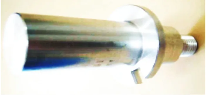
The basic reference geometry is the shape of the test part used un either calorimetric and infrared experimentation described below (Figure 2). The cylinder is axially machined during experimentation, from an end.
The cylinder gets divided into cylindrical elements along axis and radius. Axial division defines drilling time-space step.
Elements are of several kinds and have different properties.
External superficial elements are not constrained and exchange energy with the environment by convection and radiation and by conduction between them and with inner elements. It should be noted that the edge elements are particular.
Figure 2: Calorimetric test piece.
Inner conservative metal elements are exchanging heat by conduction (still a difference for edge element which exchanges by convection and radiation too).
Inner machined elements have exchange alterations concerning areas and heat transfer modes due to the positioning of the drill according to time (i.e. The equation contains modes description and a selection parameter used as area parameter too.
The cutting energy is considered as an input of the model and the basis for predicting the thermal field.
The first step includes limitations: the drilled cylinder is supposed adiabatic (limit 1) and the chip extraction isn't simulated, such as subdued exchanged energy (limit 2); the extraction of the drill isn't programmed (limit 3).
The implementation was realized in visual basic for commodity of testing.
Only the drilling phase was modelled, yet. Due to the emergency the stop and retract of the drill wasn't implemented. So results should be compared to experimental ones on the 5-6 first machining seconds.
Figure 3: Partial thermal simulation of heat increase on test piece surface during drilling, using finite volumes. The observation of the figure 3 shows a continuous increase of temperature.
The phenomenon of constant increase is caused by the limit 2 of the model. The heat extraction isn't sufficient and heat keeps concentrated in the hole. Besides, we could verify that the values predicted were in the same order as in experiments.
Next step is to include chip flux in the model and drill extraction.
3.3 Finite elements scheme
We have tested the SAMCEF software which provides a description language for defining geometry, materials, mesh and boundary and time conditions.
The difficulty consists in the modelling of the machining induced heat flux and the evacuation with the chips. This task is still in progress and it is too early to display results.
3.4 Conclusion on simulation
We encountered various difficulties for the description of energies involved in the case of drilling.
Finite volumes provide encouraging results.
Concerning finite elements, the use of a software taking in account thermal constrains would certainly be appropriate.
4 EXPERIMENTALS 4.1 Infrared Thermography
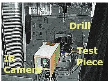
During the drilling operation, we have positioned an infrared camera, protected from chip impacts an parasite radiations. The sensor was pointing the test element, previously black coated. The sensor is protected from impacts by a quartz lens, for drilling implies unpredictable chip dispersion and a real risk for the camera main lens and at least its coating. Besides, the camera is protected by an insulating reflective coating in order to protect it from any damage and to prevent it from creating measure parasites due to its intrusion inside drilling process. We used a Thermovision A40-M constructed by FLIR. The positioning is situated by figure 4. During machining, the machine door is close and covered with neutral material.
In this configuration, the camera provides thermal scenes and records the thermal evolution during drilling. As an illustration, we have selected some pictures as typical of scenes we could observe during test operations. These images are displayed below and shortly commented.
Figure 4: Thermal evolutions of points of the outer surface of the cylindrical test piece (diameter 14 mm) during drilling (Point 1 is at top of piece, point 5 is lower
than drilling end).
Figure 5: Beginning of drilling; test 18mm. In figure 5 drilling just started and a chip is regularly rolled, develops around the drill and turns with it. It can be remarked that the highest temperatures can be observed on the drill itself and the chip, which heat extracting role is known for ages. The thermal flux deeps slower than the drill due to piece inertia.
Figure 6: During drilling; test 18mm.
Spots were surveyed during operation (points 1 to 5), situated on the vertical distributed on a length greater than drilling. These points relate to those which behaviour is simulated in the numerical approach.
It can be remarked on figure 6 that chip has got broken into smaller pieces which are randomly distributed in the environment and at higher temperature (scale expands during operation) than regular chip, suggesting the stronger constraints that produced it.
Compared thermal behaviour of superficial points during drilling for different tests cylinders
The following figures display the propagation of the heat flux inside the work material. In this, the phenomenon recalls the thermal shock at top of a cylinder (in its increasing temperature part). In fact, as expressed above, this similarity has its limits.
The results were obtained from test aluminium cylinders of several radius and with one drill of diameter 13mm.
Figure 7: Thermal evolutions of points of the outer surface of the cylindrical test piece (diameter 14 mm) during drilling (Point 1 is at top of piece, point 5 is lower
than drilling end).
Figure 8: Thermal evolutions of points of the outer surface of the cylindrical test (diameter 15mm). The camera allows recording of the thermal scene: in extents, it stores images which can be treated in line, or post-treated.
Hence, it can display and store thermal movies, static scenes and the thermal evolution of points according to the time operation.
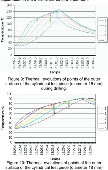
Figures 7 to 10 show the time depending evolution of temperatures at points situated on the surface of the cylinder. The tested element is made of aluminium, drilled with axial speed of 4 mm/s.
As could be expected, we can remark that the maximum of temperature observed is lower and longer to be reached in cases when diameter increases. This can be explained by diameter difference of test cylinders. Concerning the maximum value, both mass and material remaining thickness can justify the decay in case or
increase of the element diameter. The lateness finds its explanation in the thermal inertia of the element.
Figure 9: Thermal evolutions of points of the outer surface of the cylindrical test piece (diameter 16 mm)
during drilling.
Figure 10: Thermal evolutions of points of the outer surface of the cylindrical test piece (diameter 18 mm)
during drilling.
The sudden 20K decay occurring at random periods is certainly an artefact, probably caused by the shading of the measured point by a chip.
Which is more surprising is that the curves of temperature increase appear to cross in figure 6. This phenomenon occurs in no other figure, which tends to indicate an artefact.
An explanation is brought by the consideration that it only concerns the curve number 1: which is the closer to the drilling starting. This seems to indicate an error o focusing the very suited point.
Figure 11: Thermal evolutions of points of the outer surface of the cylindrical test piece (diameter 20 mm)
during drilling.
Besides, if this explanation is correct, which is probably the case, the measured temperature is the one of the drill,
close to the work material. In such a case, we reach another information. Anyway, the dynamic of the sensor is not sufficient to credit any value to the accuracy of a measure performed on an complex shape at fast motion. Still comparing these figures, we can observe that the phasing of curves increases with the diameter of the tested element. This phenomenon can be explained by the fact that the camera measures only a superficial temperature.
Hence, the thickness increasing causes the development of test inertia which, on one side, slows the heat transfer and, on the other side, increases the distance from heat flux origin to its observation.
We can also consider the diffusion speed of the heat flux in the work material and compare it with the machining speed. This study will be made using tests made of various materials.
Compared thermal behaviour of point 2 during drilling for different tests cylinders (fig.12)
Figure 12: Thermal evolutions of hotter points of the outer surface of the cylindrical test piece.
It could be established that in any case, the point reaching the highest temperature is point 2, that is to says the second point of the outer cylinder from the beginning side of drilling. This result is not surprising as point 1 (upper point) is closer of wider heat exchange surfaces which have a cooling effect for the zone.
Figure 8 compares time evolution of point 2 for the different tests. They are similar except for case of test diameter 15mm which happens to have a singular behaviour, still not properly explained.
4.2 Calorimetry test bench
Another problem is to value the transformation of the energy during drilling. Considering the mechanical energy provided by the machine-tool results in mechanical cutting mechanical transport of chips, heating of tool and elements: together work material, chips and environment. Two approaches can be carried out: static and dynamic, in order to value each quantity.
These considerations have lead us to prepare a calorimetric test bench, to be installed on the machine-tool. It is prepared to be held on machine plate via an effort sensor device able to measure torques and forces involved during drilling.
Figure 13 shows the calorimeter in which a dedicated disposal holds the test cylinder.
Thermocouples are stuck at chosen points, linked to a scanner-voltmeter HP3497a, controlled via an IEEE interface by a computer.
The system is completed by a water circulation regulated in temperature.
The static experiment has for object to establish an energetic balance of the drilling operation.
Figure 13: Calorimetric test bench.
The dynamic approach will deal with powers and should provide more direct usable results although it will be more difficult to extract accurate data.
5 CONCLUSION
We have presented a developing research program. The knowledge of energetic transformations during machining is a step to an optimization of machining processes. The study of former works brought a lot of understanding elements, though a lot is still to be carried on, because the problem is really complex, due to the huge number of parameters involved in phenomena.
Theoretical models have been prepared, using numerical methods, for the analytical solution still seems difficult to establish. Preliminary results were obtained, still needing improvements.
An experimental approach of the drilling was presented, which soon provided interesting elements through infrared investigation. A calorimetric study is being developed in order to supplement the study of the thermal field inside the work material, which corresponds to our main target. We hope to contribute in the optimizing of machining for allowance reduction, operating speed, machines liability and maybe even, energy saving.
6 SUMMARY
This paper summarized the works carried out by LGMT drilling team in 2006. The investigation of the heat field in the work material goes on.
7 ACKNOWLEDGMENTS
We extend our sincere thanks to all who contributed to help in the development of this study.
8 REFERENCES
[1] Blok H., 1938, Theoretical study of temperature rise at surfaces of actual contact on under oiliness lubricating conditions, Proceedings of General discussion on Lubrication and Lubricants, Institute of Mechanical Engineers London: 222-235.
[2] Rapier AC, 1954, A theoretical investigation of the temperature distribution in the metal cutting process, Br. J. Appl. Phys. 5 (11): 400-405.
[3] Trigger KJ, Chao BT. 1951, An analytical evaluation of metal cutting temperature. Transactions of ASME 73: 57-68.
[4] Chao BT, Trigger KJ., 1953, The significance of thermal number in the metal machining. Transactions of ASME 75: 109-20.
[5] Lowen EG, Shaw MC., 1951, On the analysis of cutting tool temperatures. Transactions of ASME 73: 57-69.
[6] Komanduri R et Hou ZB, 1999, Thermal modelling of the metal cutting process Part I. International journal of Mechanical Sciences 42 (2000): 1715-1718. [7] Tieu K, Fang XD, Zhang D, 1998, Finite elements
analysis of cutting tool temperature field with adhering layer formation, Wear 214 (20): 252-258. [8] Kwon, Schiemann et Kountanya, 2000,. An inverse
estimation scheme to measure steady-state tool-chip
interface temperatures using an infrared camera. International Journal of Machine Tools & Manufacture 41 (2001): 1015-1030.
[9] Quan Yan Ming, He Zheng Wei, Dou Yong, 2006, Study on Cutting Heat in High Speed Machining Basing on Calorimetric Method. Fifth international conference on High Speed Machining, March 14-16. [10] El Hossaini TM, El Shazly MH, Abd Rabu M, 2001,
Finite element simulation of metal cutting considering chip behaviour and temperature distribution, Mater. Manuf. Process 16 (6): 803-814