Publisher’s version / Version de l'éditeur:
Construction Technology Update, 1998-07
READ THESE TERMS AND CONDITIONS CAREFULLY BEFORE USING THIS WEBSITE.
https://nrc-publications.canada.ca/eng/copyright
Vous avez des questions? Nous pouvons vous aider. Pour communiquer directement avec un auteur, consultez la première page de la revue dans laquelle son article a été publié afin de trouver ses coordonnées. Si vous n’arrivez pas à les repérer, communiquez avec nous à [email protected].
Questions? Contact the NRC Publications Archive team at
[email protected]. If you wish to email the authors directly, please see the first page of the publication for their contact information.
NRC Publications Archive
Archives des publications du CNRC
Access and use of this website and the material on it are subject to the Terms and Conditions set forth at
Pressure equalization in rainscreen wall systems
Rousseau, M. Z.; Poirier, G. F.; Brown, W. C.
https://publications-cnrc.canada.ca/fra/droits
L’accès à ce site Web et l’utilisation de son contenu sont assujettis aux conditions présentées dans le site LISEZ CES CONDITIONS ATTENTIVEMENT AVANT D’UTILISER CE SITE WEB.
NRC Publications Record / Notice d'Archives des publications de CNRC:
https://nrc-publications.canada.ca/eng/view/object/?id=dfd381a2-df13-4f88-8ee8-7d0773756a36 https://publications-cnrc.canada.ca/fra/voir/objet/?id=dfd381a2-df13-4f88-8ee8-7d0773756a36b y M.Z . Rousse a u, G.F. Poirie r a nd W.C. Brow n
A pressure-equalized rainscreen (PER) wall is a multiple-line-of-defence approach
to rain penetration control. This Update defines pressure equalization and
discusses the various elements that must be incorporated in a PER w all to
minimize rain penetration due to air pressure differentials.
C o n s t r u c t i o n T e c h n o l o g y U p d a t e N o . 1 7
Rain can en ter on ly if a com bin ation of th e follow in g th ree con d ition s are p resen t: rain w ater d ep osited on th e w all, h oles an d cracks offerin g w ater leakage p ath s in w ard s an d a force or a com bin ation of forces to d rive w ater in w ard s. Strategies for rain p en etration con trol m u st en tail th e con trol of on e or m ore of th ese con tribu tin g factors.
Variou s ap p roach es to rain p en etration con trol are cu rren tly u sed in th e bu ild in g in d u stry. Th ese ran ge from sin gle-lin e-of-d efen ce assem blies (com m on ly callee-of-d face-seal w alls) to m u ltip le-d efen ce assem blies su ch as th ose th at in corp orate a rain screen , a d rain ed air sp ace an d a w ater-resistan t
m em bran e.1 Th e p ressu reequ alized rain -screen (PER) w all d esign is on e of th ese m u lti-d efen ce ap p roach es. It is based on th e op en rain screen p rin cip le,2 w h ich aim s to con trol all forces th at can d rive w ater in to the wall assembly, i.e., air pressure difference, gravity, su rface ten sion , cap illary action , an d rain d rop m om en tu m . Of th ese forces, air p ressu re d ifferen ce is often a d om in an t on e w ith th e p oten tial to d rive a con sid erable am ou n t of rain w ater in to th e w all assem bly. Th is Up d ate th erefore focu ses on th e con trol of air pressure difference across the rainscreen, and the particular elements of wall assemblies in stru m en tal in obtain in g su ch con trol.
De fining Pre ssure Equa liza t ion
Th e p ressu re equ alization con cep t is sim p le: w h en th e ou tsid e air p ressu re is tran sferred to an air sp ace beh in d th e exterior clad d in g, th e clad d in g is exp osed to a n ear-zero p ressu re d ifferen tial. In practice, the wall assembly m u st com p rise th ree com p on en ts (Figu re 1): a rain screen (i.e., ven ted clad d in g), a com p art-m en ted air ch aart-m ber an d an air barrier system . Th e air ch am ber com -p artm en ts m u st be sm all en ou gh , th e air barrier system m u st be airtigh t
Pressure Equalization in
Rainscreen Wall Systems
2
en ou gh , an d th e area of th e ven tin g th rou gh th e rain screen m u st be large en ou gh to allow su fficien t air to m ove in an d ou t of th e com p artm en ts u n d er th e ap p lied air p ressu re. In a n u tsh ell, th e strategy lies in th e con trol of airflow w ith in an d th rou gh th e w all assem bly.
In th eory, p ressu re equ alization m ean s a zero air pressure differential at all times across th e rain screen , i.e., a com p lete elim in ation of th e d rivin g force for p ressu rin d u ced w ater p en e-tration . In p ractice, h ow ever, p erfect p ressu re equ alization across th e rain -screen at all tim es is n eith er ach ievable n or n ecessary for ad equ ate rain p en e-tration con trol (th e w all assem bly m u st be d esign ed to tolerate th e en try of a sm all am ou n t of w ater w ith ou t d am age).
Prelim in ary stu d ies in d icate th at for p racti-cal p u rp oses, “ad equ ate p ressu re equ aliza-tion ” for rain p en etraaliza-tion con trol m ay be d efin ed as n ot m ore th an 25 Pa p ressu re d ifferen tial across th e rain screen .
Wa ll Com pone nt s for Pre ssure Equa liza t ion
Th e follow in g th ree basic com p on en ts m u st be p resen t in a w all assem bly to m in im ize rain p en etration d u e to air p ressu re d iffer-en tials (Figu re 1):
• an effective air barrier system , • an air ch am ber an d
• a rain screen .
Th ese com p on en ts m u st h ave p rop erly d esign ed featu res su ch as ven t h oles in th e
rain screen an d d elim iters to d ivid e th e air ch am ber in to a series of com p artm en ts.
Recen tly, IRC p erform ed som e exp eri-m en tal laboratory stu d ies to ch aracterize th ese featu res for variou s gen eric w all system s. In a p roject join tly sp on sored by Can ad a Mortgage an d Hou sin g Corp oration (CMHC) an d several w all system m an u fac-tu rers, IRC u sed its u n iqu e d yn am ic w all-testin g facility to stu d y th e relation sh ip betw een th e th ree com p on en ts (listed above) as a fu n ction of th e p h ysical ch arac-teristics of d ifferen t w all assem blies su b-jected to static an d d yn am ic air p ressu res. Sp ecim en s of p recast con crete p an els, brick ven eer/ stu d w all assem blies an d exterior in su lation an d fin ish system s (EIFS) w ere exam in ed for th eir p ressu re-equ alization p erform an ce. Som e w ere also su bjected to rain p en etration tests.
An air barrier system
Th e p erform an ce of th e air barrier system affects th e ability of th e w all assem bly to ach ieve p ressu re equ alization across th e rain screen . Th e air barrier system in p lace w ith in th e w all sign ifican tly red u ces th e flow of air th rou gh th e w all assem bly, an d th erefore greatly con tribu tes tow ard red u cin g th e air p ressu re d ifferen tial across th e rain -screen . Un d er d yn am ic-p ressu re con d ition s, recen t IRC stu d ies in d icate th at excessive flexibility of th e air barrier system w ill resu lt in flu ctu ation s in th e volu m e of th e air ch am ber com p artm en t. Th ese flu ctu ation s ad versely affect th e p oten tial for rap id p res-su re equ alization across th e rain screen . Un d er static-p ressu re con d ition s, th e leakage of th e air barrier system is th e d eterm in in g factor for sizin g th e ven tin g requ irem en ts. Th ese fin d in gs em p h asize th e n eed for an air Dyna m ic a nd st a t ic a ir pre ssure s
on t he ra insc re e n
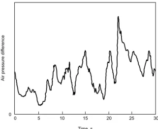
Static (stead y over tim e) air p ressu res on w all assem blies are gen erated by m ech an ical system s an d stack effect w h ile d yn am ic p ressu res (flu ctu atin g qu ickly w ith tim e an d loca-tion ) are cau sed by w in d (Figu re 2). Recen t IRC research in d icates th at d yn am ic as w ell as static air p ressu res m u st be con sid ered w h en ad d ressin g w in d -d riven rain an d th e p ressu re-equ alization p erform an ce of a w all assem bly for rain p en etration con trol.3 Un d er d yn am ic p ressu res, th e
ability of th e assem bly to resp on d qu ick ly to th e ou tsid e flu ctu atin g p ressu re load is critical for ad equ ate p ressu re equ alization ; th is tim e con strain t is n ot an issu e u n d er sta-tic load in g. Th e IRC research sh ow ed th at w all assem blies resp on d d ifferen tly to d yn am ic an d static load in g, resu ltin g in d ifferen t d esign requ irem en ts for th e w all com p on en ts, p articu larly for th e ven tin g of th e rain screen an d th e com -p artm en talization of th e air ch am ber.
Figure 2.Example of wind-induced pressure differential measured across an exterior wall system (Brown et al. Field Testing of pressure-equalized rainscreen walls. ASTM. STP 1034, 1991.)
rigid ity of th eir bou n d aries (i.e., air barrier system , rain screen an d lateral d elim iters) are th e d eterm in in g factors for estim atin g th e ven tin g requ irem en t of th e rain screen . How ever, in w all system s w ith ou t a clear air sp ace, p relim in ary exp erim en tal w ork at IRC su ggests th at th eir p ressu re-equ alization p erform an ce is very sp ecific to th eir p articu lar d esign , an d th at th e d ata available can -n ot be extrap olated to ge-n erate gu id eli-n es.
Th e air ch am ber n eed s to be d ivid ed in to sm aller, sep arate com p artm en ts.2 Rem em ber th at sin ce w in d p ressu re is d yn am ic, th e p ressu re in d u ced on th e bu ild in g façad e varies n ot on ly w ith tim e, bu t also w ith its location on th e façad e. For exam p le, th e air p ressu re in d u ced by w in d can be fairly u n iform n ear th e cen tre of th e w alls, bu t steep grad ien ts (variation s) can d evelop tow ard s th e bu ild in g ed ges an d th e roof lin e.7 Th is sp atial variation in p ressu re can in d u ce lateral airflow w ith in th e ch am ber u n less it is d ivid ed at su itable in tervals. Th e com p artm en tation of th e air ch am ber in to sm aller air com p artm en ts red u ces th e ran ge of w in d -in d u ced p ressu res su stain ed by each of th ese com p artm en ts, resu ltin g in a better p oten tial for p ressu re equ alization across th e rain screen .
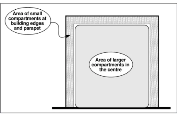
In th e 1960s, Gard en2su ggested th at com p artm en ts be sm aller at location s of large p ressu re variation s (su ch as bu ild in g ed ges an d p arap ets) an d larger in location s of sm aller p ressu re grad ien ts, su ch as in th e cen tral p ortion of th e façad e. Based on th ese p rem ises, Gard en su ggested th at com p artm en t h eigh t sh ou ld n ot exceed 6 m (abou t tw o stories) w h ile com p artm en t w id th cou ld be u p to 6 m in th e cen tral p ortion of th e façad e an d abou t 1.2 m at bu ild in g ed ges an d p arap ets. Recen tly, Can ad ian research in volvin g w in d tu n n el stu d ies8 h as been in itiated for th e d evelop m en t of m ore d efin itive gu id elin es on com p artm en t sizes over th e bu ild in g façad e for PER w all system s. Th ese stu d ies con firm th at Gard en ’s ru le-of-th u m b abou t th e location s on a façad e th at are m ost in n eed of of com p art-m en tation is valid ; th e n eed for sart-m all com p artm en ts at p arap et level is also stressed (Figu re 3).9,10
Th e com p artm en t d elim iters close in th e top , bottom an d sid es of th e com p artm en t. Th ese d elim iters n eed to be som ew h at im p erviou s to air an d p rop erly con n ected to th e rain screen an d to th e p lan e of air-tigh tn ess of th e air barrier system in ord er barrier system w ith in th e bu ild in g en velop e,
as called for in th e 1995 ed ition of th e Nation al Bu ild in g Cod e of Can ad a.4
An effective air barrier system h as low air p erm ean ce, stru ctu ral stren gth , an d con -tin u ity over gap s, join ts an d in terfaces.5 Th e air barrier system m u st be d esign ed to resist air p ressu re in d u ced by m ech an ical ven tilation , stack effect an d w in d w h ile still lim itin g air leakage. Th e system m u st also be rigid en ou gh to su stain th ese air p ressu res w ith a resu ltin g d eflection th at can be accom m od ated w ith in th e w all assem bly. Th ese air p ressu res m u st be tran sferred to th e stru ctu re of th e bu ild in g.
An air chamber
Th e air ch am ber is located betw een th e rain screen an d th e air barrier system . Win d p ressu res in d u ced on th e rain screen are tran sferred to th is sp ace as air is d isp laced betw een th e ou tsid e an d th e ch am ber th rou gh th e ven t h oles located in th e rain -screen . Th e air ch am ber can con sist of a clear air sp ace or oth er ad equ ate op tion s. As an exam p le, in a recen t IRC exp erim en -tal stu d y, on e w all assem bly w ith an air ch am ber m ad e w ith a geosyn th etic d im p led p lastic sh eet w ith a geotextile bon d ed to th e d im p les p rovid ed sim ilar p ressu re equ alization p erform an ce to th at of th e assem bly w ith a clear air sp ace. In som e w all system s, sp ecially d esign ed in su lation m aterials are in ten d ed to p rovid e th e requ ired air ch am ber for p ressu re equ aliza-tion p u rp oses: th e air ch am ber m ay be form ed as a grid of n arrow ch an n els w ith in th e in su lation m aterial, or th e air ch am ber can be h ou sed w ith in th e in su lation m aterial itself w h en its p h ysical p rop erties p rovid e th e requ ired “air p erm eability.” In gen eral, for d yn am ic p ressu re equ alization , th e volu m e of th e air com p artm en ts an d th e
IRC’s Can ad ian Con stru ction Materials Cen tre (CCMC) d evelop ed an evalu ation p rotocol to assess th e “effectiven ess” of air barrier system s.6 It covers requ irem en ts for m axim u m
allow able air leakage rates for air barrier system s for w alls of low -rise bu ild in gs, stru ctu ral air p ressu res (static an d d yn am ic) an d m aterial d u rability. CCMC’s allow able air leakage requ irem en ts for air barrier system s are a fu n ction of th e w ater vap ou r p erm ean ce of th e ou term ost n on -ven ted layer of th e w all assem bly. In an y case, th e m axim u m air leakage rate allow able by CCMC for th e air barrier system in exterior w alls of low -rise bu ild in gs is 0.20 L/ (s·m2) at 75 Pa
to create th e requ ired lateral bou n d ary. In form ation on th e p erform an ce of an y m aterial an d assem bly for th at p u rp ose is scarce at th e m om en t. In p rin cip le, w all com p on en ts in p lace for oth er p u rp oses, su ch as m etal sh elf an gles, can act as d elim iters. Rigid sh eet m etal an d foam p lastic in su lation strip s cou ld likely be u sed as d elim iters, as lon g as th ey can be m ad e relatively airtigh t an d can be in stalled to su stain th e lateral air p ressu re load s.
A rainscreen
A rain screen is th e first lin e of d efen ce again st w in d -d riven rain , an d as su ch is su bjected to all forces lead in g to rain p en e-tration th rou gh its op en in gs an d im p erfec-tion s. Pressu re equ alizaerfec-tion across th e rain screen m in im izes w ater en try in to th e w all d u e to on e force, air p ressu re d ifferen -tial. For p ressu re equ alization to take p lace, th e rain screen m u st be ven ted ; th at is, h oles m u st be p resen t in th e rain screen so th at en ou gh air can be exch an ged
betw een th e ou tsid e an d each com p artm en t of th e air ch am ber. Tw o m ajor issu es arise con cern in g th e ven tin g requ irem en ts: th e am ou n t of ven tin g n eed ed for ad equ ate p ressu re equ alization u n d er static an d d yn am ic p ressu res, an d th e p lacem en t of th e ven tin g for each com p artm en t.
How m uch v e nting
Un d er d yn am ic-p ressu re con d ition s, th e rain screen ven tin g requ irem en ts are m ain ly d riven by th e volu m e of air in th e ch am ber com p artm en t, th e resistan ce to airflow at th e ven t h oles, w ith in th e ch am ber as w ell as betw een th e com p artm en ts, an d th e rigid ity of th e w all assem bly. In d eed , th e larger th e volu m e of air in th e com p artm en t,
th e larger th e volu m e of air th at h as to be d isp laced in an d ou t of th e com p artm en t to obtain ad equ ate p ressu re equ alization across th e rain screen ; h en ce, th e larger th e total area of venting. The more rigid the assembly, th e sm aller th e ven tin g area requ ired . Th e
volu m e/ ven tin g ratio of th e w all assem bly,
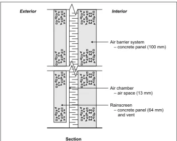
i.e., th e volu m e of th e com p artm en t d ivid ed by the effective cross-sectional area of the vent h oles, is a critical ch aracteristic of th e assem -bly for ach ievin g d yn am ic-p ressu re equ al-ization . Again , IRC’s lim ited exp erim en tal w ork su ggests th at ch am ber com p artm en ts of sm all volu m e an d h igh rigid ity (su ch as th e sp ecim en illu strated in Figu re 4) sh ou ld h ave a volu m e/ ven tin g ratio of 50 m or less (i.e., ventingRS≥volumeCOMPARTMENT / 50 m ). Chamber compartments larger in volume and less rigid (see sp ecim en in Figu re 5) sh ou ld h ave a volu m e/ ven tin g ratio of 25 m or less (i.e., ventingRS≥volumeCOMPARTMENT / 25 m ). In oth er w ord s, th e sm aller th e volu m e of th e com p artm en t an d th e m ore rigid it is, th e less ven tin g requ ired .
For static-p ressu re equ aliz ation across th e rain screen , th e effective ven tin g n eed ed d ep en d s on th e leakage ch aracteristics of th e air barrier system an d , to a lesser exten t, of th e com p artm en t d elim iters: th e larger th e total leakage op en in gs of th e air barrier system , th e larger th e ven tin g area h as to be. Th is p ressu re equ alization d esign ch aracteristic is gen erally referred to as th e
ven tin g/ leak age ratio of th e w all assem bly,
i.e., th e effective total cross-section al area of th e ven t h oles d ivid ed by th e equ ivalen t leakage area (ELA) of th e air barrier system . Lim ited laboratory exp erim en tation at IRC su ggests th at, for static load in g, th e effective total cross-section al area of op en in gs in th e rain screen sh ou ld be at least 20 tim es th at of th e air leakage area of th e air barrier system (i.e., ven tin g RS≥20 x ELAABS).
Th e ven t h oles m u st be d esign ed to let in air, n ot w ater; i.e., th e op en in gs m u st be sh ield ed from d irect rain en try. Th is sh ield in g red u ces th e free area of th e ven t-in g op en t-in gs an d n eed s to be accou n ted for in th e estim ation of th e effectiven ess of th e ven tin g p rovid ed .
In gen eral, for a w all w ith a p rop erly fu n ction in g air barrier system , th e ven tin g requ ired for d yn am ic p ressu re equ alization across th e rain screen w ill likely be larger th an th at for static p ressu re load in g. In an y even t, after estim atin g both ven tin g requ irem en ts, th e larger of th em sh ou ld be selected for th e d esign of th e ven t h oles
4 Construction Technology Update No. 17
Figure 3.General pattern for façade compart-mentation Area of small compartments at building edges and parapet Area of larger compartments in the centre
An y effective rain p en etration con trol strategy sh ou ld assu m e th at som e rain w ill en ter th e w all at som e tim e d u r-in g th e service life of th e w all assem bly; th at w ater m u st be d isp osed of qu ickly. Th e in n er su rface of th e com p artm en ts m u st be w ater-resistan t, an d th e com p artm en t m u st be d rain ed at th e bottom w ith th e u se of a flash in g.
(see box “Estim atin g requ ired ven tin g”). Th ese gu id elin es d o n ot p rovid e an
absolu te figu re for th e ven tin g requ irem en ts for all situ ation s bu t rath er an ord er of m ag-n itu d e to aim for d u riag-n g th e d esigag-n of p ro-totyp e w all assem blies.
W he re to v e nt
With in a com p artm en t, all th e ven t h oles sh ou ld be at th e sam e h eigh t. Th e com m on ap p roach h as been to d istribu te th e op en -in gs u n iform ly across th e bottom of th e com p artm en t in ord er to obtain a m ean p ressu re in th e com p artm en t close en ou gh to th e ou tsid e p ressu re an yw h ere on th e ou tsid e face of th e corresp on d in g rain screen . Placin g th e ven t h oles at th e bottom of th e com p artm en t p rovid es th e ad d ed ben efit th at th e ven t h oles can also p rovid e u n i-form d rain age of th e com p artm en t.
Wind tunnel studies at the Boundary Layer Win d Tu n n el Laboratory at th e Un iversity of Western On tario h ave sh ow n th at gath erin g all th e op en in gs h orizon tally on th e corn er of th e com p artm en t fu rth est from th e ed ge of th e bu ild in g ten d s to p ressu rize th e com p art-m en t. Th is ap p roach art-m ay offer an extra art-m ar-gin of safety w ith resp ect to rain p en etration con trol, p articu larly at bu ild in g ed ges an d p arap ets exp osed to steep p ressu re grad ien ts. Further investigation of this new development an d its p ractical ap p lication s is w arran ted .11
Sum m a ry
Control the airflow. An effective PER w all
m in im izes th e am ou n t of w ater th at can en ter th e w all assem bly, lim its h ow far w ater can get in to th e assem bly an d p rovid es a d rain age rou te back ou tsid e to red u ce th e len gth of tim e th e w ater rem ain s in bu ild in g m aterials. A PER w all d esign aim s to con trol all forces actin g on a w etted clad d in g su rface. Air p ressu re d ifferen ce across th e exterior clad d in g is con sid ered a sign ifican t force in d rivin g rain in to th e w all. To con trol th is Est im a t ing re quire d ve nt ing
Here is a sim p lified exam p le to illu strate th e step s for estim atin g th e effective ven tin g requ ired for static an d d yn am ic p ressu re equ alization across th e rain screen :
Let u s assu m e a rigid assem bly (su ch as th e w all assem bly of Figu re 4), w ith an air leakage rate of 0.1 L/ s/ m2at 75 Pa corresp on d in g to an Equ ivalen t Leakage Area (ELA) of 28 m m2. Th e com p artm en t volu m e is estim ated to be 0.04 m3.
For static loads:
Ven tin g RS (m2) ≥20 x ELAABS(m2)
Ven tin g RS (m m2) ≥20 x 28 m m2, th at is, 560 m m2 For dynamic loads:
Venting RS (m2)≥volu m e COMPARTMENT (m3)/ 50 m
Ven tin g RS (m2) ≥0.04 m3/ 50 m , th at is, 800 m m2
Com p are th e static an d d yn am ic requ irem en ts, an d select th e larger valu e; in th is p articu lar exam p le, th at is th e d yn am ic ven tin g requ irem en t of 800 m m2for th at com p artm en t.
Figure 4.Example of a rigid assembly with a chamber of small volume
Figure 5.Example of a flexible assembly
Air barrier system – plywood (13 mm) fastened to wood stud frame
Air chamber – air space (25 mm) Rainscreen
– brick veneer (89 mm) and vents Interior
Exterior
Section
In PER w alls, ven t h oles are in stalled in th e rain screen to allow air to m ove in an d ou t of th e air ch am ber u n d er th e ap p lied air p res-su re load so th at th e air p resres-su re d ifferen tial across th e rain screen is m in im ized . Th ese op en in gs are n ot in ten d ed to in d u ce th e “ven -tilation ” of th e ch am ber, th at is, to get a flow of air com in g in at th e bottom of th e com p art-m en t an d coart-m in g ou t at th e top , or vice versa. In fact, it is qu ite th e op p osite: in ord er to con trol rain p en etration d u e to p ressu re d ifferen tial across th e rain screen , th ere m u st be little airflow th rou gh th e ch am ber. For th is reason , all ven t h oles sh ou ld be located at th e sam e h eigh t level of th e com p artm en t.
force, th e air barrier system , th e air ch am ber an d th e rain screen m u st be d esign ed an d bu ilt to w ork togeth er to con trol airflow.
Achieve dynamic and static pressure
equalization. Dyn am ic p ressu re equ
aliza-tion across th e rain screen requ ires d ifferen t w all ch aracteristics th an static p ressu re equ alization . For d yn am ic p ressu re equ al-ization , th e rigid ity of th e com p artm en t bou n d aries, th e volu m e of th e com p artm en t an d th e area of rain screen ven tin g are th e d eterm in in g factors. For static p ressu re equ alization , th e airtigh tn ess of th e air barrier system an d th e area of rain screen ven tin g are im p ortan t.
Build an effective air
barrier system. A good
air barrier system is a key com p on en t of a d u rable, fu n ction in g w all system in m ore th an on e w ay. Th e tigh ter an d th e m ore rigid th e air barrier system , th e less ven tin g requ ired to obtain d yn am ic an d static p res-su re equ alization across th e rain screen .
Compartmentalize the
air chamber. Th e
location s on a bu ild in g façad e exp osed to w in d -d riven rain th at requ ire p ressu re equ alization to ach ieve rain p en etration con trol in clu d e bu ild in g ed ges, p arap ets an d arch itectu ral p rojection s. Con sequ en tly th e air ch am ber n eed s to be d ivid ed in to sm aller com p artm en ts at these locations while larger compartments are u su ally su fficien t in th e cen tre of th e façad e.
Introduce sufficient venting in the rain-screen at the bottom of the compartment.
Trad ition al d rain age op en in gs in cu rren t w all system s m ay n ot be su fficien t to p rovid e th e n ecessary ven tin g for p ressu re equ alization . Dynamic pressure equalization likely requires m ore ven tin g of th e rain screen th an static p ressu re equ alization . Th e ven t h oles m u st be d esign ed to let in on ly air, n ot w ater, so they must be shielded from direct water entry.
Remember: PER walls
≠
pressureequal-ization. PER w alls are n ot on ly abou t p res-sure equalization across the rainscreen. Other forces are at w ork as w ell, n ot th e least of w h ich is gravity; th eir con trol is p art of th e PER w all strategy for rain p en etration con trol in exterior w alls. On e sh ou ld assu m e th at som e rain w ill en ter at som e tim e d u rin g th e service life of an y w all assem bly; th at w ater m u st be d isp osed of qu ickly. Drain age of th e air compartment is an important feature; prop-erly detailed and sloped flashings and drainage ch an n els are n ecessary for th at reason . M.Z . Rousse a uis a research officer an d W.C. Brow nis a sen ior research officer in th e Bu ild in g En velop e an d S tru ctu re Program of th e N ation al Research Cou n cil’s In stitu te for Research in Con stru ction .
G.F. Poirie ris an evalu ation officer with IRC’s Can ad ian Con stru ction Materials Cen tre.
Re fe re nc e s
1. Ch ow n , G.A., Poirier, G.F. an d W.C. Brow n . Evolu tion of Wall Design for Con trollin g Rain Pen etration . Con stru ction Technology Update No. 9, Institute for Research in Construction, Nation al Research Cou n cil of Can ad a, 1997, 6 p .
2. Gard en , G.K. Rain Pen etration an d its Con trol, Can ad ian Bu ild in g Digest No. 40, Division of Bu ild in g Research , Nation al Research Cou n cil of Can ad a, 1963, 4 p .
3. Poirier, G.F. an d W.C. Brow n . Pressu re Equ alization an d th e Con trol of Rain w ater Pen etration u n d er Dyn am ic Win d Load in g, Con stru ction Can ad a, March / Ap ril 1994, p . 45-47. 4 Nation al Bu ild in g Cod e of Can ad a 1995. Can ad ian
Com m ission on Bu ild in g an d Fire Cod es, Nation al Research Cou n cil of Can ad a, Ottaw a, 1995. NRCC 38726.
5. An Air Barrier for th e Bu ild in g En velop e, Proceed in gs of Bu ild in g Scien ce In sigh t ’86, In stitu te for Research in Con stru ction , Nation al Research Cou n cil of Can ad a, 1989, 24 p . NRCC 29943. http://irc.nrc-cnrc.gc.ca/bsi/86_E.html
6. Air Barrier System s for Walls of Low -rise Bu ild in gs: Perform an ce an d Assessm en t. In stitu te for Research in Con stru ction , Nation al Research Cou n cil of Can ad a, March 1997, 40 p . NRCC 40635.
7. Dalgliesh, W.A and W.R. Schriever. Wind Pressures and Suctions on Roofs. Canadian Building Digest No 68. Division of Building Research , Nation al Research Cou n cil of Can ad a, 1965, 4p . 8. In cu let, D. an d D. Su rry. Th e In flu en ce of Un stead y Pressu re
Grad ien ts on Com p artm en talization Requ irem en ts for Pressu re-Equ alized Rain screen s. Can ad a Mortgage an d Hou sin g Corp oration , Ju n e 1996.
9. Skerlj, P.F. an d D. Su rry. A Stu d y of Mean Pressu re Grad ien ts, Mean Cavity Pressu res, an d Resu ltin g Resid u al Mean Pressu res across a Rain screen for a Rep resen tative Bu ild in g. CMHC Rep ort, Sep tem ber 1994. Can ad a Mortgage an d Hou sin g Corp oration , Ottaw a.
10. A Stu d y of Mean Pressu re Grad ien ts, Mean Cavity Pressu res, an d Resu ltin g Resid u al Mean Pressu res across a Rain screen for a Rep resen tative Bu ild in g. CMHC Research & Develop m en t High ligh ts Tech n ical Series 96-207, Can ad a Mortgage an d Hou sin g Corp oration , Ottaw a.
11. In cu let, D. an d D. Su rry. Op tim u m Ven t Location s for Partially-Pressu rized Rain screen s. CMHC rep ort BLWT-SS30-1997, Sep tem ber 1997, 183 p .
“Construction Te chnology Up d a te s” is a se rie s of te chnica l a rticle s conta ining p ra ctica l inform a tion d istille d from re ce nt construction re se a rch.
For more information, contact Institute for Research in Construction, National Research Council of Canada, Ottaw a K1A 0R6
Telephone: (613) 993-2607; Facsimile: (613) 952-7673; Internet: http://irc.nrc-cnrc.gc.ca
© 1998
Nation al Research Cou n cil of Can ad a Ju ly 1998
ISSN 1206-1220 At th is stage of kn ow led ge
ad van cem en t, th e com p reh en -sive d esign of sp ecific p res-su re-equ alized rain screen w all system s for a given bu ild in g con figu ration an d clim atic exp osu re sh ou ld be su p p orted by ad d ition al research an d test-in g. At th e d esign stage, a p ro-totyp e w all assem bly can be tested u n d er en viron m en tal con d ition s rep resen tative of th ose th at th e bu ild in g en ve-lop e is exp ected to exp erien ce. Laboratory stu d ies u n d er con -trolled static an d d yn am ic p ressu res an d w in d tu n n el stu d ies can be p erform ed to evalu ate th e p ressu re equ aliza-tion resp on se of com p artm en ts, an d assist in fin alizin g th e d esign in th at resp ect.