Publisher’s version / Version de l'éditeur:
ACI Materials Journal, 96, Sept-Oct. 5, pp. 551-558, 1999-09-01
READ THESE TERMS AND CONDITIONS CAREFULLY BEFORE USING THIS WEBSITE. https://nrc-publications.canada.ca/eng/copyright
Vous avez des questions? Nous pouvons vous aider. Pour communiquer directement avec un auteur, consultez la première page de la revue dans laquelle son article a été publié afin de trouver ses coordonnées. Si vous n’arrivez pas à les repérer, communiquez avec nous à PublicationsArchive-ArchivesPublications@nrc-cnrc.gc.ca.
Questions? Contact the NRC Publications Archive team at
PublicationsArchive-ArchivesPublications@nrc-cnrc.gc.ca. If you wish to email the authors directly, please see the first page of the publication for their contact information.
NRC Publications Archive
Archives des publications du CNRC
This publication could be one of several versions: author’s original, accepted manuscript or the publisher’s version. / La version de cette publication peut être l’une des suivantes : la version prépublication de l’auteur, la version acceptée du manuscrit ou la version de l’éditeur.
Access and use of this website and the material on it are subject to the Terms and Conditions set forth at
Performance of steel reinforcement in Portland cement and
high-volume fly ash concretes exposed to chloride solution
Gu, P.; Beaudoin, J. J.; Zhang, M. H.; Malhotra, V. M.
https://publications-cnrc.canada.ca/fra/droits
L’accès à ce site Web et l’utilisation de son contenu sont assujettis aux conditions présentées dans le site LISEZ CES CONDITIONS ATTENTIVEMENT AVANT D’UTILISER CE SITE WEB.
NRC Publications Record / Notice d'Archives des publications de CNRC:
https://nrc-publications.canada.ca/eng/view/object/?id=42d65adf-dc25-48c9-b138-852a23aaac02
https://publications-cnrc.canada.ca/fra/voir/objet/?id=42d65adf-dc25-48c9-b138-852a23aaac02
http://www.nrc-cnrc.gc.ca/irc
Pe rform a nc e of st e e l re inforc e m e nt in Port la nd c e m e nt a nd
high-volum e fly a sh c onc re t e s e x pose d t o c hloride solut ion
N R C C - 4 2 6 4 1
G u , P . ; B e a u d o i n , J . J . ; Z h a n g , M . H . ; M a l h o t r a ,
V . M .
S e p t e m b e r 1 9 9 9
A version of this document is published in / Une version de ce document se trouve dans:
ACI Materials Journal,
96, (5), Sept-Oct., pp. 551-558, September 01, 1999
The material in this document is covered by the provisions of the Copyright Act, by Canadian laws, policies, regulations and international agreements. Such provisions serve to identify the information source and, in specific instances, to prohibit reproduction of materials without
written permission. For more information visit http://laws.justice.gc.ca/en/showtdm/cs/C-42
Les renseignements dans ce document sont protégés par la Loi sur le droit d'auteur, par les lois, les politiques et les règlements du Canada et des accords internationaux. Ces dispositions permettent d'identifier la source de l'information et, dans certains cas, d'interdire la copie de
,
"Title no. 96-M68
Performance of Steel Reinforcement in Portland Cement -,..
and High-Volume Fly Ash Concretes Exposed to Chloride
Solution
by
Ping Gu,
J.
J.
Beaudoin, Min-Hong Zhang, and
V.
M. Malhotra
This paper describes the peifbrmanee
if
steel rei'!fOrcemenl in
port-land cement and high-volume
flyash (HVFA) concretes exposed to a
chz"ride solution. A number
if
large slabs,
888.r600.r
158mm in
size, were castfrom six air-entrained concrete mixtures. Four
of
these
mixtures
were
made with normal portland cement with the-
water-cement ratio (w/c)
if
themixtures rangingfrom 0.82
to 0.76;
theremaining
twomixtures were
madewiththeHf/FAcoricrele with a
, w/(c
+
FA)if
0.82. The steel rei'!fOrcing bars
were
placed in
con-crelt with cover thil:kness rangingfrom
18tp76 mm. The'concrete
slabs were ponded with a
8.4%sodium chz"ride solutionftr aperiod
if
6months, and half-cell potentia4 linear polarization, and AC
impedanee techniques were applied to monitor the progress
if
thecor-rosion
if
steelrei'!fOrcement.
The results indicate that
thepeifbrmanee
if
therei'!fOrcing steel
bars in the HVFA concrete
qfW6months
if
ponding with a
8.4%sodium chz"ride solution was e:J+'llent. There was no significant steel
, corrosion takingplace on
therei'!fOrcing bars embedded in the HVFA
concrete, even with
18mm concrete cover. This peifbrmance
if
the
HVFA concrete "equivalent
to that
if
the control concrete with a
wi
c
ifO.82, and is better than
thecontrol concrete with wlc
<:
0.48.
Significant corrosion rates were observedftr the rei'!fOrcing bars
embedded in, control portland cement concrete with wlc
<:
0.48. As
ezpeeted, the poorest peifbrmanee was
if
thecontrol concrete with a
wlc if'O.76, where even the reinftrcing bars
with 51mm cover
exhibited corrosion.
Keywords: chlorides; concretes; corrosion;flyash; reinforcing steels.
INTRODUCTION
The high-volume fly ash (HVFA) concrete incorporates high volumes offly ash (56 to 58% by mass as cement replacement), and generally has a low water-to-cementitious materials ratio
(w/cm)of approximately0.82.The water content is kept at
ap-proximately 120kglmS,and the flow slumps are achieved by
the use of large dosages ofa superplasticizer. The systematic development of the HVFA concrete has progressed for more than a decade. The significant achievement of the research re-lates to its excellent mechanical properties and -long-term du-rability.I"" Some of these properties include:
1. Highz"ng"term compressive strength-The
compressive strengths of over 100 MPa aner 10 year. have been obtained for HVFA concrete!2. High resista1il:e
to repeated cycles iffreezing and
エィ。キゥョセThe HVFA concrete is highly resistant to the freeZing and
thawing cycling. A durability factor of>90%after 1000 cycles
has been obtained.· '
S.
Low permeability-The
HVFA concrete generally exhibits a low value of the total charge in coulomhs (generally less than500,at90days).in the ASTM C 1202test. commonly referred
to as the rapid chloride permeability test.•
ACI Materials Journal/September-October 199!3
4.
Control
if
alkali-aggregate reactioll.f-
The HVFA concrete shows no expan'sion in 'spite of the highly reactive coarseag-gregates used in the concrete mixtures.I ' . ' セN .
Although several studies have been performed on the vari-ous aspects of the HVFA concrete, no systematic investigation
on the perforniance of reinforcing steel in HVFA」qセセイセセ・ has
been previously reported.·It is generally believed that the low
permeability and high resistivity of the HVFA concrete im-pedes the oxygen and chloride-ion diffusion into the concrete. This suggests the possibility of a low corrosion rate ofsteel re-inforcement, even through the pH of the pore solution may be somewhat lower than that of the portland cement concrete of equivalent cementitious materials content. The objective of this research is to determine the performance of the commonly used steel reinforcement in HVFA concrete.
'SCOPE
In this ongoing investigation, six air-€ntrained concrete mix-tures were made. These included four control portland cement
concrete mixtures with w/cranging from0.S2to0.76and the two
high-volume fly ash concrete mixtures incorporating ASTM Class F and C fly ashes. Half-cell potential, linear polarization, and AC impedance t!'Chniques were applied to monitor the progress of
corrosion ofthe steel reinforcement. A number ofslabs,BSSx 600
x15Snuninsize, were cast and ponded with aS.4%sodium
chlo-ride solution. The reinforcing steel bars were placed in the slabs
with concrete cover ranging from ISto 76 mm. - -,
EXPERIMENTAL
Materials
'
"
Cement-ASTM
Type 1 portland cement was used. Itsphys-ical properties 'and chemphys-ical composition are given in Table1.
Fly
ash---O>mmercially available ASTM Class F fly ash fromPoint Tupper, Nova Scotia, Canada, and ASTM Class C fly ash from Pleasant Prairie, Wis., were used. Their physical properties
and chemical compositions are given in Table1.The Point
Tup-per fly ash contains a low calcium content(2.8",(,ofCaO). high'
iron oxide content(29.9%of Fe20,) and has a specific surface of
2S6m2/kg (Blaine). The Pleasant Prairie fly ash has a CaO
con-tent
of2B.2%
and a specific surface of422m2/kg (Blaine).Aggregates-
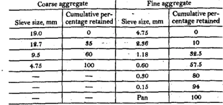
The coarse aggregate usedwas crushed lime-stone with a maximum nominal size of 19 mm; the fine aggre-gate was natural sand from the Ottawa region. The coarse and fine aggregates were separated into different size fractions andrecombined to a specified gradationセウ shown inA。N「セ・ 2.セィ・
ACI Materials Journal.V. 96, No. S. September-Cctober 1999. .,; ,
ReceivedMar5. 1998, and reviewed under Institute publication policies. Copyright
e
1999, Amencan Concrete Institute. All rights reserved, including the makingofcopies unless permission is obtained from the copyright proprietors. Pertinent discus·
sion willbepublishedin the ]uly·August 2000 ACI Materials Jount(J[ if received by
April I, 2000. .
551
LIB S2.5
0.60 57.5
O.SO SO
0.15
...
Pan 100
Cumulative per- Cumulative per-Sieve size, mm centage retained 'Sieve size, mm centage retained
19.0 0 4-.75 0
ASSESSMENT TECHNIQUES FOR CORROSION
OF STEEL REINFORCEMENT
Half-eell potential
The hsif-ceIl potentisl is an indication of the relative probB-bility of corrosion activity, and was determined according to ASTM C 876 with minor differences. In' the experiment, Hg/HgCl. electrode was uBed instead o( the Cu/CuSO,
ACI Materials Journal/September-October 1999
Ii.7 85 2.S6 10
_ . _ , , ,
-Coarse aggregate Fine aggregate
+.75 100
9.5 60
Steel rez7ifOrcemene-carbon
steel· reinforcing bars, '15 mmindiameter, were used in the test. Reinforcing steel bars were used as received.
Preparation and properties of concrete specimens
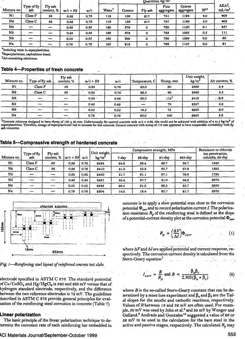
Concrete mixture9-
The proportions of the concrete mixturesare summarized in Table 3. . .セ
Properties 'lffresh concrete-
The concrete was mixed in alaI>-oratory counterwCurrent mixer for a total of 5 min. Theprop-erties of the fresh concrete, including the slump, air conterit, ,
and unit weight, were determined immediately after mixing,
and the results are given in Table4.The slump and air content
. of the concrete ranged from 70 to 175 mm, and from '.8 to 6.0%, reBpectively. The unit weight and temperature of the fresh concrete ranged from 2285 to 2il2 kg/m'. and 18.5 to 28.0 C. respectively.
Compressive
strength-Cylindrical BpecimenB, 100 x 200 mm insize, were。ャウッN」セエL and the compressive strengthofthe concrete
at 7,28, 91, and 865 days was detennined accordingtoASTM C
89 (Table 5). Thecompressive strength ofthe control portland ce-ment concrete at 28 days ranged from 18.i to 61.1 MPa. The con-crete incorporBting the Class C fly ash had a 2B-day compresBive strength of 55.8 MPa, which waB slightly lower than that of the control portland cement concrete with a wlc of 0.82 (61.1 MPa). The concrete incorporating the Class F fly ash had a 28-<!ay com-pressive strength of 86.i MPa, which was similar to that of the control concrete with a wlcofo.'h'l (87.7 MPa).
Resistance
tochloride-ion penetration:--
The resistance of theconcrete to the penetration of the chloride ions, measuredin
termB of the charge passed through the concrete (ASTM C 1202); waB determined on two di,kB cut from the top portion of 100 x 200 mm cylinders cured in a standard moist room for 28 days. The results presented are the averages from two concrete specimens (Table 5). The ASTM guidelines concerning the chloride-ion penetrability are given in Table 6.
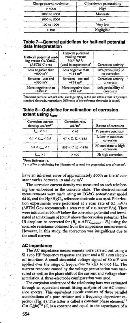
ChbJritk ponding
tesf-One reinforced concrete slab, 888 x 600x loSmm in size (Fig. I), was cast from each concrete mixture
and consolidated using an internal vibrator. Four pairs of rein-forcing bars 'were embedded in each concrete slab with concrete·
covers ranging from 13·to 76 mm, as shown in Fig.QNセNtィ・ slabs
were cu'red under'wet burlap for 7 days, and then .exposedto the laboratory air for approximately 50 days. The top surface of the slabs was ponded continuously with a,3.40% sodium chloride so-lution, and the corrosion progression of the steel reinforcement waS assessed using half-cell potential, line'ar polarization and,
AC impedance techniques after 2 and 6 months ofthe ponding. •
....
ASTM >-.-:.F:J.ly.,:a::sh:..._
TypeI ASTM
T
ASTMcement Class F
I
Class C Physical testsChemIcal analyses,%
Bogue potential compound composition
Silicon dioxide (Si02) 20.6 4<).7 88.9
Aluminum oxide (A40,) '.0 J7.9 19.4· Ferric oxide (FCt0,) '.1 29.9 6.1
Calcium oxide (CaO) 62.8 '.B 28.2 Magnesium oxide.(MgO) '.6 1.1 '.B
Sodium oxide (NlslO)
-
0.7 1.9Potassium oXideHセoI
-
1.6 0.'Equivalent alkali
0.8 I.B '.1
(Na,O+0.65BK(0) .
Phosphorous oxide (PliO.!!:)
-
0.' 1.5Titanium oxide (fiOe)
-
0.9 1.7Sulfur trioxide (SO,)
'.1
I., '.0Loss on ignition I.B '.0 0.'
..
Triealcium silicate (C,S) . 59.S
-
-Dicalcium silicate (<;5) 140.+
-
-Tricalcium aluminate(CsA) 6.8-
-Tetracaich;ml aluminoferrite (<;AF)9.'
-
-ACI honorarymembtr V. M. MalhotraisFセエゥウエ Emm'tus oftM lntnnationa,lセヲャイSlUtaina!JleDn>ekJpmmtofCnnmt and Conaete (ICON), CANMET. He is a,/orfMrエョュiセ
herofthe .AC!&aniofDirution alUi isall:adiwmnnJJtr ofnllmtttJUl.ACl conunittus. AClnumberMln--Hong Zhangisa researchscienJist attJu IntnnationalCntbYjOr Sus-tllinabk1NfJe1opmnltofCmuntaMCJncnte (ICON),CANMET, Ottawa,Canada.8/uis atMnIhtrofACI Conu"iltus ilS,Liglltweigltt and Aggregate CJncrete; iSi, Fly Alh and Natural Ponola1lS inConcrete; is''' SilkaFrnnein CONCrete; and tJu IntmrationaJ Adiv;-tinCommittee. Specfic gravity g.l5 2.67 2.62 Passing 45lAm,% 87.9
90.'
80.0 Specific surface, .BB "6...
Fineness Blairie,mll/kg Nitrogen absorption,-
-
-mll/kgCompressive strength 7-day 88.5
-
-of
51 mm cubes, MPa 28--day g9.7
-
-Water requirement.%
-
95.0-Pozzolanic 7-day
-
75.2 ....9activity index,% 'B-day
-
92.8 101.40 ) J. J.Beaudoinisaprinapalreuardt.qffiaratt1Je MaterialsLaIJorrJkJryofthebutiJllujorReuardl in Comtnution. His reuarril inkrests indUlkt1Je appikaJ!on of tiC impedana
セ incnnmtandCONCrek rtnaurrs.
• • • • • ", • • • •セwセ • •⦅BBLセ . . . ." '. . . ...c"tu.\..-UUIU1Jq;l-anaaa.HeIsaセアヲ、ci Hqュセ mittHii9, Ccrrwion ofMeliJls;'1 Conmu. Hu restaM intertstsindJldlセ
(l:tI'T'O-エゥッョセゥmゥVゥエゥョァ admixturrs, andmrrosiontUUJ11Mltandprottaion qfconcreteItr1IdJIra.
Table 1-Physical properties and chemIcal
composition of cement and fly ashes
552
coarse and fine aggregates each had a specific gravity 0[2.70, and water absorption 'of0.60 and 0.80%, respectively.
Superp/a.stici:ur-A
Bulfonated, naphthslene-formsldehyde condensate type superplasticizer was used in the concrete mix-.tures. The superplasticizer is a dark brown color solutioncon-taining402%solids.
. Air-entraining a.dmixture-A
multicomponent synthetic . resin type of air:-entraining -admixture was used in all theconcrete mixtures.
-! .
i
i
·
.
Quantities, kg/m'" Typeof fly Flyash .
Fine Cparse AEAt;
l
Mixture no, , ash content,% w/c+FA wle Water- Cement Flyash aggregate aggregate SP+ mL/m'セ NI Class F 58 0.76 119 15B 751 1124- ',0 toS
i
0.32 217 No Class C 58 0.82 0.76 119 158 017 ,7+7 1120 5.0 toS•
'"
Ns-
0.52 0.S2 100 S7B 0 7B9 1150 9.1 '57'"
•
N' 'I 0.4S 0.+8 160 S70 0 70S 1085 0.5 III1
NB-
0.55 0,55 IB5 800 0 7SB 1099 0.0 60,
N. 91 セ-
-
0.76 0,76 IB5 018 0 7B8 11+7 0.0 .. 'I-Including water in superplasticizer,
j'
tsuperplasticizer, naphtahlene based..セ tAir--entrainingadmixture.
ゥセ
Gセ
Table 4-Propertles of fresh concrete
,
"" Fly
ash Unit weight,
.;,
." Mixture no. Typeof flyash content,% w/c+FA wle Temperature, C Slump, rom kg/mil Air content,%
" " NI Class F 58 0.82 0.76 28.0 90 2869 U 7- NO Class C 58 0.82 0.76 22.5 90 2869 6.5 Ns
-
0.82. 0.82 28,0 175- 24012 ,;".8 (i\ N5 0.+8 0,48-
70 2SS!7 5;2 'J:i:; NB
-
-
0.65 0.55 18.5 75 lliS5 B.ON' 0.76 0.76 20.0 100 2285 5.6
·Concrete mixtures designed to have slump of JOO±iOmm. Unfortunately. for control concrete withwlc= 0.S2, this could notbeachievedwith addition of 4 to 6 kg/mSof
ウオセイーャ。ウエゥ」ゥコ・イN Therefore, dosageof superplasticizer hadtoincrease forthis concrete. Control concrete with slump of 176 rom appeared to have comparable workability with fly
as concretes. ' .
,
,"
'iTable S-Compressive strength of hardened concrete
:
J
Typeof fly Flyash Unit weight, Compressive strengt!), MPa Resistance to chlorideion penetration,.".
, Mixture rio. ash content,% w/cf.,FA wle kg/ms 7-day 28...<Jay 91-day 565-day columbs, 28-dayNセ NI Class F ·58 0.82 0.76 2424 24.6 36.4
".7
56.7 IttO NLセ No Class C 58 0.82 0.76 2410 41.0 55.8 60.7 67.9 1895.,
Ns-
-
0.82 0,82 21<50 51.7 61.1 67.1 78.6 1780 " N5 0." 0.48 2881 85.4- 87.7 tl.O 48.2 8970 .... N6-
- 0.55 0.55 2848 26.5 81.0 85.5 85.7 5250 '. ',: N. 0.76 20.7 2,1.7 5970 エLセ 0.76 osot It.6 18.4,
'.f!
.concrete is to apply a
ウャセキ
potential scan close to the cOrTosion'.
QMLZZNBB⦅MBLLLMNcセセAjヲ[ᄋᄋᄋZwャャセセZ[セセZZ[Z[⦅[セZZ⦅セ[Z[[MG
___
.1-セ
potentialcI>corr and torecord polarization current 1 Thepolariza-• ,i;: tion resistanceRpof the reinforcing steel is defined as the slope
f
,. ;;
[[スセ
i : :
ZfZ[セNセセセLセセMセMMML
,-, ,--
-1'
r
ofa potential-.:urrent density plot at the corrosion potentialw_
i
.,
セ[[セNセNZセNセセセZイHセZZ
[1.::
if [:. ''"
Hセセキ・NB
I
セ Rp(I)
1+----+:
! !! I I_I '=
, ! !!"Nll
LO,
' L-.-c. \ .-.- ---_.\I
where AVarid'Ai are
。ーーャゥセ、Gセエセセエゥ。ャM。ョ、
currentイ・セーッョウ・LGセ・M
·.
15nm .833nm
',- spectively. The corrosion current density is calculated from the
i
:to
,
-•
Stern-Geary equation7-Fig. I-Reinftrcing 'teellayout
'If
rei'ifOrced ctJ1lCrete te,t ,lab,.
,
ャ」セイイ
=
!!...
andB=
1l.lle
(2)electrode specified in ASTM C 876. The standard potential R
p
,
2.303<1l.
+
Il
e),
I
ofCu/CuSO,and Bg/HgCI,isUセo and 268 mV ver8US that of
•
hydrogen standard electrode, respectively, and the difference where B is the s<>-called Stern-Geary constant that can be
de-between the two reference electrodes is 72 mY. The guidelines termined by a mass los8 experiment and
Il.
andIlh
are the Taf-,
described in ASTM C 876 provide general principles for eval- eI slopes for the anodic and cathodic reactions, respectively.
uationof the reinforcing steel' corrosion in concrete (Table
7).
Values ofBbetween ISand 52 mV are often used. Forexam-linear polarization
ple,5o mVwas used by John et al.s and 55 mVbyWenger andGalland.' Andrade and Gonzales'o suggested a value of26 or',
The basic principle of the linear polarization technique to de- 52 mV to be used in the calculation for the bare steel in the
tennine the corrosion rate of each reinforl;:ingbar embeddedin active and passive stages, respectively. The calculatedRpmay
-Standard potenrial ofCu/CuSO... and Hg/HgC\ is.540 andi68mV that ofhydrogen standard electrode. respectively. Difference'oftwo reference electrodes is 72 mY.
-From Reference IS.
t)m of No. 5 reinforcing bar (diameter of 15 mm) has g'eQJ?etrical area of4-70 cmi.
Fig. 2-Equivalent circuit used in AC impedelu:e fitting prouu consisting qf three parallel combinations qfpure resiJWr
and.fre-quency dependent capaciror. Note:
He
andC,
=
concrete resistance and matrix solidlliquid inteiface capacitance;Ri andG
=
steelI concrete inteifacefilm resistance and capacitance; andRpand Cd]=
steel polarization resiJWnce ond dcuble-layer capacitance
pure capacitor), introduced to account for the shape of the
de-pressed complexーャッエセ The three resistor/capacitor circuits
rep-resent the concrete matrix, interface mm and steel surface
corrosiori processes, respectively. The detailedRpdetermination
procedure is given elsewhere.Ii The corrosion current density
was calculated by knowing the polarization resistanceRp
deter-mined through$computer equivalent circuit simulation and
us-ing theStern-Geary equation. ABvalue of 26 mV for active
corrosion, and the
R;
values obtained from the impedancespec-tra fitting were applIed in the calculation. .
A guideline for the estimation of corrosion extent using cor-rosion current density is given in Table 8.!"
RESULTS AND DISCUSSION
Resistance to chloride-Ion penetration
(ASTM C
1202)
.
.
The HVFA concretes had higher resistance to chloride-ion penetration thrm the ,control portland cement concrete as lndi-cated by ASTMC 1202 test. The accumulated charge passed at 28 days was 1440 and 1895 coulombs for the HVFA concrete incorporating ASTM Class F and Class C fly ash, respectively. These values were lower than 1780 coulombs for the control
concrete with awlcofo.S2.According to ASTM C 1202,
con-crete with a value ofless than 1000 coulombs is considered to have an excellent resistance to the penetration ofchloride ions. Other published data on the investigations dealing with HVFA concrete show that the values of the charge passed through concrete decrease dramatically with age, and values as low as about 250 coulombs have been reported for tests performed on the HVFA ooncretes at 91 days.'
Electrochemical measurement
Half-cell potential qfsteel reirifOrcement in concretesiaM-The half-cell potential or corrosion potential is often used as an ih-.dication of the relative probability of the corrosion activity. The data analysis guidelines described in ASTM C 876 provide
general principles for the・カ。ャオ。セゥッョ of the reinforcing steel
cOrrosion in concrete. Generally, the more negativeーッエセョエゥ。ャ
readings are associated with the higher probability of the rein-forcing steel corrosion. This approximation is quite accurate when chloride ions are present.
The half-cell potentials at the reinforcing bars in the tWo
HVFA concrete slabsandthe four control portland cement
con-crete slabs, measured after2 and 6 months of ponding with a
S.4%sodium cWoride solution, are given in Fig. sea) and (b).•
The letters
a,
b,t;4,.
e,j;
g,
andhrepresent the concrete cover tothe reinforcing steels of IS, 25, 51, and 76 mm, respectively. The half-cell potential readings obtained from the reinforcing steels embedded in the HVFA concretes and the control concrete with aw/cofO.82are relatively noble with values less negative than -100 mY. These readings indicate low probability of the rein-forcing -steel corrosion. However, the first two reinrein-forcing bars
aandhwith a cover thickness of 18 mm embedded in the control
concrete withキO」セ 0.48 depicted much more negative half-cell
Very low Low High Moderate Negligible Chloride-ioll penetrability >4000 <100 100to1000 1000 to 2000 2000 to 4000 Charge passed, coulombs
Corrosion current Corrosion rate,
density,
J.1A/
cmi- llA/mt Extent of corrosionlrorr<0.1 . <47 P: passive condition 0.1<lawr< 0.5 407<C.R.<285 L:low to moderatecorrosion
0.5<lrorr<1 285<C.R.<4070 M:ュッ、・イ。エセ corrosionto high
Iawr> 1 >40.70 H: high corrosion Half-cell potential
Haif-cell potential read- イ・。、ゥョセ versus
ing versusCu/CuSO... Hg/ gCl,
(ASTM C S76) (used in experimentt Corrosion activity
Less negative than Less negative than 90%ーイッ「。「ゥセゥエケ of
""i!OOmV -li8mV no corrosion
Between -200 and Between -128 and Corrosion activity
-S50mV -278 mV uncertain
More negative than More negative than 9O%·probabilityof
-S50mV -278 mV corrosion
AC Impedance
The AC impedance measurements were carried out using a Sl 1255 HF frequency response analyzer and a SI 1286
electri-cal interface. A small sinusoidal voltage signal of 80
inv
wasapplied over the range offrequencies 75 kHz to 0.05 Hz. The current response caused by the voltage perturbation was mea-sured as weU as the phase shift of the current and voltage char-acteristics.· A three-electrode confi'guration was used.
The cOJ1'osion resistance ofthe reinforcing bars was estimated through an equivalent circuit fitting analysis of the AC imped-ance spectra. This equiva).ent circuit consists of three parallel combinations of a pure resistor and a frequency dependent
ca-pacitor (Fig. 2). The latter is called a constant phase element,II
C
=
C.JjJl)-« (C,is a constant and equal to the capacitance of aTable 8-Guldeline for estimation of corrosion
extent using ,
CO"Table 7-General guidelines for half-eell potential
data Interpretation
have an inherent error of approximately 200% as the B con-stant varies between 18 and 52 mY.
The corrosion current density was measured on each reinforc-ing bar embedded in the concrete slabs. The electrochemical measurements were, made using an EG&G potentiostat model 6810, and the Hg/HgCI, reference electrode was used.
Polariza-tion experiments were performed at a scan rate of0.1mV/s
(ASTM G59 recommends a scan rate of
<
0.1667mV/s). Theywere initiated at 20 mV below the corrosion potential and termi-nated at a maximum of20 mV above the corrosion potential. The
. IR drop can be corrected for
(R
p= lJ,V/I""""",r R,)
using the·concrete resistance obtained from the impedance measurement. However, in this study, the correction was insignificant due to the small current.
..
..
1'ol1IIrllI_ 1'IIItIIncl_ PIll*IIl-.. PldMolOlflWt
_ _ l«r*llll ⦅Hセ PdiGャャャiエャiセ ⦅セ セMセ セMセ __セ N m M セ
-' .I.ll! i .(\Ill! f Q{ClZS I Ial41U_ i 1 ·(·151 ... \ .{Il61""" IL;:;;J
I M A _ 1'MA0DI'lllItlI ClloII'1Ill ClIAC . . wecof'A/-o,:a WlC+fAJ-ua ,-HWA-* IM'A_ 1'OtlIorId_ PorIIftd_ セ ⦅ PorIInlI_
ClMF8Ih a-c... __サ セ ⦅ セ odャiョiiャセ -.lI(coI*olI
W'(C"'AJ-o.:sz セ⦅ッLg wc-o.a ,WC-O,43 ,we_OM wc-o.'/'$
-
-,,;;;'. :'ii.
Fig. 3-Half-cell potentials
'If
two HrFA COTU:1'ete slabs (N1 and . N2) andfoureontrol slabs (N3 to N6) measured qfter: (a)2months;and (b)6months
'If
sodium chkJritk solution ponding.potential values
«
-300mY) even after2months ofponding.After 6 months ofponding, the reinforcing bars with 25 and 51 'mm concrete cover in the concrete'slab with a w/cof 0.76, and
with 25 mm concrete cover in the concrete slab with a wlc of
0.55 showed the potential values more negative than-500mY.
These observations indicated a high probability ofcorrosion of the corresponding reinforcing bars.
Corrosion current determined using linear polarization
tech-nique-
The linear polarization technique is a useful, nonde-structive, .relatively fast, cost-effective, and quantitative approach for corrosion assessment ofreinforcecl concrete. Theunit of the corrosion rate is normally expressed by
IJA/cm'
ormA/mi!. As it is difficult to determine accurate reinforcing bar surface area, it may be more appropriate to use the unit length instead of the unit area to represent the reinforcing steel corro-sion rate. Therefore, a unit of J,1A/m, meaning the corrocorro-sion current density ofa meter-long reinforcing steel bar, is used in the disc\,Jssion that follows.
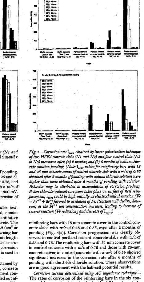
Fig.セH。I and (b) illustrate the corrosion rate1=obtained by
the linear polar,ization tec.hnique of the, t.wo HVFA ,concrete
slabs
(1"1
and N2) and the four controlportland cementcon-crete slabs (N5 to N6). The measurements were carried out af-ter 2 and 6 months ofponding with the chloride solution. The
values of theItOrrfor .all the reinforcing bars in HVFA concrete
slabs were less than i6 J.lA/m regardless of the concrete cover even after 6 months. This indicated that the HVFA concrete had excellent 'resistance against chloride-ion penetration. Sim-ilar results were observed in the co.ntrol portland cement
con-crete with aキO」ッヲoNURセ In contrast, theleorrvalues were much
'higher- for the reinforcing bars with 15 and 25 mm concrete cover in the control concrete slab with. a w/c of 0.76, and for ACI Materials Journal/September-October 1999
Fig. +----Corrosion rote
i"",
obtainedIi)'
linear polarization technique'If
two
HVFA COTU:1'ete slahs (N1 and N2) andfour control slahs (N3 wN6) measuredqfIer: (a)2months; and (b)6monthS 'lfsadium chlo-ride solutian ponding. (Note:i",,,valuesfor rei/!fim:ing ba.rs with 13 and25mm COTU:rete covers'If
control COTU:rete slah with awlc'If
O. 76obtained qfter2months 'lfponding with sodium chloritk solution were higher thon those obtained qfter6months
'If
ponding with solution. Behavior may be attributed W IU:CUmulation'If
corrosian produds. Wkenchloride-induad corrosion takes plaJ;e on surface'If
steel rein-forcement,i",,, could be high initiJllry as elektrOehemiall reaction [Fe=
Fe+'+
2e"]fovored Woxidabon'If
& Reaction win tkcline,Iww-ever;
as
theFe+Sion concentration increases, leading
toincrease of
reverse reachon [Fe reduction)and tkcrease
'!fI",.".)
reinforcing bars with 15 mm concrete cover in the control
con-crete slabs with wlc ofPNセS and 0.55, even after 2 months of
ponding (Fig. 4o(a)). Corrosion progression was clearly
ob-served in control portland cement concrete slabs with
wit
of0.55 and 0.76. The reinforcing, bars with 51 mm concrete cover
in control concreteセゥエィ awlcof 0.76 and those with 25-mm
concrete cover in control concrete with -
a-
wlc
'of
0.55 showedsignificant increases InGエィセM」ッイイッウゥッョ rate after 6 months of
ponding with the 5.4% chloride solution. These observations are in good agreement with the half-cell potential results.
Corrosion current determined using AC impedance
technique-The rates of corrosion of the reinforcing bars in the six con-crete slabs werealso determined. using the AC impedance tech-nique. An equivalent" circu,it fitting of the experimental impedance spectra procedure was applied to estimate the value
of the polarization resistanceR .A typical example of the
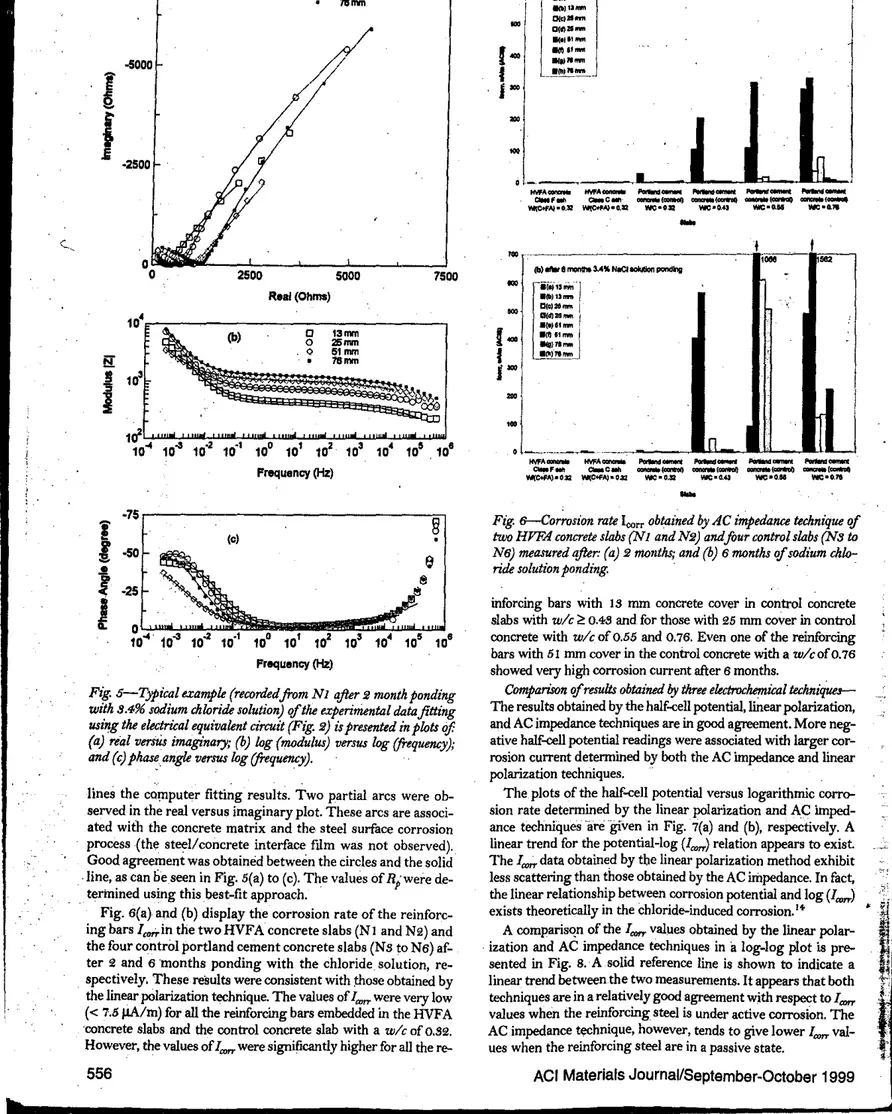
ex-perimental data fitting using the electrical equivalent circuit models, as described. in Fig; 2, is presented in, the plots of real versus imaginary (Fig. 5(a)), phase angle verSus log
(frequen-cy)
(Fig. 5(b)), and log (modulus) versus log (frequency) (Fig.5(c)). The circles represent the experimental data,and the solid
555
-I
n..JL--U
PI:lrWrlIl-.t セMNN lIalIIIncI_ l"wIIInl_ _ _ 1ea'*'OIJ _CODnfllI} _(I;IlnhI) _CODIIhllwe-OR WC-G.43 WC_O.N WC_G.lI
-,
M⦅N⦅N⦅セセMM HVFA_ HVFA_ e-FIIIIl c.c .... WI(C+FA)-OJ:l W{C+f'Aj-O.3:2'"
LMMMMセBMMM..,.,.,,_ I M ' A _ Pldnl_ ...0IllIMl JIOIIIIIlI-...nt PiMItlIIIClIMIOIl
ClMIf. e:a-c... _ _H セ ccno:r.-I-' _ _セ _ _H セ
wサcヲヲセNッLャiR セNッNZウ。 wrc-O,:t:I W'C-o.+l wrc-o.lllI NC-o.,.
'"
..
.,
\./ -5000I
-i
·2500QセGMZGBGBBGMZAMGMBBB]LBBBG[cBBBM[[uBGGGGGGGGGGGGGMZGMGGGGGGG]GNャャャlZLBLBLLLMZLMLBLLB
10" 10" 10" 10·' 10· 10' 10' 10' 10' 10'. 10· Frequancy(Hz) <..,'"
0 0 2500 5000 7500..
R.al(Ohms) 10'..
(b) :lSmmtommI ..
"mmI
B:
78mm!I
10'j'"
i
'"
. 7 5 r - - - = § (0) •e
I!l 10· 10' 10' 10' 10' 10' 10· Froquancy(Hz)Fig.
5 -Typical example (recordedfrom
NlojIer
2month ponding
with
9.4%sodium chlorilk solution) qfthe experirizental datafitting
using the electri£al equivalent circuit (Fig.
2) is presented in plots
of
(a) real versUs imaginary;
(b) log (modulus) versus log (frequency);
and
(c) phase angle versus log (frequency).
lines the
」セセーオエ・イ
ヲゥエエゥセァ
results.Two partial arcs wereob-served in the real versus imaginary plot. These arcs are
associ-ated with the concrete matrix and the steel surface corrosion
processHエィセ steel/concrete interface fIlm was not observed).
Good agreement wasobtained between the circles and the solid
,line, as can lieseen in Fig. 5(a) to (c). The values of Rpwere de-termined using this best-fit approach.
Fig. 6(a) and (b) display the corrosion rate of the
reinforc-ing barsl,.,;.inthe two HVFAconcrete slabs (Nl and N2) and
the four control portland cement concrete slabs (N3 to N6)
af-ter 2 and 6 'months ponding with the chloride, solution,
re-spectively. These results were consistent with those obtained by the linear polarization technique. The values ofl""" were very low
«
7.5 jJA/m) forallthe reinforcing bars embedded in the HVFA'concrete slabs and the control concrete slab with a
wlc
of 0.32.However, the values ofl""" were significantly higher for all the
re-Fig. 6--Corrosion rate
100"obtained by AC impedance technique qf
two
HVFA concrete slabs
(Nland
N2)andftur control slabs
(N3toN6) measured
ojIer:
(a)
2months; and (b)
6months 'ifsodium
chlo-rilk solution p o n d i n g . '
'
inforcing bars with IS mm concrete cover incontrol concrete
slabs with
wlc
セ 0.43 and for those with 25 mm cover in controlconcrete with
wlc
of 0.55 and 0.76. Even one of the reinfurcingbarswith51 rnm coverin the control concrete
with
aw/cofO.76showed very high corrosion current after6months.
Comparison 'ifresults obtained by three electrochemual
エ・」ィョゥセThe results obtained by the half-eell potential, linear polarization,
and AC impedance techniques are ingoodagreement. More
neg-ative
half-cell
potential readings were associated with largercor-rosion current determined by both the AC bnpedance and linear
polarization techniques.
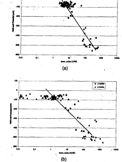
The plots of the half-eell potential versus logarithmic
c0rro-sion rate determined by the linear polarization and AC bnped-ance techniques '.regiven in Fig. 7(a) and (b), respectively. A
linear trend for the potential-log(l"",,)relation appears to exist
TheI"""data obtained by the iinear polarization method exhibit less scattering than those obtained by the AC impedance. In fact,
the linear relationship between corrosion potential and log
(l"",,)
exists theoretically in the chloride-induced colTOsion. lf
A comparisqn of the l"""カ。ャセ・ウ obtained by the linear
polar-, ization and AC impedance techniques in • log-log plotis
pre-sentedin Fig. S.'Asolid reference line is shown to indicate a
linear trend between the two measurements.Itappears that both
techniques are in a relatively good agreement with respect to It:tm' values when the reinforcing, steel is under active
corrosion.
The AC impedanceエセィョゥアオ・L however. tends to give lowerlrorr val-ues when the reinforcing steel are in a passive state.;,I
,I
.ᄋiセGN[B
I
;1
\r
556
ACI Materials Journal/September-October 1999
;" ,1C1l1l1 fliollo
,
..
"
...tlHI.
-,4
--,"'.-
. L. __ ... _. .1 ,,---, ! I セM !., I
J
...
.,
,
...
No. Concrete mixture ISmm 2Smm Stmm 76mm
Nt HVFA concrete, Class Fash,w/{c+ FA)
=
0.82 Low lッセ Low LowN. HVFA concrete, Class Cash, w/(c+FA)
=
0.82 Low LowLow
LowNs Control Portland cementconcrete,w/c= 0.82 Low Low Low Low
N5 Control portland cementconcrete,w/c
=
0.48 High Low Lo'\" LowN6 Control portland cementconcrete,wlc High . High Low. Low
=0.55
nセ Control portland cementconcrete,w/c=0,76 High, High Middle Low
Table 9(a)-Probablllty of corrosion after
6
months
evaluated by half-cell potential method
..
'd .Fig. B-Log-wg.plot
ofl,o"
values obtained by
bothUnear
polar-i%ation (LPM) and AC impedance (ACIS) techniques.'
.,
...
•
..
- - - " !••Mセ .. -- ----C-j'.
---"--"'.,••----c--c---j (b)...
0,01]MMセZZ⦅MMMMM」⦅MMMMMM 0,1 !II 100 1001)1IoIf,lIMIICAClS)
...
ェMMMGMMMMMMMMセセBB .... j-(a)
I
j:f-I-jMセMMセ
...セiMMMM」MセMMMMMM⦅GMMMBBI
Z」⦅M]]⦅MMセMMMMMMMZLNNNMMMNM⦅
0.0, 0.1 10' 100 1DoIr,"'-(IJ'lIIl)','
Fig.
7-Plotsof
half-all potential versus wgan'thmi<: corrosion
rail!defm'mined? (a) Uneorpolarization;
and(b) AC impedana techniques..
Note:Low=half-eell p?tentlal less negauve than-128mV, indicating' 90%
probabil-ity of no corrosion; MIddle= half-eell potential between-128and-i78m\';ゥョ、ゥ」。エセ
ing corrosion activity is uncertain; and High =.halfooeell potential. more negative
than-i.7SmV, ·indicating 90% probability ofcorrosion. , .
•
Note: P - passIvei L "";'low; and M _ moderate.557
Table 9(b)-Severlty of corrosion after 6 months
evaluated by linear polarization technIque
No. Concrete mixture lsmm 25mm 5lmm 76mm
NI HVFA concrete, Class Fash. P P P P
w/(e+ FA)=0."
N. HVFA concrete, Class Cash, P P P; P
w(e+ FA)=O.s.
N. Control portland cementconcrete,.w/c=0.82 P P P P
N5 Control portland cementconcrete, M P p. P
w/c=0.48
N6 Control portland cementconcrete, L L P P
w/c=0.55
N' Control portland cementconcrete,w/c= M L L P
0.76
-tion. Higher con-osion currents were observed for the steel
rein-forcing bars embedded in the control concrete withw/eセ 0.103. As
expected, the poorest performance was of the reinforC.ing bars in
the control concrete. with a
wit
of0.76 where corrosion of there-.inforcingsteelwas detected even with 61 nun concrete cover.
Sig-nificant corrosion of reinforcing steel with 13 mm cover was also
found in other control concrete slabs with
wit
of 0.4S and0.65 after 6 months ponding with the chloride solution. The results confirmed the evaluation by the half-cell potential measurement.
Cct7YJsion ofsteel reinforcement in concrete-
Theconcrete cover isa physical barrier that impedes the chloride-ion penetration, thus protecting the reinforcingsteel from corrosion. Good quality and appropriate depth of concrete cover can significantly influence the rate of carbonation, and the diffusion .of corrosion-inducing
species into the concrete-steel interface region. The thicker this cover is. the longer it takes for the chloride ions to reach the surface of-reinforcing steel. A greater protection against
corrosion is therefore assured. .
The,corrosion cOnditions of the steel,reinforcementinthe six
reinforced concrete slabs were evaluated after 6 months of the chloride ponding. Table 9(a) summarizes the corrosion
probabili-ty ofsteel reinforcements by means ofhalf-<:ellpotential according
to ASTM Standard C 876. The HVFA concretesaodthe control
concretewitha wlcof0.32showed no probability of corrosion
even on the steel reinforcing bars with 13 rp.m concrete cover. The excellent performance·ofsteel reinforcement in HVFA concrete is .
due to the very low permeability of the concrete.ISForallother
control eoncretes
with:wlt
セ 0.403, the first two reinforcing steelbars with 13 mm cover、セーゥ」エ・、 high probahility ofcorrosion. For
concrete with a
wlcofo.76,
even the reinforcing bars with 26mIncover showed high probability ofcorrosion.
. Table 9(b) andセH」I give a summary of the corrosion conditions
ofthe steel reinforcement in the six concrete slabs evaluated by the linear polarization and theAC impedance techniques, respectively. It is clear that the HVFA concretes and the control concrete with a. wlcofo.32 provided adequate protection to the reinforcing steel
from corrosionin tenus of mitigating the chloride-ion
t
I
;,
j
Strength Development of High-Volume Fly Ash Concrete,"CementaNi
. Concrtte Composites,V. 12, 1990,pp.RVXᄋセWPN
S. fセャ、ュ。ョL R. F.;Garette, G.
G,;
ana
Malhotra, V. M., "Studies onMechanism of Development of Physical and Mechanical Properties of
High-Volume Fly Ash Cement Pastes,," Ctmmland ConcreteComposita,V.
12, 1990,pp.2+5·251. '.
+.
Berry, E. E,;Hemmings,ft.; and Cornelius, B. J.""Mechanisms ofHydration Reactions in High Volume Fly Ash Pastel! and Mortars,"
Ctmnrt and Concrete Composites,V. 12, 1990, pp. 25l:H!61.
6. "Investigation of the Long-Term Characteristics of
High-Perfor-mance Concrete," Reportby Trow Consulting Engineers, Ltd., under
CANMET contract2S+4()..7-1009/oo1/SQ,Mar. 1998.
6.Malhotra,
v.
M.,and Ramezaniaripour, A. A., "Fly Ash in Concrete,"CANMET/Natural Rtsourcu c.nada, CANMET, MSL 9<-+5(IR). 2nd revised edition, 199+,297pp.,"
7. EG&G, "Linear Pola,rization,"Pn'ncetonApplied Research Application
N,0te-l«J,andNote-HB,'Tafel Plot."
8. John,D, E,;Searson,P.C.;and Dawson, J. L., "UseofAC Impedance
Technique in Studies on Steel in Concrete in Immersed Conditions,"
Brit-ish Corrosion JOIlNUllV.16, 1981, pp. 102·106.
9. ,Wenger"F.,and Galland,J., Gセョ。ャケウゥウ of Local Corrosion of Large
Metallic Structures or Reinforced Concrete Structures by Electrochemical
Impedance Spectroscopy,"Electrothimica Acta,V. 55,1990, pp. 1578-1578.
10.Andrade,C,and Gonzales, J.aLセ "Quantitative Measurements of
Corrosion Rate'of Reinforcing Steels Embedded in Concrete Using
Polar-ization Resistance Measurements,"Werkstoffi und Korrosion, V.29, 1978,
pp.515·519.
11. Cole, K, S" and Cole,R. H., "Dispersion and Absorption in
Dielec-trics,t:Alternating Current Char'acteristics,"Journal
of
Chemical Physics,V.9, 19401, pp. .9+.1-:351.
12. Gu,P.;Elliott, S.; Hristova, R;Beaudoin, J.J.;Brousseau, R.; and
Baldock, B., "A Study of Corrosion Inhibitor Performance in Chloride Contaminated Concrete by Electrochemical Impedance Spectroscopy,"
ACI Maten'als Journa4V.9+, No.5,' Sept...oct. 1997, pp, 885-595.
18. Broomfield; J.P.,"Assessing Corrosion Damage on Reinforced
Con-crete Structures,"Corrosion and Corrosion Protection on Steel in Concrete,V.
I, Proceedings of International <;onference, University of Sheffield, UK,
R.N. Swamy,ed.,199+;'pP. 1-25. ., , .
1+.;O:u', P.; Beaudoin,J.J.; Tumidajski,P. J.; andmセゥャカ。ァ。ョ。ュL N. P.,
"Electrochemical Incompatibility of Patches in Reinforced Concrete,"
Con-crete InternationalV,19, No: 8, Aug. 1997, pp, 68-72.
, 15. Bilodeau,A.;sゥカ。ウオイゥ」ゥセイ。ュL V;Painter,K.E.; and Malhotra,V.M.,
"Durability of Concrete Incorporating High Volumes of Fly Ash from
Sources in U.S.,"ACIMaterials Journa4V. 9'1, No. I, Jan.-Feb. 19940, PI'- 5-12.
Nflfltl " :011passive, L - low, and H - high.
ACKNOWLEDGMENTS
HィGャャャGセ|ャャ acknowledgment ismade to Electric Power Research Institute
(I'illltl) jlfPllloAlto.Calif.,for,funding oftheproject.Thanks are due, to Nath-"IltiHᄋィBセGャiエャャャN Bruce Baldock, GlendonPyeand Bob Myers ofNRC/IRC, and
It,HGィエGセイゥャGイ nnd A. Ferro ofCANMETfor their helpwith experimental work.
CONCLUSIONS
'I'll" IIVFA
concretes had higher resistance to chloride-ion pfi,wll'ntion than the control portland cement concrete asindi-,,"h.d
lIy
ASTM C 1202 test. ''I'll"
performance of the reinforcing steel bars in thehigh-vnhllll"l1y
ash concretes after 6 months ofpanding with a 3.4%iャLセ、ィャヲャャ chloride solution was excellent. ThJre was no
signifl-'en"t /lweIcorrosionエセセセセァ place on.セNィ・ reinforcing steel
em-IW4hlt'll
in
the HVFA concrete・セ・ョ with'lS mm concrete cover.'l'hl, performance of the HVFA concrete is equivalent to that
ofth,' ",mtrol concrete with aw/COfO.32,and is better than the
(lOnll'ol concrete with
wlc
セ O.4S. ISIJ.Clliflcant corrosion rates were observed for the reinforcing
IIu'l'l (Imbedded in control portland cement concrete with
wit
It
(l.·M.As expected. the poorest performance was of the controlCIOIWI,(.!t· with
a
wit
of
0.76, where 'corrosion of reinforcingHh'I.' WIISdetected,・カセョ with51 tnm concrete cover.
N'" Concrete mixture ISmrn 25mm ,51mm 7Gmm
-
IfVFAconerte,Ctass FHI
llIli. w/(c+FA) ::::0.32 p P P P hセ J10001h,IVFAw/{cconcrete,+FA)Class C::::0.$2 p P P Phセ (:untrol portland cementconcrete,wlc:::: 0.82 p p p p
-
Omtrol portland cement H pP P
hセ concrete,wIt:::: 0.48
1'111 (:cmtrol portland cement,:oncrete,wlc::;0.65 H H P P
hセ L:nntrol portland cementconcrete,wit:;::0.76
if
L L P-
-REFERENCES
I, ml\'t\kau. A.;. Sivasundaram, V; Painter, K. E,; and Malhotra, V. M.• , "ll\tl'llhllil)'of Concrete Incorporating High-VolumeFlyAsh from Sources
i·· I