Publisher’s version / Version de l'éditeur:
Electrochimica Acta, 34, 2, pp. 229-232, 1989
READ THESE TERMS AND CONDITIONS CAREFULLY BEFORE USING THIS WEBSITE.
https://nrc-publications.canada.ca/eng/copyright
Vous avez des questions? Nous pouvons vous aider. Pour communiquer directement avec un auteur, consultez la
première page de la revue dans laquelle son article a été publié afin de trouver ses coordonnées. Si vous n’arrivez
pas à les repérer, communiquez avec nous à [email protected].
Questions? Contact the NRC Publications Archive team at
[email protected]. If you wish to email the authors directly, please see the
first page of the publication for their contact information.
NRC Publications Archive
Archives des publications du CNRC
This publication could be one of several versions: author’s original, accepted manuscript or the publisher’s version. /
La version de cette publication peut être l’une des suivantes : la version prépublication de l’auteur, la version
acceptée du manuscrit ou la version de l’éditeur.
Access and use of this website and the material on it are subject to the Terms and Conditions set forth at
Involvement of surface oxide films on iron in halide-induced pitting
Bardwell, Jennifer A.; MacDougall, B.
https://publications-cnrc.canada.ca/fra/droits
L’accès à ce site Web et l’utilisation de son contenu sont assujettis aux conditions présentées dans le site
LISEZ CES CONDITIONS ATTENTIVEMENT AVANT D’UTILISER CE SITE WEB.
NRC Publications Record / Notice d'Archives des publications de CNRC:
https://nrc-publications.canada.ca/eng/view/object/?id=a2b79a8d-83d9-4cf1-8f6b-68b6cba869ca
https://publications-cnrc.canada.ca/fra/voir/objet/?id=a2b79a8d-83d9-4cf1-8f6b-68b6cba869ca
IN VOLVEMEN T
OF S URFACE
OXIDE
FILMS
ON IRON
IN
HALIDE-IN DUCED
PITTIN G
zyxwvutsrqponmlkjihgfedcbaZYXWVUTSRQPONMLKJIHGFEDCBA
Division of Chemistry,
JENNIFER A. BARDWELL and B. MACDOUGALL
National Research Council of Canada, Ottawa, Ontario, Canada, KlA OR9
(Received
3April
1988; in revised_/iorm 20 June 1988)Abstract-Bromide-induced pitting of Fe is triggered by a critical state
zyxwvutsrqponmlkjihgfedcbaZYXWVUTSRQPONMLKJIHGFEDCBA
of the passive oxide film. The statecorresponds to a specific thickness of the oxide which depends on the concentration of bromide ions, but not the anodizing potential. In addition, pitting will only occur if the critical state is established in -K 10 s. The critical thickness for pitting is linearly dependent on the logarithm of the concentration of halide ions. Similar slopes are obtained for chloride and bromide ions, however, the critical thickness for Br- is greater than for Cl- at the same conceptration, reflecting the more aggressive nature of the Cl-. Once development of the passive film has passed thb critical stage, pitting becomes very unlikely, even if the potential is held well above the pitting potential. Partial cathodic reduction experiments demonstrate that a thinner film does not pit more rapidly than a thicker film; instead more charge must pass for the thinner film to reach the critical state prior to pitting.
zyxwvutsrqponmlkjihgfedcbaZYXWVUTSRQPONMLKJIHGFEDCBA
INTRODUCTION
Pitting of Fe is induced by the presence of halides in otherwise non-aggressive solutions. Pitting will occur after an induction time, c, if the potential exceeds the critical pitting potential, E, [ 141. Both these quanti- ties depend on the concentration of halide in solution, with a minimum concentration required for pit init- iation. In general, the halides are aggressive in the order Cl- > Br- >l-. Despite numerous investi- gations, the mechanism of pitting remains a contro- versial topic[5].
In recent work, it has been demonstrated that Cl-- induced pitting of Fe in pH 8.4 borate buffer solution is associated with a critical stage in the development of the passive film[6]. This state corresponds to a specific thickness of the-oxide film which is &dependen<of the auplied potential, but demndent on the W-1. Since tgd passive film & Fe is iormed with 100% efficiency in pH 8.4 borate buffer solution, a quantity Q,(pit), the anodic charge passed prior to pitting, can be defined. A potential-independent Q,(pit) was shown to be consistent with the experimentally observed dependencies of
E,
on [Cl-] and of 7 on potential. The purpose of this paper & to show that these results also aDDlv to Br--induced vitting of Fe. In addition, the &i-mum halide concentration required for pitting is explained in terms of a critical stage in the devel- opment of the passive film.EXPERIMENTAL
Fe samples were cut from zone-refined 9999 + % Fe, obtained from Battelle Memorial Institute, and polished to 600 grit Sic. All samples were electro- polished immediately before use. in pitting experi- ments, care was taken to interrupt the pitting at a very early stage, and the sample was electropolished before re-use. Results were checked by repeating some experi- ments with a sample which had not undergone pitting.
The reproducibility of the results indicated there was no effect of the previous pitting. After each pitting experiment the surface was examined, and the pres- ence of pits noted. In some cases, waterline corrosion was observed: occasionally, both types of attack were visible on the same sample.
The standard solution
zyxwvutsrqponmlkjihgfedcbaZYXWVUTSRQPONMLKJIHGFEDCBA
use d w a s pH 8.4 borate buffer containing 7.07 g of H,BO, and 8.17 g ofNa,B,O,
- H,O per liter. Using the equilibrium con-
stants-given by Pourbaix[7], thetotai
concentration of anion equivalents is 0.0378 M. To obtain borate buffer solutions containing Cl- or Br-, a solution of 0.0378 M NaCl or NaBr was prepared, and mixed in various proportions with the borate buffer. This gave final solutions of a conductance equivalent to those of the pure borate buffer. Solutions were deaerated be- fore use, and thermostated at 24°C. Potentials were measured relative to a 0.15N Hg/Hg,SO,/Na,SO, reference electrode (0.421 V us see, 0.661 V us she). All samples were Ralvanostatically cathodically reduced befoie potential step anodization.A Princeton ADDlied Research Model 173 Poten- tiostat with a &torn modified Model 276 interface, connected to an IBM compatible computer, described previously[6], was used to control the potential.
RESULTS AND DISCUSSION
Experiments
starting with a cathodically
zyxwvutsrqponmlkjihgfedcbaZYXWVUTSRQPONMLKJIHGFEDCBA
reduced surfaceIn this series of experiments, the current-time trans- ients obtained upon stepping the potential into the passive region were compared for borate buffer solu- tions with and without added NaBr. An example of such a series, using 9.45 x 10v3 M NaBr, is shown in Fig. 1. At potentials at or below -0.325 V, no pitting and no waterline corrosion was observed on the sample, and the two curves were coincident. This indicates that the charge passed in the formation of the 229
230
J.A.
BARDWELL and B. MACDOUGALLTIME
(xc)zyxwvutsrqponmlkjihgfedcbaZYXWVUTSRQPONMLKJIHGFEDCBA
Fig. 1. Log i-log t profiles for various potentials in the passive region. The solid curves are the current transients observed for Fe in solutions containing 9.45 x 10m3 M NaBr in borate buffer, the dashed curves for Fe in pure borate buffer. The current density scale refers to the top curve, at 0.2 V . For clarity, at lower potentials the curves have been displaced by factors of ten. The arrows show the points at
which the curves can be seen to
zyxwvutsrqponmlkjihgfedcbaZYXWVUTSRQPONMLKJIHGFEDCBA
diverge. The number above the arrow indicates the anodic charge, in mC CII-~, whichhas passed to the point of divergence.
film in the presence and absence of Br is identical. At all potentials at or above -0.31OV, the log i-log t profile in Br--containing solution showed a positive deviation from the curve in Br Y-free solution, indica- tive of pitting. For potentials between -0.310 V and -0.30 V both waterline and pitting attack were ob- served on the sample after the experiment. Above
-0.3 V, only pitting was observed. Therefore, for this system - 0.325 <
E,
< -
0.31 V, compared to the value of -0.32 V obtained by Janik-Czachor[Z].As before[6], the first indication of pitting was taken to be at the point of deviation of the two log i-log t profiles, indicated by the arrows on Fig. 1. The corresponding integrated anodic charge, Q*(pit), in mC cm-‘, is shown above the arrow. As was the case with Cl-[6], the induction time for pitting de- creased as the potential was increased, but the in- tegrated charge remained relatively constant. The results of a large number of such experiments are shown in Fig. 2. Clearly, there is no systematic depen- dence of QA(pit) on anodizing potential.
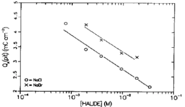
This series of experiments was repeated with vari- ous Cl- and Br- concentrations. In all cases, the value of Q,(pit) showed no systematic dependence on poten- tial. Figure 3 shows a plot of the average value of QA(pit) OS the logarithm of halide ion concentration. The points represent the average of 5 to 31 separate experiments at each concentration; the standard devi- ation of QA(pit) varied from 0.2 to 0.4 mC cm- *. The data show a reasonable linear correlation with the logarithm of the halide ion concentration, and the slopes are similar in the two cases. With increasing [halide], the solution is more aggressive and less anodic charge must pass before pitting begins. Br- is obviously less aggressive than Cl- since the data are shifted to higher values of QA(pit).
-0.4 -0’. 2 d.0 d.2 d.4
POTENTlAL (V olts) vs. Hcy’k$iO,
Fig. 2. The charge passed before the point of divergence of the log i-log r profiles (cf: Fig. 1) vs the anodizing potential for Fe in 9.45 x low3 M NaBr. The open circles represent experiments where pitting attack and no waterline attack was observed on the surface. The half open circles are for experiments where both pitting and waterline attack were
visible on the same sample.
Fig. 3. Average values of Q,(pit) OS the concentration of halide ion present in solution.
The induction time before pit initiation (in a total of 169 experiments) was never greater than 10 s. In addition, pitting was not observed at potentials below
E,,
even if the total charge passed exceeded Q,(pit). This suggests thatE,
can be operationally defined as the minimum potential at which Q,(pit) can be ex- ceeded in less than 10 s. As indicated before[6], this is consistent with the commonly observed linear depen- dence of pitting potential on halide ion con- centration[l-51. The minimum concentration for pit- ting with both Cl and Br was also determined, and corresponds to the lowest concentration in Fig. 3. The value of QA(pit) in both cases is close to 4.25 mC cm-‘, suggesting that pitting will not occur if the charge required exceeds 4.25 mCcm_‘. An anodic charge ~4.25 mCcm_’ cannot be supplied quickly enough to permit pitting to begin, no matter how high the potential.As in previous work, these results suggest that pitting is associated with a particular state of the oxide film, or a particular composition at the surface of the oxide[6]. It should be noted that the results could also be interpreted so that the induction time, z, is the critical parameter in pitting. Certainly, T, which de- pends on [halide] and the anodizing potential, influ- ences the state of development of the oxide. To account for the present results, however, it would be
Halide-induced pitting 231
necessary for z to depend on potential in
zyxwvutsrqponmlkjihgfedcbaZYXWVUTSRQPONMLKJIHGFEDCBA
such a way that the film thickness at time z happens to beindependent of potential. Additionally, this condition would have to prevail at every [halide]. In view of these constraints, the more probable interpretation is that a critical oxide film state (thickness) is necessary for pitting to begin, and is a function only of the [halide]. At the highest concentrations of Cl- used, the value of QA(pit) obtained corresponds to the first appearance of the outer phase on the inner phase[6]. At lower Cl- concentrations, or in solutions contain-
ing the less aggressive
zyxwvutsrqponmlkjihgfedcbaZYXWVUTSRQPONMLKJIHGFEDCBA
Br - ion, more of the outer phase is required to trigger pitting.Experiments starting with a passive film-covered surface
The foregoing results suggest that pitting is associ- ated with a particular stage in the development of the passive film. Previously, it was found that pitting will not occur readily if growth of the oxide film has already passed the critical stage before the sample is exposed to Cl--containing solution[6]. In this section it is shown that this result also applies to Br--induced pitting, and quantitative results are obtained.
In this series 9f experiments, a 2.99 nm thick passive film was formed by anodizing at 0.2 V for 5 min. in pure borate buffer, using the potential step technique. The sample was removed, rinsed and dried, and then immersed into a borate buffer solution containing 9.45 x IO- 3 M NaBr with a cathodic galvanostatic current of 10 ~Acm-’ applied. Reduction was con- tinued for a given length of time before the potential was stepped to 0.2 V. The resulting current transient was compared to that obtained with reduction and anodization in Br - -free borate buffer. Galvanostatic cathodic reduction has been shown to result in a layer- by-layer thinning of the passive film during the first potential arrest[8]. Thus, the amount of the passive oxide film remaining after the cathodic treatment could be varied in a ,systematic manner.
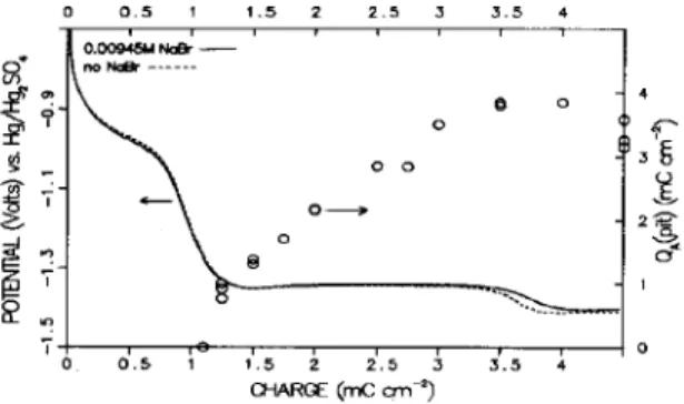
Figure 4 shows the galvanostatic cathodic reduc- tion profiles obtained in the Br--containing and Br-- free borate buffer solutions. There is no significant difference in the two curves. Figure 5 shows the
Fig. 4. Cathodic reduction profiles (10 PA cnmz) of a pre- formed passive film (anodized in Br--free borate buffer) in Br--containing and Br--free borate buffer solution. The circles show the amount of anodic charge passed prior to pitting during a potential step to 0.2 V , after partial cathodic
reduction to the indicated extent.
TlME
(SC)Fig. 5. Log i-log t profiles obtained upon stepping to 0.2 V after various extents of partial cathodic reduction in mC cmm2, indicated by each curve. The solid curves are the current transients observed for Fe in solutions containing 9.45 x 10e3 M NaBr in borate buffer, the dashed curves for Fe in pure borate buffer. The current density scale refers to the top curve, at 0.25 mC cm-’ of cathodic reduction. For clarity, the lower curves have been displaced by factors of ten. The arrows show the points at which the curves can be seen
to diverge.
log i-log
t
profiles obtained at 0.2 V after different extents of cathodic reduction. For reductions of1.1 mCcm_’ or less (see footnote in[6]), no deviation of the two curves was observed, indicating pitting was absent. For greater extents of cathodic reduction, multiple pits were present on the surface, consistent with the deviation of the two curves. Three examples are shown in Fig. 5. Despite the fact that the oxide film remaining on the surface is much thinner at 2.75 mC cm-’ than at 1.75 mCcm_‘, there is no significant change in the induction time prior to pitting. However, there is a significant increase in the charge passed prior to pitting. The results of a number of such experiments are shown in Fig. 4. Clearly, pitting does not occur with a shorter induction time even though the film is thinner, but instead must await the growth of the oxide to a critical state.
CONCLUSIONS
Pitting of Fe by Br- in borate buffer solution occurs when a critical state of the passive oxide film is reached within the first 10 s. of anodizing. This state corre- sponds to a specific thickness of the oxide film, which is dependent on [Br-] but independent of potential. Pitting of Fe is triggered when the passive film devel- ops the outer oxide layer. As the-[Br-] is decreased, more of the outer layer is required before pitting can begin. In addition, pitting is unlikely to occur once the critical state has passed, even if the potential is held above the pitting potential. The implications of these results for the mechanism of pitting will be discussed in detail in a forthcoming publication.
232 J. A. BARDWELL and B. MACDOUGALL
Acknowledgement-The authors would like to thank J. R. Phillips for developing the modifications to the Model 276
4. Z. Szklarska-Smialowska, Pitting Corrosion of Metals,
NACE, Houston (1986).
Interface. 5. H. Bohni, in “Corrosion Mechanisms” (Edited by F. Mansfeld), p. 285, Dekker, New York (1987). 6. J. A. Bardwell and B. MacDougall, J. electrochem. Sm.
REFERENCES 135, 2157 (1988).
7. M. Pourbaix, Atlas of Electrochemical Euuilibria in
1. M. Janik-Czachor, Br. Corros. J. 6, 57 (1971). Aqueous Solutions, p. 180, NACE, Houston (i974). 2. M. Janik-Czachor, Werkstoffe. Korros. 30, 255 (1979). 8. J. Bardwell, B. MacDougall and M. J. Graham, J. electro- 3. H.-H. Strehblow and B. Titze, Corros. Sci., 17,461 (1977). &em. Sot. 135, 413 (1988).