Publisher’s version / Version de l'éditeur:
Vous avez des questions? Nous pouvons vous aider. Pour communiquer directement avec un auteur, consultez la
première page de la revue dans laquelle son article a été publié afin de trouver ses coordonnées. Si vous n’arrivez pas à les repérer, communiquez avec nous à [email protected].
Questions? Contact the NRC Publications Archive team at
[email protected]. If you wish to email the authors directly, please see the first page of the publication for their contact information.
https://publications-cnrc.canada.ca/fra/droits
L’accès à ce site Web et l’utilisation de son contenu sont assujettis aux conditions présentées dans le site LISEZ CES CONDITIONS ATTENTIVEMENT AVANT D’UTILISER CE SITE WEB.
Internal Report (National Research Council of Canada. Institute for Research in
Construction), 1996-09-30
READ THESE TERMS AND CONDITIONS CAREFULLY BEFORE USING THIS WEBSITE. https://nrc-publications.canada.ca/eng/copyright
NRC Publications Archive Record / Notice des Archives des publications du CNRC :
https://nrc-publications.canada.ca/eng/view/object/?id=d9ab7835-70c1-46a4-9ccb-94c6787ccb0b https://publications-cnrc.canada.ca/fra/voir/objet/?id=d9ab7835-70c1-46a4-9ccb-94c6787ccb0b
NRC Publications Archive
Archives des publications du CNRC
For the publisher’s version, please access the DOI link below./ Pour consulter la version de l’éditeur, utilisez le lien DOI ci-dessous.
https://doi.org/10.4224/20338105
Access and use of this website and the material on it are subject to the Terms and Conditions set forth at
Structural Tests of Light Gauge Steel Stud Panels
- - Ser
TH
1R427
no.726
c. 2BLDG
National Research Conseil national Council Canada de recherches Canada Institute for lnstitut d e
Research in recherche en Construction construction
Structural Tests of Light
Gauge Steel Stud Panels
CISTI/ICIST NRC/CNRC I R C S e r R e c e i v e d on: 10-21-96 I n t e r n a l r e p o r tby Charles Kingsley
r n a l r e p o r t ( I n s t i t u t e f ALYSEInternal Report No. 726
Date of Issue: September 30, 1996
This is an internal report of the Institute for Research in Construction. Aithough not
Structural Tests of Light Gauge Steel Stud Panels
Summary of testing programme for wall panels manufactured by
Integrated Building Systems Ltd.
Internal Report No. 726
by:
Charles Kingsley
Institute for Research in Construction
NATIONAL RESEARCH COUNCIL CANADA
Montreal Road, Ottawa, Ontario
KIA
OR6
This report describes the structural tests on a series of light gauge steel stud wall panels carried out by IRC for Integrated Building Systems Limited (IBSL). The testing programme consisted of racking tests and bending tests on 1220 mm x 2920 mm wall panels complete with floor assemblies at the top and bottom, as well as tensile tests on steel samples taken from stud members.
Only a general description of the racking tests and bending tests is presented here. Specific construction details and test results are not included.
This report is prepared and distributed with the agreement of IBSL. If more information is required please contact the following:
Michael Giroux, P.Eng
Vice President, Manufacturing Integrated Building Systems Ltd.
1926 Merivale Rd. Nepean, ON K2G 1E8 Canada Tel.: (613) 727-0123 Fax: (613) 727-0020 E-mail: [email protected]
Racking
Tests
1.1
Introduction
The purpose of the racking tests is to determine the load-deformation properties of different wall constructions when subjected to in-plane loads such as those created by wind and earthquakes. Existing standards such as ASTM E564, ASTM E72, and JIS A1414 can be used to test mdividual wall panels in a uni-directional load pattern. However such tests do not give the true racking resistance of a wall assembly in that, in many types of constructions, the exterior sheathing extends beyond the top and bottom tracks of the wall and over the floor headers. If a sufficient amount of fasteners is used, significant shear forces can be carried by the headers, thus increasing the racking strength of the assembly. Furthermore, unless the racking tests
are
done on wall panels complete with floor assemblies at the top and bottom deficiencies in the assembly, such as the bearing capacity of the C-shape floor joists, may not be properly assessed. Finally the standard tests only call for uni- directional loading. The requirements for these tests, however, were determined to be a bi-directional,a attem.
or push-pull, loadin, p
The tests carried out were therefore based on the aforementioned standards hut with the following modifications:
a) The wall sections were built with a floor assembly at the top and bottom of the wall. b) The load was applied from both ends in a push-pull manner. This established the
behaviour of the specimens under cyclic loading.
This modified racking test was performed on a group of test specimens having different constructions. To determine the effect of various configurations on the racking strength of the steel stud walls, the following components were varied:
Orientation of exterior sheathing (parallel or perpendicular to studs) and locations of sheathing joints.
Sheathing material (1 1 mrn OSB, 13 mm plywood, 20 gauge sheet steel, 12.7 mm gypsum board).
.
Size of studs and web stiffeners (14 gauge, 18 gauge, and 18-gauge box stud). Fastener types (nails, #8 or #10 screws) and spacing.1.2
Test
specimens
All test specimens were manufactured and supplied by IBSL. Eighteen tests were canied out on 1220 mm x 2920 mm test specimens.
The test specimens consisted of a 1220 mm x 2460 mm steel stud wall with 200 mm deep floor assemblies at the top and bottom, with all framing details done in accordance to the Ontario Building Code (OBC).
The wall sections were clad with sheathing on one side only. The different sheathing configurations used are shown in Fig. 1 and are as follows:
a) Sheathing parallel to studs: one 1220mm x 2440 mm OSB sheet with long direction parallel to studs and two smaller pieces located over the floor headers. Joints perpendicular to the studs were located at the floor and ceiling levels. Each comer was reinforced with 50 mm
wide x 500
mm
long x l&gauge steel straps. Sheathing was placed on outside face of wall.b) Sheathing perpendicular to studs: three pieces of OSB or plywood sheets with long
direction perpendicular to studs and extending over the floor headers. Joints perpendicular to the studs are at about ' I 3 and '1, of the specimen height and are reinforced with
150 mm wide x 20-gauge sheet steel. Sheathing was placed on outside face of wall.
c)
Drywall:
two pieces of 12.7 mm drywall stopping at the top and bottom floor tracks with one joint perpendicular to the studs at mid-height. Joint was reinforced with drywall tape and compound. Sheathing was placed on inside face of wall.d) Steel sheathing: three pieces of 2@gauge sheet steel exfinding over the floor headers, with
overlapping joints perpendicular to studs at about '1, and '13 height. Sheathing was placed on
outside face of wall.
The floor assemblies consisted of floor joists connected to a steel track (header) and covered with 16 mm OSB flooring. Web stiffeners were also placed next to the joists and were used to transmit the loads from the studs to the test frame base. These were required to prevent buckling of the floor joists during the racking tests.
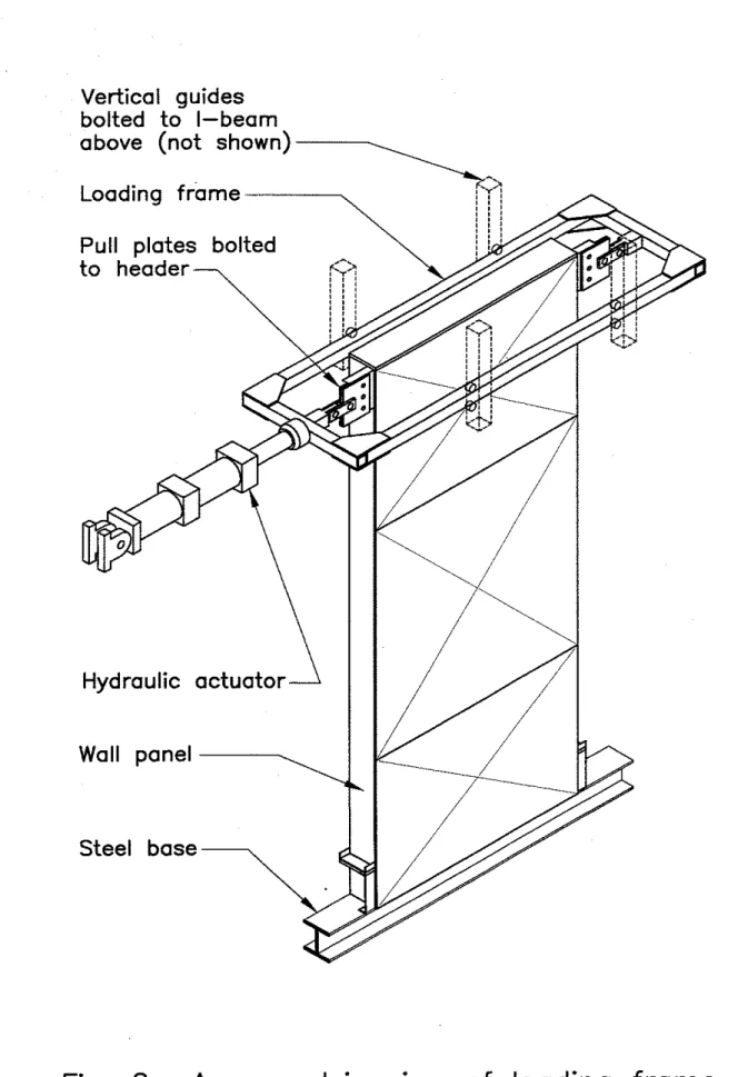
To transmit the load from the loading frame to the test specimen, the top floor header was extended by 150
mrn
on both ends of the wall and pull plates were bolted to it as shown in Fig. 2.All the test specimens were fabricated with material having the following specifications: 41.3 mm x 152.4 mm studs for wall studs
41.3 mm x 101.6 mm studs for web stiffeners 41.3 mm x 203.2 mm studs for floor joists
30.0 mm x 152.4 mm tracks for top and bottom wall floor tracks 30.0 mm x 203.2 mm macks for floor headers
The above components were of different gauges, depending on the test specimen. Standard metric equivalents for the different gauges are as follows:
20-gauge: 1.00 mm +. 0.10 mm
1Bgauge: 1.31mm?O.l3mm 14-gauge: 1.99
mm
+. 0.15 mmOSB: -All OSB (oriented strand board) sheathing used for wall cladding conformed to CSA standards CSA 0325.0 and CSA 0437.0. Sheets were 1 1.1 mm x 1220 mm x 2440
mm,
grade 0 2 (aligned face and random core).Plywood:
-
Plywood sheet was 12.7 mm x 1220mm
x 2440 nu& 4-ply plywood with two outside plies in long direction and two inside plies in short direction.Drywall:
-
Standard 12.7mm
x 1220 m m x 2440 mm drywall sheets were used.Nails:
-All nails were coil collated steel pins for use with a pneumatic nailer. Shanks were 2.5mm
in diameter with spiraled grooves and ballistic point. Nail heads were 6.5 mm in diameter.Screws:
-
Drywall screws were #6 x 32mm
type 'S' point drywall screws conforming to ASTM C1002 requirements. All other screws were self-drilling screws ('SD' point) conforming to ASTM C954 requirements.1.3
Apparatus
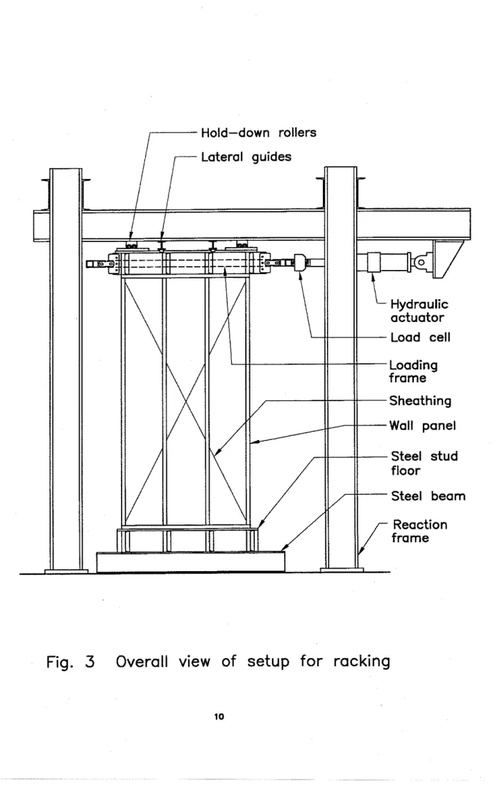
Reaction fmnre:
-
The reaction frame shown in Fig. 3 was used for the racking tests. It consisted of four heavy-steel columns bolted to a concrete strong-floor. C-channels are bolted to these columns and are used to support a heavy-steel I-beam which in turn is used to support hydraulic actuator, tbe lateral guides and the hold-down rollers.Hydraulic actuator:
-
A 100.kN hydraulic actuator with a built-in load cell was used. With the help of an electronic controller and appropriate software, the tests were performed under displacement control.Loadframe:
-
To prevent buckling of the header in the push-pull mode, the load was alternately applied from both ends using the loading frame shown in Figures 2 and 3. The loading frame was guided in the vertical and lateral directions by ball bearing track rollers on the four comers of the frame.Hold-down rollers:
-
To prevent uplift in the wall, hold-down rollers were employed. These were located above the top floor assembly, on both ends of the wall. A steel plate was placed between the floor assembly and the roller to distribute the load to the web stiffeners.Lateral guides: - To maintain the wall in the plane of loading, lateral guides with ball-bearing track rollers as shown in Fig. 3 were used.
Floor beam: - The bottom of the test specimens were bolted to an 'I' beam with at least ten 6.35 mm diameter bolts along the bottom flange of the floor header. The 'I' beam, reinforced with web stiffeners aligned with the studs of the test specimens, was fixed to the concrete strong floor.
Load measurements: - A 100-kN calibrated load cell attached to the hydraulic actuator was used for load measurements.
Deformation measurements:
-
Calibrated extensometers were used to measure all displacements. All the extensometers were mounted to a fixed base, independent of the reaction frame. Figure 4 shows the location of these extensometers whereas the following list explains the location and function of each extensometer:.
Extensometers D, and D6 measured the horizontal displacement at the top of the wall section..
Extensometers D2 and D5 measured the horizontal displacement (or slip) at the bottom of the wall section..
Extensometers D3 and D4 measured the vertical displacement of the sheathing at the bottom of the wall section..
Extensometers D, and DH measured the vertical displacement of the sheathing at the top of the wall section..
Extensometers D9 and Dlo,
placed diagonally across the face of the sheathing, measured the shear deformation of that sheathing..
Extensometers Dl, and Dlz measured the vertical displacement of the bottom track. Data acquisition: - All data from the extensometers and the load cell was acquired by a computerized data acquisition system.1.4
Loading sequence
All the test specimens were loaded in a quasi-static cyclic manner using a fixed
displacement rate as shown in Fig. 5. The loading regime was as follows: two cycles to each of the following net horizontal displacements (Dl -D2) : +8 IIXQ -8
mm, c12
mm,-12 mm, +24 mm,
-24 mm;
and one cycle to +48mm
and-48 mm.
The specimen was then loaded to failure in theP+
direction. Failure was defined as rupture or local buckling of one of the main structural members or the shear failure of the sheathing material.1.5
Observations
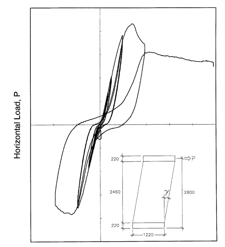
By using this loading regime, a load-deformation curve similar to that shown in Fig. 6 is obtained. This curve shows the horizontal load, P, versus the net shear deformation, y. The net shear deformation is obtained by subtracting the rigid body rotation of the wall from the total horizontal
deformation. The hysteresis loops show the degradation in stiffness which can be expected during cyclic loading.
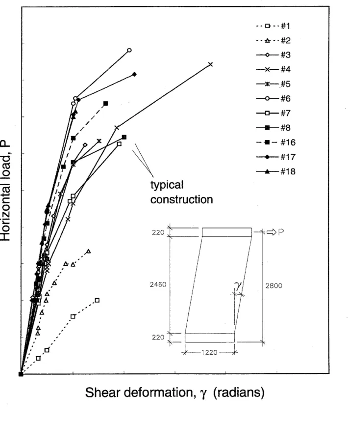
From the load-deformation curve of each wall panel, the chart shown in Fig. 7 is obtained. Each curve in this chart represents a specific wall specimen and is derived by taking key values from the failure envelope of each load-deformation curve. This chart is used to show the relative performance of the wall panels.
Bending Tests
2.1
Introduction
Bending tests were carried out in order to determine the resistance of the steel stud walls to lateral loads such as those caused by wind. A simplified method in which the specimen is tested on its side with two line loads at a distance of one quarter of the span from the supports is commonly used. This test is described in standards ASTM E72 and JIS A1414. These test standards were used by IBSL and their consultants to develop similar tests in which top and bottom floor assemblies are included. The specimens were also to be loaded in a static mode to failure, without any cycling.
2.2
Test Specimen
All test specimens were manufactured and supplied by IBSL and are similar in construction to those described in section 1.2 of this report. A series of twelve tests where initially planned on 1220 mm x 2920 mm test specimens. However, at the request of the client, only three tests were carried out.
2.3
Apparatus
Reaction frame:
-
The same reaction frame as for the racking tests was used for the bending tests.H y d r d i c actuator:
-
A 100-lcN hydraulic actuator with a built-in load cell was used. With thehelp of an electronic controller and appropriate software, the tests were performed under displacement control.
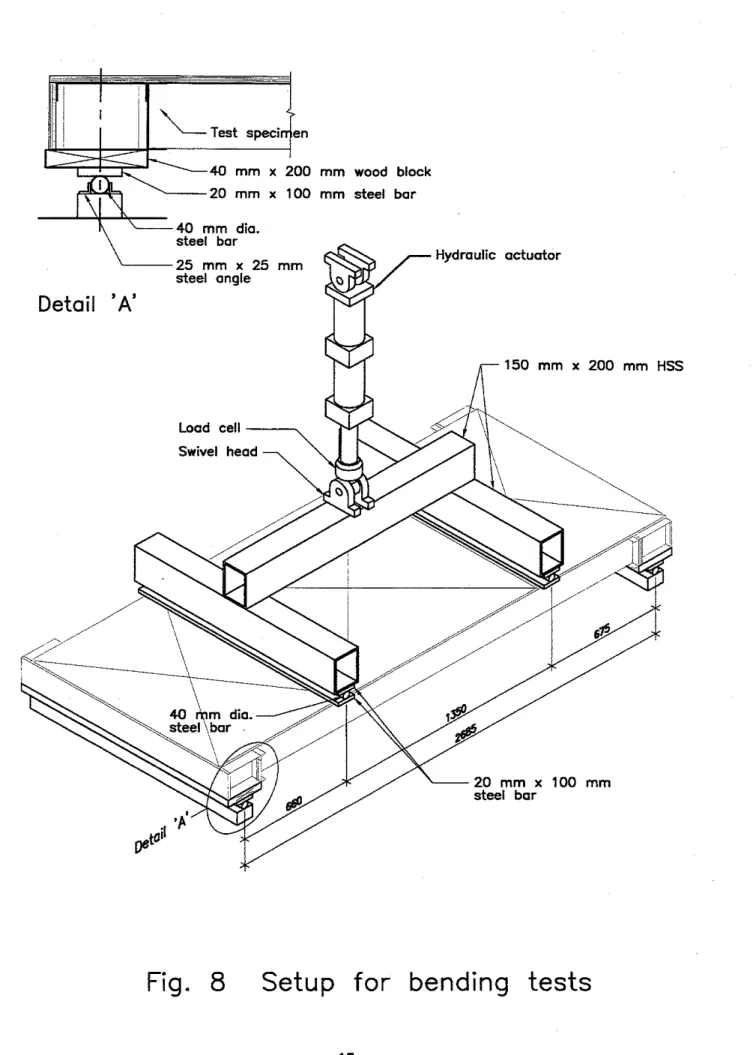
Load frame:
-
An'H'
frame, illustrated in Fig. 8, comprised of three 6.35mm
x 150 mm x200
mm
hollow structural sections (HSS) was used to transmit the point load of the actuator into two line loads at one quarter points of the mid-span. Under each HSS members were a 40mm
diameter steel rod sandwiched between two 20 mm x 100 mm steel bars.Reaction points:
-
The reaction points for the test specimens were composed of a 40 mm x200 mm wood block on top of a 20
mm
x 100 mm steel bar and 40 mm diameter steel rod.Load measurements:
-
A 100-kN calibrated load cell was used for load measurements.Defonnntion measurements: - Calibrated extensometers were used to measure all
Figure 9 shows the location of these extensometers whereas the following list explains the location and function of each extensometer:
.
Extensometers Da and D5 measured the vertical deflection at the mid-span location of the test specimens and were placed on the OSB sheathing..
Extensometers Dl, D3, D4, and D6measured the vertical deflection at the loading points. They were connected to100 mm
x 100 mm steel plates clamped to the loading bars..
ExtensometersD7,
Dl,,, DI1, and Dl4 measured the vertical deflection at the top and bottom wall track of the wall section. They were located on the flange of the tracks..
Extensometers Dg, Dg, DIZ, and Dl, measured the vertical deflection at the centreline of the floor assemblies. They were located on the web of the header.Data acquisition:
-
All data from the extensometers and the load cell was acquired by a computerized data acquisition system.2.4
Loading sequence
All test specimens were loaded in a static manner using a fixed displacement rate until failure. Failure was defined as bending failure or local cxushing of one of the main structural members or of shear failure of the fasteners at the floorlwall interface.
2.5
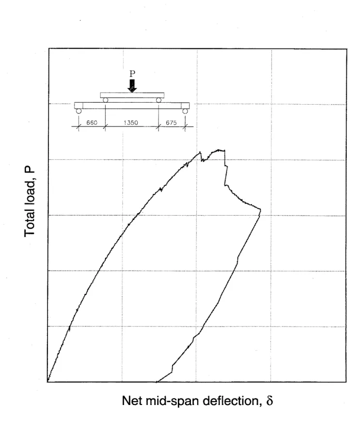
Results and Observations
A typical load-deflection curve for the bending tests is shown in Fig. 10. This curve shows the applied load, P, versus the net mid-span deflection,
6.
As the deflection increases, there is a gradual decrease in stiffness up to the failure of the assembly.Fig.
1
Different sheathing configuration used
f o r racking tests
Vertical guides
bolted t o I-beam
above (not shown)
Pull plates bolted
Hydraulic actuator
Fig.
2
Axonometric view of loading frame
i
Hold-down rollers
/
,--
Lateral suides
Fig. 4
Location of extensometers f o r
racking tests
Shear deformation,
y
Fig.
6
Typical load-deformation curve for
racking test on
IBSL
test specimen
construction
Shear deformation,
y
(radians)
Fig.
7
Shear deformations for various
panel configurations
Test speciien 40 mm x 200 mm wood block 2 0 mm x 100 mm steel bar -40 mm dia. steel bar Hydraulic actuator 2 5 mm x 25 mrn steel angle