Custom Mechanisms for Tunable Material
Deposition
by
Jared Smith Laucks
B.Arch., Philadelphia University (2008)
MASSACHUSETS INGTffffTE OF TECHNOLOGy
JUL 1 4 2014
LIBRARIES
Submitted to the Program in Media Arts and Sciences, School of
Architecture and Planning
in partial fulfillment of the requirements for the degree of
Master of Science in Media Arts and Sciences
at the
MASSACHUSETTS INSTITUTE OF TECHNOLOGY
June 2014
@
Massachusetts Institute of Technology 2014. All rights reserved.
Signature redacted
A uthor ...
Program in Media Arts and Sci ce
Certified by
's, Scholfof rchitecture and
Planning
'4 MNA1894Signature redacted
Pr4f.
Accepted by
Neri Ox nan
Assistant Professor, Program in Media Arts and Sciences
Director, Mediated Matter
Supervisor
Signature redacted
<-:V ht7T htricia Maes
Associate Academic Head, Program in Media Arts and Sciences
Custom Mechanisms for Tunable Material Deposition
by
Jared Smith Laucks
Submitted to the Program in Media Arts and Sciences, School of Architecture and Planning
on May 18, 2014, in partial fulfillment of the requirements for the degree of
Master of Science in Media Arts and Sciences
Abstract
Digital fabrication tools, specifically additive manufacturing systems, have consis-tently advanced in efficiencies such as print speed, gantry size, material cost and ease of use. However most of these systems remain limited in their ability to enable au-tomated mixing and extrusion of multiple materials with variable properties on large scales. This thesis focuses on the first steps of realizing this enabling technology by operating across two distinct trajectories. The first aims at digitally controlling preci-sion path placement of material with high levels of tunability through analog mixing, while the second explores do-it-yourself tool customization, compactness, portability and the possibility of fabrication node-to-node communication. Inspired by the silk-worm's ability to spin highly sophisticated and tunable material architectures, the aim of this thesis is to develop an enabling technology for digital fabrication requir-ing high levels of material tunability in product and architectural scales. Specifically,
I designed, developed, built and evaluated an array of six unique customizable and
compact deposition heads for tunable material properties. Amongst those tools is a freeform extrusion head for tunable geometry without the need for auxiliary support structure; a fast thread deposition head and a fiber winding head for tunable com-pressive and tensile strength respectively; a portable cable-suspended paste droplet extrusion head for tunable drop size of paste material; and a chitosan gel extrusion head for tunable plasticity using biomaterials. Operating across the two trajectories of tunability and portability, this thesis argues that highly tunable, compact and portable extrusion heads developed within a Fab Lab environment can support vari-able property printing of one or more materials outside of commercial based systems. This capability will in the future enable the digital fabrication of larger-scale pro-totypes, sustainable products and architectural structures inspired by nature in Fab Lab settings.
Thesis Supervisor: Prof. Neri Oxman
Title: Assistant Professor, Program in Media Arts and Sciences Director, Mediated Matter
Custom Mechanisms for Tunable Material Deposition
by
Jared Smith Laucks
The following people served as readers for this thesis:
Signature redacted
Professor Neil Gershenfeld.. ...
Director, The Center for Bits and Atoms Professor of Media Arts and Sciences
Signature redacted
Professor Joe Paradiso.... ...
(7
Director, Responsive EnvironmentsAcknowledgments
Firstly, I would like to thank professors and advisors who have mentored me at the
Philadelphia University College of Architecture - Chris Kircher, Simon Koumjian,
Christian Jordan, Jane Cespuglio and Susan Frosten - without whom I would not
have been educated in an environment where I could test the boundaries of what the definition of Architecture is. I would also like to thank my colleagues whose work and support has always inspired and pushed me forward through the years: Skylar
Tibbits, Brandon Kruysman and Jon Proto - thank you for the continued dialog
through these years!
Secondly, I would like to thank the Media Lab staff and community without whom the time I have spent here would not have been made possible. Thank you to
all the lab members who loaned a hand and greeted our team for the many weeks of constructing the Silk Pavilion in the lobby of E14. Thank you Greg Tucker and Kevin Davis for helping us jump through all of the hoops required to take on a large-scale project.
A special thanks to the CBA and to the "How to Make Almost Anything" team for
inspiring some of the first extrusion head designs for the Silk Pavilion and supporting our many hours in the shop. Also, a special than you to James Weaver, a friend, imaging extraordinaire and force to reckoned with. Also, to Javier Fernndez and Don Special of the Wyss Institute at Harvard for their close collaboration on the chitosan material development and experiments.
Gratitude also goes to my Mediated Matter colleagues who, without the many meetings, discussions, suggestions, and support, my projects at the lab would not have been realized: thank you Markus Kayser, Carlos David Gonzalez Uribe, Jorge Duro-Royo and Laia Mogas-Soldevila! A special thanks goes to our group director Dr. Neri Oxman for her constant positive attitude, energy, feedback and encouragement through each and every step of the way.
I would also like to thank the readers of this thesis, Professor Joseph Paradiso,
Mostly, I would like to thank my parents. I thank my father for teaching me that things can break and come apart; some can be fixed, and new things can be created. Without these fundamentals I would not have gotten to this point and would not had the urge to keep breaking and making things every day. I thank my mother for
Chapter 1
Introduction
To date, digital fabrication systems have typically functioned as manipulators of pre-defined materials. This has typically been the case in subtractive capacities, but also more recently in additive manufacturing systems. With the introduction of Com-puter Numerically Controlled (CNC) machining in the 1950's [Reintjes, 1991] digital computing became associated with physical machine control. However, the digital revolution that followed did little to integrate between Computer Science and the physical sciences. Furthermore, given that the control of motors and the various elements of the tooling process remain an analog process, the notion of "digital" must be challenged in the context of physical matter and the design of hardware [Gershenfeld, 2005].
Most recently, Three Dimensional Printing (3DP) has evolved to provide increased precision control over material placement by digitally controlling droplet position in space via the computer. However, the mode of droplet placement is still an ana-log process [Gershenfeld, 2005]. Some of the most innovative research done in this area comes from the Center for Bits and Atoms (MIT) and the Creative Machines Lab (Cornell University). Under the umbrella of "Digital Materials", research at the CBA has previously presented analogs to atoms and bonds that enable the al-location of individual elements within a physical structure "much like the encoding of a data structure" [Popescu et al., b]. In this work, experimental measurements are presented that show how this control is used to tune both mechanical and
elec-tronic material properties and, in addition, it demonstrates how to implement the generation of assembled functional structures [Ibid]. This research challenges cur-rent additive fabrication approaches by considering digital materials that are de-fined as discrete and non-continuous physical voxels referred to as Digital Materi-als [Gershenfeld, 2005, Popescu et al., b, Popescu et al., a, Hiller and Lipson, 2007, Hiller and Lipson, 2008]. While this thesis does not aim at replicating digital mate-rials, it builds off of the notion that this approach enables precise control of property variation in a predictable and logical way without distinguishing between the digital and physical domains. The aim of this thesis is to demonstrate a deeper understanding of digital control of continuous materials through analog mixing of different material properties in a non-commercialized format, supporting a fab-lab like environment.
My work is inspired and informed by the "maker movement" which facilitates the
spirit of tool making, that of designing computers that do not control other tools but rather computers that are tools in themselves, and, eventually building "Machines that make Machines" [Gershenfeld, 2005, Gershenfeld, 2008, Gershenfeld, 2009].
In contrast to digital materials, the state of the art in Digital Architecture focuses on fabrication as assemblies of prefabricated low-level components that are materially homogeneous [Oxman and Mitchell, 2010]. The established approach of constructing pre-manufactured building components stands in contrast to the potential of digital fabrication systems to deliver highly customized structural and material forms. In the biological world, however, there exist various organisms able to deposit highly sophis-ticated material architectures to construct large-scale and highly efficient structures.
The Bombyx mori silkworm, for example, varies the chemical composition of its silk according to the desired function. In this respect the silkworm can be considered a portable organism able to extrude highly tunable material architectures
[Oxman et al., 2012a]. Inspired by the silkworm, this thesis sets forth a framework for
the classification of digital fabrication systems - specifically, additive manufacturing
-along two main axes: the first axis is that of material tunability ranging from "prim-itive" non-tunable and homogeneous material architectures to sophisticated tunable and heterogeneous ones. While the ability to achieve and control Digital Materials as
per CBAs definition, where parts can potentially code for the structure of the build-ing, is not yet implemented, my research in this context points towards this capability and its promise. Inspired by the notion of the Fab Lab, the second axis is that of tool compactness and portability ranging from stationary non-portable tools (like a typical 3D printer) to highly compact and portable systems (like the silkworm itself).
M Material property Tunability Z Silkworm Silk Swa rm (Termites) 3D Printing Process
Compact & Communicative
h Portability /
Compactness
Figure 1-1: Research framework: at the core of this thesis is the assumption that ad-ditive manufacturing systems will advance along two trajectories. The first is material sophistication, through tunable material properties and the ability to co-extrude fiber composites. The second is compactness and portability of fabrication devices. This matrix provides for a research framework within which the designs of 6 extrusion heads is implemented and tested.
The thesis is organized in two main chapters. The first (Chapter 2: Compact & Tunable Material Deposition in Nature) reviews the method by which the silkworm extrudes silk and what are the parameters that govern the geometrical and physical tunability of the fiber on various scales. The second (Chapter 3: Compact & Tunable
0
-c .5
C 0
Material Deposition in Digital Fabrication) offers an array of compact extrusion heads that I designed, developed and evaluated in the context of specific design projects. The following sub-sections (1.1-1.6) offer a short description of the main chapters, their content and structure.
1.1
Compact & Tunable Material Deposition in
Nature
The formation of highly tunable non-woven fiber architecture generated by the
Bom-byx mori silkworm is investigated as a case study for tunable extrusion in the
bio-logical world. Beyond the analogy of the silkworm as a highly portable organism for tunable material deposition, this section also suggests that the silkworm's method of depositing silk can provide for a a computational approach for shape and material optimization as well as, potentially, material fabrication. Biological case studies are presented and a design approach for the use of silkworms as entities that can compute and fabrication fibrous material organization is given in the context of an architec-tural design installation. The chapter demonstrates that in the absence of vertical axes the silkworm can spin flat silk patches of variable shape and density and there-fore, the spinning behavior can be template and tuned by providing the silkworm with topographical constraints. Furthermore, experiments presented in this section sug-gest sufficient correlation between topographical surface features, spinning geometry and fiber density. The chapter represents a scalable approach for optimization-driven fiber-based structural design and fabrication, and suggests a biology-driven strat-egy for material computation and deposition towards possible applications in digital fabrication.
1.2
Compact Freeform Extruder Head for Tunable
Geometry
Freeform 3D Printing: Towards a Sustainable Approach to Additive Manufacturing
This section is the first of a series of sub-sections to be included under chapter
3:"Compact & Tunable Material Deposition in Digital Fabrication". This section
presents a compact freeform extruder head for tunable geometry.
Most additive manufacturing technologies such as 3D printings utilize support materials in the fabrication process. Beyond the technical challenges of support re-moval, these materials are wasteful increasing fabrication and processing time while impacting quality. This section presents "Freeform Printing", a novel design approach for 3D printing without additional auxiliary structures. A 6-axis KUKA robotic arm is repurposed as a 3D printing platform onto which custom-designed thermoplastic extruders are attached. Freeform extrusion using a round nozzle attached to an active air-cooling unit, which solidifies the material upon extrusion is demonstrated. In ad-dition, a method for printing geometrically complex structures using a multi-strand extrusion nozzle is presented. The experiments presented in this section, combined with their evaluation and analysis, provide proof-of-concept for Freeform Printing without support materials. They represent a sustainable approach to additive man-ufacturing and digital fabrication at large, and point towards new possible directions in sustainable manufacturing.
1.3
Compact Fiber-pulling Head & Fast-thread
Deposition Head for Tunable Fibrous
Compressive Strength
Robotically Controlled Fiber-based Manufacturing as Case Study for Biomimetic Digital Fabrication
This section presents a compact fiber-pulling head as well as a fast-thread head for tunable fibrous compressive strength.
The research explores the process of silk deposition generated by the silkworm
Bombyx mort and proposes a novel fiber-based digital fabrication approach inspired
by its biological counterpart. I review a suite of analytical methods used to observe
and describe fiber-based constructions across multiple length-scales. Translational research from biology to digital fabrication is implemented by emulation in the de-sign of fiber-based digital fabrication techniques utilizing a KUKA robotic arm as a material deposition platform. The methods by which the silkworm Bombyx mort constructs its cocoon and scafolding structure is discussed, and possible applications of fiber-based digital fabrication in the construction of an architectural pavilion as a case study are speculated upon.
1.4
Compact CNC Fiber Placement Head for
Tunable Tensile Strength
Silk Pavilion: A case study in Fiber-based Digital Fabrication
This section presents a CNC fiber placement head for tunable tensile strength, designed and deployed for the Silk Pavilion.
The Silk Pavilion explores the relationship between digital and biological fiber-based fabrication on an architectural scale. Its primary structure is comprised of
26 silk-threaded polygonal panels laid down by a CNC (Computer-Numerically
Con-trolled) machine. Inspired by the silkworms ability to generate a 3D cocoon out of a single multi-property silk filament, the Pavilion's overall geometry was created using an algorithm that assigns a single continuous thread across patches, providing func-tional density gradients informed by environmental constraints such as light and heat. Overall density variation was informed by deploying the Bombyx mort silkworm as a biological multi-axis multi-material 3D "printer" in the creation of a secondary fiber structure. 6,500 silkworms were positioned on the scaffold spinning flat non-woven
silk patches locally reinforcing the CNC-deposited silk structure. The section provides a review of basic research into the silkworms spinning behavior, material and struc-tural characterization, computational simulation and fabrication strategy devised for the full-scale construction of the Pavilion. I conclude with potential applications for fiber-based digital fabrication in large scale that implement some of the insight gained from biologically-inspired fabrication.
1.5
Portable Paste-Drop Deposition Head for
Tunable Compressive Strength
This section presents a portable paste-drop deposition head for tunable compressive strength. The head was designed developed as part of a cable-suspended robotic
3D printing platform. The aim of the project was to achieve high levels of material
tunability using a compact and portable single-node fabrication system, and high levels of communication using a multi-node fabrication system, respectively. The extrusions unit is inspired by the Skycam technology only instead of a camera I
developed and integrated a paste drop deposition head.
1.6
Compact Chitosan Deposition Head for
Tunable Plasticity
This section presents work-in-progress for a chitosan deposition head for tunable plasticity. The compact chitosan deposition head was designed to achieve highly tunable fibrous material deposition for deployment under the water and controlled spatial deformation over time. My tool was developed in the context of current group work for the construction of an underwater Pavilion designed to immobilize clean seawater by deploying large-scale soft biodegradable chitosan gel structures that take on their morphology when submerged within the ocean's surface. The extrusion head was designed as a two-chamber head containing chitosan (semi-viscous material) while
a second chamber would enable storage and dispensing of granular material based upon the filler requirements for tunable plastic properties.
Chapter 2
Compact & Tunable Material
Deposition in Nature
Biological Computation for Digital Design and Fabrication
2.1
Introduction
2.1.1
Form-generation and Optimization in Nature
Biological systems can be characterized as entities that "compute" and "fabricate" material organization according to external performance criteria. Bone tissue, for in-stance, alters between states of compact tissue and spongy tissue as a function of the
applied structural load and the requirement for blood circulation[Oxman and Mitchell, 2010]. Similarly, spider silk alters its mechanical properties as a function of its use:
spi-ral silk is used for capturing prey while cocoon silk is used for protective egg sacs [Nova et al., 2010]. The range of variation in material distribution and physical prop-erties is typically defined by the extreme set of external conditions acting as the "en-vironment". The system's overall form and mechanical properties are derived from processes of shape and material optimization respectively, maximizing compatibility between the system's innate material properties, its external environment and its desired performance criteria [Oxman et al., 2012c]. As a result natural systems
typi-cally exhibit high levels of integration between shape, structure and material making Natures designs highly efficient and effective forms of "computation".
Furthermore, going beyond the already absent examples of complex materials that insects and animal in nature secrete for their various purposes, speculative fiction has often extrapolated this capability to interesting and intriguing new heights eg. [Forward, 1996].
2.1.2
Form-generation and Optimization in Digital Design
Unlike the biological world in which there exist high levels of integration between shape and material distribution[Benyus, 2009], digital design protocols are typically divided into processes of form-generation and processes of performance-based opti-mization, the former being a precondition for the latter [Oxman and Mitchell, 2010]. Finite element methods for example, implemented in order to optimize shape, mate-rial properties and distribution, are applied only after the form has been generated
[Brenner and Carstensen, 2004]. Another distinction between biological and digital optimization is the ability in the Natural world to produce combinations of property and morphological variation of isotropic structures
[Benyus, 2009, Omenetto and Kaplan, 2010, Oxman et al., 2012a, Oxman et al., 2012b]. In digital design, optimization processes are typically divorced from material organiza-tion, since most fabrication materials are anisotropic in property [Oxman et al., 2012c].
Given the advantages of biological shape-generation and optimization protocols, can processes of biological optimization be used to inform and compute desired structural and environmental performance of man-made structures?
Given almost any 3D entity, a broad suite of techniques in computational design exists that supports form-generation and optimization processes within parametric environments [Kolarvevic and Klinger, 2008]. Examples of such techniques include particle systems, multi-agent systems, network analysis, and finite element methods [Haroun and Hanna, 2004]. Replacing such computational processes with biological ones allows informing shape-generation processes as well as spatial material
organi-2.2
Background
2.2.1
Biological Computation for Digital Design &
Fabrication
Numerous forms in Nature achieve their shape and structure through local optima processes, as material organization and composition are informed by structural and environmental stimuli [Brady, 1985, Colorni et al., 1996]. Consider the optimal shape of tree branches or animal tissue morphology. These shapes and their material com-position express an effective use of information as well as an efficient thermodynamic operation for an environment-interacting system. These processes can be used both as models by which to explain and predict other natural processes but also as compu-tations in their own right[Brady, 1985, Colorni et al., 1996, Shaffer and Small, 1997]. Research into the use of biological processes as forms of computation the can in-form design generation are found for example in the use of slime molds in order to model real-world infrastructural networks[Tero et al., 2010]. Here problems are de-scribed as instances of the distributed growth dynamics of the slime mold resulting in the encoding of a general linear programming (LP) language. Results prove that the model converges to the optimal solutions of the LP [Ibid.]. Captured in a biologi-cally inspired mathematical computation, this research can potentially guide network construction in other domains.
2.2.2 The Silk Pavilion - General Background
Inspired by optimization processes in Nature like that of the slime mold described above, the Silk Pavilion is an architectural structure fabricated by digital fabrica-tion technologies combined with the deployment of live silkworms. It explored the relationship between digital and biological fabrication on product and architectural scales. The primary structure is created of 26 polygonal panels made of silk threads laid down by a CNC (Computer-Numerically Controlled) machine. Inspired by the silkworm's ability to generate a 3D cocoon out of a single multi-property silk thread
(1km
in length), the overall geometry of the pavilion is created using an algorithm that assigns a single continuous thread across patches, providing various degrees of density. Overall density variation is informed by the silkworm itself deployed as a semi-stochastic biological "printer" in the creation of the secondary structure. A swarm of 6500 silkworms were positioned at the bottom rim of the scaffold spinning flat non-woven silk patches as they fill the gaps across the CNC deposited silk fibers. Following their pupation stage the silkworms are removed. Resulting moths can pro-duce 1.5 million eggs with the potential of constructing up to 250 additional pavilions(Figure 2-1).
Figure 2-1: Composite image of completed Silk Pavilion installation and Bombyx
mori silkworms spinning on the CNC fabricated super-structure.
Affected by spatial and environmental conditions such as geometrical density gravity[Chen et al., 2012], variation in natural light and heat the silkworms were found to migrate to denser and darker areas. Desired light effects informed variations in material organization across the surface area of the structure. A season-specific sun path diagram mapping solar trajectories in the space dictated the location, size and density of apertures within the structure in order to lock in rays of natural light entering the pavilion from South and East elevations. The central oculus is located against the East elevation and may be used as a sun-clock.
The construction process of the Silk Pavilion was inspired by basic research exper-iments reported herein that informed processes of modeling, analysis and fabrication. This section reports upon experimental work considering biological forms of compu-tation for digital design modeling, analysis and fabrication. Specifically, we explored the formation of non-woven fiber structures generated by the Bombyx mori silkworm as a computational schema for determining shape and material optimization of fiber-based surface structures particularly because it is the most common species found for silk production when compared to the various wild species[Chen et al., 2012]. This biological form of "computation" can potentially exclude the need for Finite Element methods.
2.3
Aims and Goals
Fiber-based structures are ubiquitous in both architectural and biological systems. Robust structural performance involves the balancing of force-and-response in order to achieve material morphologies that are structurally efficient and environmentally effective [Oxman et al., 2012c]. Typically this process involves a step-wise process in-cluding computational modeling, finite-element analysis and digital fabrication. Bi-ological fiber-based structures such as the silkworm's cocoon however may provide for the unification of these three media through the use of the silkworm's path as an optimization "tool-path" and a fabrication "technology". The guiding assumption here is that the silkworm's ability to generate fiber structures with varying degrees of density based on its environment has been perfected through evolutionary pressure. It is also assumed that the cocoon is an optimal structure which itself is based on the idea that optimization-seeking processes are omnipresent in Nature. Having been developed without top-down control this case may represent a scalable approach for fiber-based structural design based on optimization. Our main goal is to determine whether these structures are likely to yield reasonably efficient solutions to combi-natorial optimization challenges such as load informed fiber-density distribution in membrane structure.
2.4
Methodology and Experimental Set-up
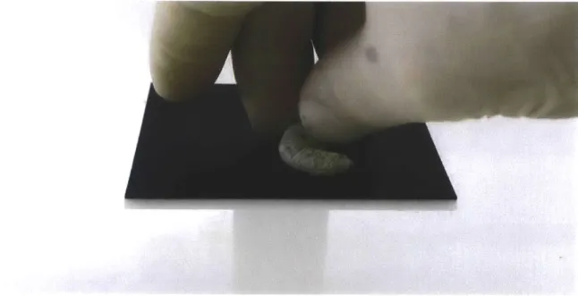
The experimental set-up consisted of a series of surface patches measuring 8OX80mm in surface area with varying sectional configurations. A live silkworm was positioned on top of the surface and left to spin. It is hypothesized that spinning configurations and the fiber density distribution would vary according to the morphological features of the hosting "environment" (Figure 2-2).
Figure 2-2: Placement of a Bombyx mori silkworm on top of a flat surface-spinning platform.
2.4.1
Initial Experimentation to Determine Fiber-Density
Variation in Flat-spun Silk
The first experiment consisted of a flat surface patch with no additional surface fea-tures. The silkworm appeared to have spun a flat silk patch instead of the anticipated
3-D cocoon structure. This was due to the lack of a physical vertical pole/axis against
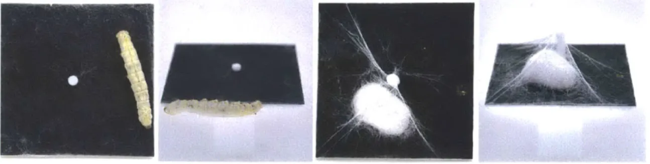
which the silkworm would otherwise construct its cocoon.The experiment confirmed that the Bombyx mori silkworm would spin silk as a flat patch in the absence of vertical surface features (Figure 2-3).
Figure 2-3: A Bombyx mori silkworm completing the deposition of approximately 1km of flat-spun silk. The research confirms that given the absence of a vertical axis the silkworm will spin a flat silk patch
2.4.2
The Dice Series
Following, a central vertical axis of varying heights was introduced to determine (1) at which height point would the 3D cocoon structure emerge, and (2) how might fiber distribution be affected by the relative location of the vertical axis and its height. A family of tent-like structures consisting of a rectangular surface patch with a single
Figure 2-4: Comparison of two 1-dice configurations with a 3mm and a 21mm vertical axis illustrating the difference between flat spinning (sufficiently short vertical axis) and a cocoon spinning (sufficiently long vertical axis).
Varying axes heights of 3mm, 6mm, 9mm, 12mm, 15mm, 18mm, 21mm, 24mm, and 27mm were implemented (Figure 2-5).
,,EEEE,
Figure 2-5: Series of one-dice platforms ranging in vertical axis height from 3mm to 27mm each with 3mm increments.
The experiments demonstrated the following: (1) a 3D cocoon structure emerged only at a sectional height of 21mm height below which a tent-like structure in the form of a rectangular pyramid was spun. Given the dimensions of the natural cocoon
it was assumed that a minimum height of - 21mm accounting for the longitudinal
axis of the cocoon must be provided in order for a 3D structure to emerge. In the absence of this height, a non-enclosed surface patch will be spun; (2) fiber density typically varied as a function of the distance from the central vertical pole to the surface boundary. This may point to a local optima condition requiring the least amount of energy for the construction of a strong stable structure within a given timeframe (Figure 2-6); (3) boundary contours were typically denser. It was assumed
that this is due to the silkworms constant search for a vertical pole tall enough to allow for cocoon construction.
Figure 2-6: 18mm one-dice platforms illustrating higher density deposition along the shortest distances from the geometrical center to the surface boundary contour.
Additional experiments followed exploring in-depth relations between topograph-ical surface features and fiber density. These include the Rectangular FEM-Dice Se-ries, the Pentagonal FEM-Dice SeSe-ries, the Thrust Vault SeSe-ries, and the Maltese-cross series. Their descriptions are given below.
2.4.3
The Rectangular FEM-Dice Series
The series included a set of 15 flat 80X80mm surface patches in different dice-face configurations. Poles of 10-15mm height were used to define the planar configuration and the sectional height of the patch (Figure 2-7). A live silkworm was then positioned in each patch to spin a typical 1km long filament. The assumption was that the variation in fiber density and organization would reflect the morphological constrains given by the "environment" (i.e. the surface patch).
Figure 2-7: Series of (15) rectangular FEM-dice platforms ranging from 10mm to 15mm in pole heights.
FEM representations were computed as hypothetical static-force studies for antic-ipated fiber variation in a membrane tent-like structure accommodating the environ-ment given by the patch. Linear Elastic Isotropic 101 Nylon with an elastic modulus
of 1000000000N/M 2 was used to represent the membrane material. The results of
the study confirm general correlation between anticipated Stress-Strain calculations (computed using the Solidworks environment) and the resulting fiber-structure as spun by Bombyx mori silkworm. See a typical example in Figure 2-8.
IT
Figure 2-8: 4-Dice face configurations. L to R: Digital representation of anticipated stress for membrane structure based on 4 poles calculated within Solidworks; physical model with digital representation as base. The silkworm is shown to the right; physical model juxtaposed with silk fiber by the Bombyx mori silkworm. Denser fibers appear between poles along boundaries as anticipated by the FEM model.
2.4.4
The Polygonal FEM-Dice Series
Figure 2-9: Series of polygonal FEM-Dice platforms.
The results of the study confirm general correlation between anticipated Stress-Strain calculations (using the Solidworks environment) and the resulting fiber-structure as spun by Bombyx mori silkworm. See a typical example in Figure 10 below demon-strating fiber distribution along regions of highest stress around the central vertical axis of the patch in Figure 2-10.
Figure 2-10: One-dice polygonal platforms showing greater density of silk deposition in areas of higher Stress-Strain.
2.4.5
The Thrust Vault Series
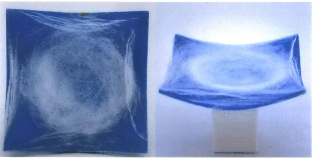
Unlike the two previous series, the Thrust Vault Series is comprised of non-flat 8OX80mm patches varying in topographical features. Sectional height varies across 5mm and 20mm with 5mm increments; each model is repeated twice to validate the consistency of the resulting morphology. Color annotations represent variation in curvature with the color green typically representing anticlastic curvature and blue representing synclastic curvature (Figure 2-11).
Figure 2-11: Series of three-dimensional thrust vault spinning platforms. The assumption was that the variation in fiber density and organization would reflect the morphological constraints given by the environment. Indeed, our results
confirm this correlation below 20mm height (above this height the 3D cocoon ap-peared): a typical model demonstrates increased fiber density along the boundaries. In addition, a circular patch appears at the center of the patch marking the silkworms attempt to form a 3D cocoon between the two planes that make up the section (Figure 2-12).
Figure 2-12: 20mm tall thrust vault spinning platform demonstrating the silkworms spinning behavior.
2.4.6
The Maltese-cross Series
The final series introduces variations in both plan and sectional configurations. The plan configuration in this series is no longer constraint to a completely flat rectangular, polygonal or circular surface patch but rather it is oriented in a Maltese-cross con-figuration. The variation in section height introduces spatial 'gaps' to the silkworm's movement as it spins its silk in circular motion. Sectional height varies between 5mm and 20mm with 5mm increments; each model is repeated twice to validate the consis-tency of the resulting morphology. Color annotations represent variation in curvature with the color green typically representing anticlastic curvature and blue representing synclastic curvature (Figure 2-13).
Figure 2-13: Series of three-dimensional Maltese-cross spinning platforms. As anticipated, the results reflect the correlation between fiber density and surface features, demonstrating a combination between the flat-dice-series and the thrust-vault series.
2.5
Results and Discussion
This work demonstrates that the silkworm Bombyx mori forms fibrous silk networks on flat patches. Fiber density distribution appears to be sufficiently similar to the an-ticipated fiber density variation that was computationally generated for a prescribed membrane structure of the same mass and surface area. In conclusion, the Bombyx
mori silkworm itself may be used as a biological "tool" with which to "compute" fiber
distribution within small-scale 1:1 structures, or as scaled representations of larger architectural structures constructed with fibrous materials.
This work is still in its early stages. The core mechanisms required for fibrous net-work formation can be further captured within a biologically inspired mathematical model that may be useful for anticipating fiber density and organizational variation in fibrous membrane structures exposed to well-defined local loading conditions.
By collecting qualitative and quantitative data from live silkworms spinning on
top of pre-fabricated flat patches a correlation between the nature of material dis-tribution and the geometrical characteristics of the patch was successfully predicted. These results, combined with future research currently under way, have significant implications for structural analysis protocols of fiber-based systems. Additionally this work may also carry implications for biologically-inspired digital design and fab-rication. Here, the relationship between the global, top-down design of a constricting
"environment" designed artificially by the designer informs its local, bottom-up ma-terial manifestation as portrayed by the biological organism (the silkworm). Finally, the Bombyx mori silkworm may be considered as an autonomous agent in processes
of design optimization. As this research has shown, this project opens up new possi-bilities for the use of biological processes as forms of computation.
Chapter 3
Compact & Tunable Material
Deposition in Digital Fabrication
3.1
Introduction
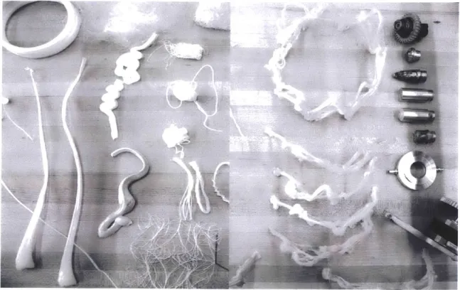
Based on the insight gained in Chapter 2 of this thesis, this chapter presents an array of extrusion heads that aim at increasing material tunability and portability. The figure below illustrates the collections of heads I designed, developed, implemented and tested in the context of specific design projects and their design constraints.
Figure 3-1: Six extrusion heads for tunable material deposition were designed as part of this thesis. Amongst those tools is a freeform extrusion head for tunable geometry without the need for auxiliary support structure; a fast thread deposition head and a fiber winding head for tunable compressive and tensile strength respectively; a portable cable suspended paste droplet extrusion head for tunable drop size of paste material; and a chitosan gel extrusion head for tunable plasticity.
3.2
Compact Freeform Extruder Head for Tunable
Geometry
Figure 3-2: Highlighted: a freeform extrusion head for tunable geometry without the need for auxiliary support structure.
3.2.1
Introduction
Biological Systems
Material systems in Nature are typically composed of graded composites grown and adapted from a single material system rather than an assembly of parts[Oxman, 2011]. More so, growth in the plant and animal kingdoms rarely follows rectilinear paths con-fined to single planes, but instead spreads through space in response to various factors and stimuli[Braam, 2005]. Identical systems and matching fabrication processes can result in substantially different structures, depending on external environmental con-straints. Such is the case with Cecropia silkworms, which can produce silk cylinders and sheets in addition to the canonical silk cocoon[Kloot and Williams, 1953].
In Nature, form typically follows function such that the composition and prop-erties of a material system vary locally as part of the fabrication process. Bombyx
mori silkworms vary the porosity and amount of sericin - a bonding agent between fibers found throughout the layers of their cocoons producing a highly bonded net-work in inner layers compared with outer layers[Chen et al., 2012]. Orb-weaving Ara-neus diadematus spiders spin a wide variety of different silks, ranging from the in-credibly stiff and strong dragline-silk to the glue-coated and highly extensible viscid
In all of Nature's systems, the optimization of material usage and hence metabolic cost plays a necessary role. In tensile systems such as spider webs, there is little mate-rial waste as structural support is an integral part of the web design[Gosline et al., 1986].
3.2.2
Background
Additive manufacturing technologies emerged in the 1980s as a promising method for fabrication and construction automation[Jacobs, 1992]. Today, these additive fabri-cation technologies operate across a wide variety of materials and are used in appli-cations ranging from medical implants to large-scale prototyping. Fused deposition modeling (FDM) systems in particular are found in both hobbyist and professional
3d printing platforms such as the MakerBot Stepstruder, and more professional grade
systems such as the Stratasys Dimension 3D printer. Consistent to all of these systems is the need to use support materials to fabricate certain thin-walled or particularly complex geometries[Levy et al., 2003].
3.2.3
Goals and Objectives
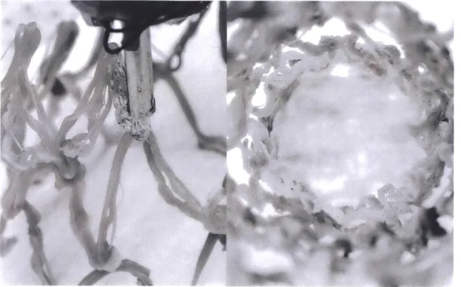
Interest in Freeform Printing was inspired by the concept of self-supporting fiber-based construction in contrast to the scaffold-fiber-based robotic weaving and wrapping explored previously[Tsai et al., 2010]. Here, various natural examples were examined, including silk producing bi-valves, spiders, and silkworms, both wild and domesticated (Fig. 3-3). One of the guiding principles observed among the different natural systems was the concept of producing a continuous fiber-based construction method. (Fig.
Ir
C
I
Figure 3-3: (L.) Bombyx mori silkworm cocoon sequence. (R.) B. mori silkworm spinning in half-sphere.
Initial extrusion of a mono-material was pursued through the employment of a 6-axis KUKA KR5 sixx R850 robotic arm as a means to increase the scale capacity (build volume) of the final result (Fig. 3-4). The ability to create knitted or woven structures requires high levels of robotic dexterity or multiple agents, otherwise re-sulting in the process being rate limited by fiber component length and splicing or tangling of the material.
Dimensions: mm
405 80
A 218
705 24 1.3 613.5
855
Figure 3-4: (L.) Single strand of High-Density Polyethylene (HDPE) freeform print. (R.) KR5 sixx R850 robotic work envelope.
3.2.4
Methedology
Initial Exploration
Preliminary tests explored the use of a Stepstruder tool-head with MakerBot Acry-lonitrile Butadiene Styrene (ABS) filaments to test the concept of drawing a fluid plastic material through space (Fig. 3-5). As a departure from small-scale ABS tests, a custom extrusion tool for attachment to a robotic arm was developed. The design of the tool was based on research into current extrusion devices in industrial appli-cations. The core of the tool is a large 20.6 mm diameter auger-type masonry drill bit cut to a length of 184.5 mm. The goal was to make the housing as compact as possible in order to achieve a high degree of control over the maneuverability of the tool in the robot workspace. (Fig. 3-5).
Figure 3-5: (L.) ABS Filament freeform extrusion. (R.) Custom HDPE extruder mounted on KUKA.
Tool Development
A 3d model of the tool was developed in Rhinoceros 5 for design development,
visualization and fabrication (Fig. 3-6). The housing for the extrusion chamber was constructed out of 50 mm diameter aluminum round stock.
The body and other cylindrical parts of the extruder were turned from round stock on a CNC lathe. The housing was bored to accept the auger bit and then machined from the other end to allow the extruder to accept various interchangeable extrusion tips via three setscrews. The output end of the tool also retained a substantial wall thickness between the bore and the exterior to allow for the placement of up to twelve cartridge-heating elements. Near the top of the tool, the auger bit was machined with an indexed shank to accept a series of water-jet-cut aluminum spur gears. Near the top of the housing at the furthest point from the heater elements an opening was created to feed plastic pellets. Aluminum motor mounts were created using a flexural design to carry the NEMA 23 stepper motor. The motor is controlled by a Gecko G201X Digital step driver to drive the gears turning the auger bit. When the auger bit is turned by the gears, a steady supply of plastic pellets is fed from a hopper through flexible tubing via a venturi for material advancement (Fig. 3-6). As the pellets are transferred down through the housing, the heater cartridges heat the pellets to about
130 degrees C as regulated by an Arduino-controlled thermistor, while the downward
pressure advances the molten material out through the selected tip.
Material Tests
For the proof-of-principle experiments, we chose high-density Polyethylene (HDPE), commonly used today for a variety of applications, ranging from storage contain-ers and furniture products to professional lenses and pipes. In contrast to low-density Polyethylene (LDPE), the HDPE polymer backbone has no branches, yielding stronger intermolecular forces and denser packing. It is therefore more crystalline and
exhibits a higher ratio of tensile strength to density - a property crucial to its ability
to support itself during printing. In addition, its relatively low melting temperature of 130 degrees C allowed us to melt, extrude, and harden it in the air using a compact setup that is easily mountable on the robotic arm.
Figure 3-7: (L.) Tubular and triangular cross-section extrusions. (R.) Custom extru-sion tips & freeform tests.
Tip Development
A variety of tips were explored and developed based on material properties and
deposition processing constraints. The initial tip was developed as a variable diameter and cross section tip (Fig. 3-7.). With an additional stepper motor mounted near the bottom of the extruder, this tip is able to vary between a 10 mm round extrusion to an 8 mm triangulated extrusion profile. Following initial experiments with the variable tip (Fig. 3-7), a series of interchangeable tips were developed, including two tapered single diameter extrusion tips of different length. The diameter of these single extrusion tips consisted of a 3 mm extrusion hole resulting in a 4.5 mm final extrusion.
Additional tips were developed to enable more complex extrusion profiles. For example, one of the tips was designed with a flat 'ribbon-type' extrusion cross-section. The extrusion clearance measurements were 3 mm by 16 mm and resulted in a ribbon extrusion of 4.5 mm by 16.25 mm. Another tip enabled the generation of a hollow
tube-like extrusion with a series of internal fins allowing the molten plastic to flow around and reconnect between the interior walls of the tip and a cylinder shaped interior wall. Advanced versions of this tip incorporated a multi-strand approach inspired by the multi-parts or materials of silkworm's "extrusions". Two multi-strand tips were developed, one with a variety of self-similar holes and another with varying holes. The holes of the second tip contained larger diameter strands on the interior, retaining heat for reconnection; and thinner strands to cool more quickly to support the printing in 3D space (Fig.3-8).
Figure 3-8: (L.) Multi-strand HDPE extrusion close up. (R.) Multi-strand HDPE extrusion in space.
Figure 3-9: (L.) Close-up of HDPE freeform prototype. (R.) Detail of finished HDPE freeform prototype.
3.2.5
Results and Discussion
Testing
The initial variable extrusion was found to be promising in modulating the ex-trusion profile from a complete round strand to a triangulated tapered design. The single strand extrusion profile proved to be the best balance of both heat and rapid cooling for initial print in-space experiments. The first of the multi-strand extrusion experiments proved to be a success and allowed for a quicker vertical extrusion test with the fibers cooling in air. The strands have the potential for multiple-strand bundling as a way of providing additional support (as the structure progresses in vertical space) and self-alignment due to the forces of gravity.
The final multi-strand printing nozzle was modified for the original design to be both longer and thinner for increased agility when printing more complex struc-tures. One of the challenges in many of the freeform printing tests was to provide for
material connectivity to plastic parts previously cooled and hardened. The revised multi-strand tip utilizes five thicker diameter holes at the center and along the outer perimeter, allowing for a balance between quickly cooling strands for structural sup-port as the path is extruded and thicker slower cooling strands, which retain more heat and allow for better reconnection to existing cooled extrusions (Fig.3-9).
It was also found upon attempting more complex path planning and part printing exercises that a longer extrusion tip length allowed for much greater flexibility in the maneuverability of the extruder while attached to the six-axis robotic arm (Fig.3-9).
Future Development
While initial tests were highly dependent on developing custom tooling, future work may explore the further development of active heating and cooling at the tooltip, allowing for greater freedom of possible print geometries. Larger printed systems may be explored through leveraging the strand-like nature of larger printed cells that utilize fibrous interfaces at their edges to assemble a larger fibrous aggregate system.
Future tests could also benefit from substantially expanding the working envelope of the machine. This could, for instance, be a larger scale industrial robotic arm or an autonomous robotic system capable of transporting deposition material to the final desired location(s).
3.2.6
Conclusion
As of yet additive manufacturing methods typically rely on the use of support ma-terials in the fabrication of certain geometries. These mama-terials are used to support overhanging features and undercuts during the construction process, and are typically removed or dissolved upon completion of the print. In powder-based selective laser sintering (SLS) processes the excess material acts as the support of the printed struc-ture, whereas thermoplastic deposition and resin curing processes require additional support structures that are themselves printed.
The research and experiments presented in this section focus on the intersection of biologically inspired design, fibrous construction, mono-material construction and the development of free-form printing. Applications for this novel process are varied
and range from product fabrication to furniture and architectural scale construction. With the elimination of support material in the printing process, printing speeds are increased, and waste is eliminated. The experiments presented in this section provide proof-of-concept for Freeform Printing without support materials. They represent a sustainable approach to additive manufacturing and digital fabrication at large, and point towards new possible directions in sustainable manufacturing.
3.3
Compact Fiber-pulling Head & Fast-thread
Deposition Head for Tunable Fibrous
Compressive Strength
Figure 3-10: Highlighted: a fiber winding head and a fast thread deposition head for tunable compressive and tensile strength respectively.
3.3.1
Introduction
Background
Additive manufacturing and digital fabrication processes such as 3D-Printing typ-ically involve the layered deposition of materials with constant and homogeneous physical properties[Gibson et al., 2010]. Yet all natural materials and biological sys-tems are made of fibrous structures that are locally aligned and spatially organized to optimize structural and environmental performance[Oxman and Mitchell, 2010]. Furthermore, construction processes found in the animal kingdom such as woven
erate, distribute, orient, dandify and assemble fiber-based materials[Benyus, 2009,
Hansell, 2005]. As a result biological structures (including animal architectures)
are considered highly sustainable natural constructions[Benyus, 2009, Robbins, 2002, Hansell, 2005]. Many of these constructions are "designed" by insects well known for their ability to construct highly sustainable structures made of fiber composite materials such as silk[Sutherland et al., 2009].
The section reviews a suit of analytical protocols designed to examine the process of constructing a silk-cocoon by the silkworm. Following, I demonstrate a set of design tools created to reconstruct the cocoon in various length-scales using a 6-axes
KUKA robotic arm. Problem Definition
Fiber-based 3D constructions with spatially varying composition, microstructure and fiber-orientation are omnipresent in Nature[Seidel et al., 2008]. In contrast to natural materials and biological structures, industrially fabricated constructions, such as concrete pillars and fagade panels are typically volumetrically homogenous[Oxman, 2011]. Additive manufacturing platforms such as 3-D printing, provide for the generation of
highly complex geometrical forms. However, despite their formal complexity, these
products and building components are still typically manufactured from materials with homogeneous properties. Compared with biologically constructed fiber-based materials, homogenous constructions fabricated using additive manufacturing
tech-nologies are much less sustainable: from a material perspective - homogeneous
mate-rials offer less potential for structural optimization; and from a fabrication perspective
- additive manufactured components are constructed in layers, relying on the
deposi-tion of significant amounts of wasted support material[Oxman et al., 2012c].
3.3.2
Fiber-Based Construction in Nature
Introducing the Silkworm Bombyx mori
Silk is one of the most ancient, expensive, and highly valued materials in the world[Omenetto and Kaplan, 2010]. It has many applications in textiles, medicine, and industry[Frings, 1987]. This silk is most commonly produced by the
domesti-cated silkworm Bombyx mon. It constructs its cocoon using composite fibrous ma-terial made of fiber (fibroin) and binder (sericin) in order to provide shelter during its transitional stage of pupation[Zhao et al., 2005, Rockwood et al., 2011]. A single fiber is used to construct the cocoon, which is approximately one kilometer in length. The silkworm starts by spinning a scaffolding structure in any three-dimensional space, given it can triangulate and attach its fibers parasitically to its immediate environment. While spinning this scaffolding it will close in onto itself to begin to construct its cocoon within the scaffolding structure. The cocoon itself can be char-acterized by changes in fiber quality transitioning from the inner layers to the outer ones[Zhao et al., 2005].
Silkworm Motion Tracking
Various methods for motion tracking data were considered. Popular methods in-clude visual routines using cameras and/or sensor-based systems[Black and Yacoob, 1995]. The fact that the silkworm cocoons itself within its structure eliminated the use of video-based techniques unable to capture construction processes internal to the co-coon. The challenge was to create a motion-tracking rig on a very small scale that could capture motion data of the silkworm from inside the cocoon as well.
Figure 3-11: Motion tracking of the silkworm Bombyx mori using magnetometer sensors and a 1mm x 2 mm magnet.
An experimental sensor rig 40 mm x 40 mm x 40 mm in dimension was devel-oped using magnetometer sensors placed on 3 planes of the cube. This allowed for data capturing from a 1mm x 2 mm magnet attached to the silkworms' head with cyanoacrylate (Fig. 3-11). After attaching the magnet to the silkworms head, the silkworm was placed within the described space. As expected the silkworm attached its fiber scaffold-ing structure to the walls of the described rig and constructed its cocoon within this defined space.
Figure 3-12: Motion path (top) and point cloud (bottom) in Gener-ative Components
(GC) software.
From the collected data set of Cartesian x, y and z points, a point cloud was visualized (Generative Components Software) as a path, sequenced in time as seen in Figure 3-12.
Motion Tracking Data Evaluation and Speculation for Robotic Emulation on Larger Scale
The captured data demonstrates a clear overall cocoon shape constructed from over 1,000,000 points. The detailed motion path is slightly disrupted by the polar positioning of the magnet as the silkworm spins its cocoon.
This experiment establishes the possibility to convert biological data into robotic motion. The silkworms' actual motion path can be translated into a readable language (Cartesian x,y,z points) and passed on to a robotic arm or any multi-axis material deposition system. This in turn can inform the robotic arm movement in terms of distribution of fiber structures as well as precise fiber placement, as this work-in-progress path simulation demonstrates.
SEM Imaging across Multiple Scales
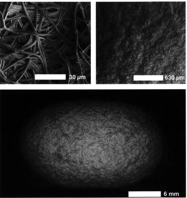
In order to investigate local fiber placement of the cocoon as well as to gain a better understanding of the scaffolding structure, SEM images were taken of the outer layer of the cocoon.
Figure 3-13: SEM images of the silkworm Bombyx mori cocoon across multiple scales (Photo credit: James Weaver, 2013).
Figure 3-13 shows the overall all cocoon form. Its shape and curvature radii largely depend on the silkworms own body structure (i.e. its bending radii) as well as its overall length. This could also inform robotic principles in terms of using the robotic arms reach envelope as a limiting factor or constraint. Furthermore, fiber self-alignment shown in figure 3-14 constitutes a significant aspect of fiber-based con-struction, as the stresses seem to be locally equalized across varying fiber distribution on global scale. This aspect is further discussed in section 3 below.
3.3.3
Fiber-Based Digital Fabrication
Strategies for Robotic Fiber-based Construction on Larger Scales
Based on the analytical protocols developed and reviewed above, a synthetic ap-proach for translating the biological process into a digital fabrication protocol was developed. Several synthesis methods were developed each mimicking a distinct as-pect of the silkworms fiber placement process and its material organization strategies across scales. Three robotic-end-arm-tools were developed to test and analyze novel avenues for fiber-based robotic construction inspired by the silkworms construction methods.
The first approach explores 3D digital construction using a single fiber or a combi-nation of several composite fibers forming a single structural element. A thermoplastic extruder was developed in order to accomplish fiber or multi-strand continuity.
The second approach explores the dual stages in the silkworms cocoon construction process: (a) parasitic construction and (b) cocoon spinning.
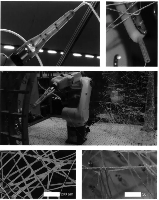
Synthesis 1: Multiple Strand Thermoplastic Extrusion
A Free-Form-Printing tool - inspired by concepts of fiber self-alignment - was
developed and built. A specially designed nozzle for a custom-built high-density-polyethylene (HDPE) thermoplastic extruder was built to allow for local self-alignment of individual strands (Figure 3-14). Self-alignment of fibroin and sericin as observed in the silk fiber inspired the design of an extruder nozzle, which combines fiber and binder as a single material system.
around a single central and larger opening. In this way the HDPE polymer can flow through, before being rapidly solidified by active air-cooling. In this method, the central strand is stabilized by the surrounding thinner strands as well as the outer strands reconnecting to previously extruded strands in close proximity to the overall structure[Rauwendaal, 2001]. Figure 3-14 compares between the biological extrusion process using silk and its digital-fabrication counterpart using composite HDPE. Based on the mono-material synthesis approach using thermoplastic, further experimental synthesis approaches were developed and simulated.
Synthesis 2: Fiber Placement Tools
In this approach, the silkworm cocoon construction is divided into two stages: the first being the parasitic scaffolding and the other being the cocoon construction process itself, as the enclosure within the scaffolding. Fiber-placement in these two phases of the silkworm cocoon construction differs greatly in material quality, orga-nization and function. As the silkworm constructs the scaffolding it "parasites" to its environment, attaching its fibers and pulling it across, connecting to another part of the space repeatedly, building up a three-dimensional web. In the second stage it builds its cocoon in a figure-8 pattern, building up wall thickness for the cocoon over time by constantly reconnecting the fibers locally inside the previously built scaffolding.