HAL Id: hal-00342960
https://hal.archives-ouvertes.fr/hal-00342960
Submitted on 29 Sep 2009
HAL is a multi-disciplinary open access archive for the deposit and dissemination of sci-entific research documents, whether they are pub-lished or not. The documents may come from teaching and research institutions in France or abroad, or from public or private research centers.
L’archive ouverte pluridisciplinaire HAL, est destinée au dépôt et à la diffusion de documents scientifiques de niveau recherche, publiés ou non, émanant des établissements d’enseignement et de recherche français ou étrangers, des laboratoires publics ou privés.
Adel Merabet, Hichem Arioui, Ouhrouche Mohand
To cite this version:
Adel Merabet, Hichem Arioui, Ouhrouche Mohand. Cascaded Predictive Controller design for speed control and Load Torque rejection of Induction Motor. American Control Conference (ACC 2008), Jun 2008, Seattle, WA, United States. pp.1139–1144, �10.1109/ACC.2008.4586646�. �hal-00342960�
Abstract— Cascaded nonlinear predictive controller for
induction motor drive is presented. The load torque, considered as an unknown disturbance, is rejected using a disturbance observer. First, a nonlinear multivariable predictive controller is applied to track electromagnetic torque and rotor flux norm trajectories. Then, a speed predictive control strategy is carried out from the electromechanical equation of the machine. Both controllers are applied in a cascade structure to induction motor. The prediction model is carried out via Taylor series expansion using Lie derivatives for nonlinear model. The derived predictive law minimizes a quadratic performance index of the predicted tracking error for multivariable system and a predicted error for speed control. The implementation of the cascaded control law does not need an on line optimization and the tracking of desired trajectories is achieved successfully. The load torque observer, derived from the speed predictive control, is simplified to a PI structure. This observer structure guarantees the disturbance rejection and the robustness to parameters variations. Simulation results show the high performance of the proposed control scheme.
I. INTRODUCTION
NDUCTION motor (IM) compared to other types of electric machines, exhibits several advantages such as lower cost, reliability, simplicity and less maintenance. However, it is highly nonlinear multivariable and, contrary to DC motor for example, requires more complex methods of control. One of the most significant developments in the control area has been the field oriented control (FOC) proposed by Blaschke [1]. This technique is very useful except that it is very sensitive to parameters variation. To improve FOC, several techniques have been proposed such as full linearizing state feedback control based on differential geometric, direct torque control, sliding mode control, predictive control [2-4]. Even though, these techniques bring improvements to FOC, the research area is open especially for unknown disturbance compensation and robustness to machine parameter.
Model based predictive control (MPC) has received a
Manuscript received Mars 3, 2008. This work was supported in part by the French Research Agency (ANR), in the Framework of VIGISIM Project.
A. Merabet and M. Ouhrouche are with the Applied Sciences Department, University of Quebec at Chicoutimi, Canada (phone: 1 418-545-5011; fax: 1 418-545-5012; e-mails: [email protected], [email protected]).
H. Arioui, is with UFR Sciences et Technologies, Université d’Evry Val d’Essonne, France (phone: 33169477564; fax: 33169477599; e-mail: [email protected]).
great deal of attention and is considered by many to be one of the most promising methods in control engineering [5-7]. It has been extended to nonlinear system [8-10]. The predictive control is applied to induction motor drive with good performance for trajectories tracking [11-14]. However, the performance accuracy is affected by load torque, which is not always known in industrial applications, and the machine parameters uncertainties. To overcome this problem, an estimation of the load torque is done in this paper for compensation of its unknown variations, which constitutes the contribution of this work. The load torque observer can be derived from the predictive control law. The observer has PI structure, where the integral action allows the elimination of the steady state error and enhances the robustness of the control scheme with respect to model uncertainties and disturbances rejection.
II. INDUCTION MOTOR MODEL
The continuous time model of the IM is done in stator reference frame (α-β). Under the assumption of linearity of the magnetic circuit, the nonlinear affine form can be expressed as
)
(
)
(
)
(
)
(
t
f
x
g
x
u
t
x
&
=
+
(1) where T r r s si
i
]
[
α βφ
αφ
βω
=
x
T s s u u ] [ α β = uThe state x belongs to the set =
{
∈ℜ : 2 + 2 ≠0}
β αφ
φ
r r 5 x ΩVector function f(x) is defined as follows
(
)
⎥ ⎥ ⎥ ⎥ ⎥ ⎥ ⎥ ⎥ ⎥ ⎥ ⎥ ⎥ ⎦ ⎤ ⎢ ⎢ ⎢ ⎢ ⎢ ⎢ ⎢ ⎢ ⎢ ⎢ ⎢ ⎢ ⎣ ⎡ − − + − − − − + − + + − = ω φ φ ωφ φ ωφ φ ωφ φ γ ωφ φ γ α β β α α β β β α α α β β β α α J f i i JL pL p T i T L p T i T L pK T K i pK T K i r s r s r r m r r r s r m r r r s r m r r r s r r r s 1 1 ) ( x f g is a constant matrixCascaded Predictive Controller Design for Speed Control and Load
Torque Rejection of Induction Motor
Adel Merabet, Hichem Arioui and Mohand Ouhrouche
[
]
T s s L L g g ⎥ ⎥ ⎥ ⎥ ⎦ ⎤ ⎢ ⎢ ⎢ ⎢ ⎣ ⎡ = = 0 0 0 1 0 0 0 0 0 1 2 1 σ σ gThe outputs to be controlled are the electromagnetic torque and the squared rotor flux norm
⎥ ⎥ ⎥ ⎦ ⎤ ⎢ ⎢ ⎢ ⎣ ⎡ + = = = − = = = = 2 2 2 2 2 1 1 ( ) ) ( β α α β β α φ φ φ φ φ r r r s r s r r m h y i i L L p h y x h y (2)
III. NONLINEAR PREDICTIVE CONTROL
The optimal control is carried out through the minimization of the receding performance index defined as
( τ τ ) ( τ τ )τ τ τ d t t t t T
∫
+ − + + − + = ℑ 2 1 ) ( ) ( ) ( ) ( 2 1 ) , (xu y yr y yr (3)The control weighting term is not included in the performance index (3). However, the control effort can be achieved by adjusting the minimum and maximum prediction times τ1 and τ2 respectively [9].
The τ-step ahead prediction of the system outputs is obtained via Taylor series expansion.
) ( ) ( ! ) ( ! ... ) ( ! 2 ) ( ) ( ) ( ) 1 ( 2 2 t h L L r h L r h L h L h t y i r i r i r i r i i i i i i i i u x x x x x f g f f f − + + + + + = + τ τ τ τ τ (4)
The following notation is used for the Lie derivative of the function hj(x) along a vector field f(x) = [f1(x) ... fn(x)]T
) ( ) ( 1 x f x x f ∂ ∂ = ∂ ∂ =
∑
= j n i i i j j h f x h h L (5) Iteratively, we have ) ( ( 1) j k j kh L L h L = − f f f ) ( x x f f g h L h L L j j g ∂ ∂ = (6)For torque output, the relative degree is r1=1
⎩ ⎨ ⎧ + + = = ) ( ) ( ) ( ) ( ) ( ) ( ) ( ) ( 1 1 1 1 1 1 2 1h u t L h u t L h L t y h t y s g s g x α x β x x f & (7)
For rotor flux norm output, the relative degree is r2=2
⎪ ⎩ ⎪ ⎨ ⎧ + + = = = ) ( ) ( ) ( ) ( ) ( ) ( ) ( ) ( ) ( ) ( 2 2 2 2 2 2 2 2 2 2 1Lh u t L L h u t L h L t y h L t y h t y s g s g x α x β x x x f f f f & & & (8)
The expansion of the induction motor outputs y(t+τ) in rith (with r1=1 and r2=2) order Taylor series under matrix
form is
(
(
)
(
)
(
)
)
)
(
t
T
Y
x
H
x
u
t
y
+
=
∏
+
(9) where ] * ) 2 / ( * [ 22 2 2 2 2 2× × × = ∏ I T I T I T h L h L h L h h ( ) ( ) ( ) ( ) 0 ( )] [ ) ( 2 2 2 1 2 1 x x x x x x Y = f f f T g g g g h L L h L h L L h L ⎥ ⎦ ⎤ ⎢ ⎣ ⎡ = ) ( 0 0 ) ( 0 0 ) ( 0 0 ) ( 0 0 ) ( 2 1 2 1 2 2 1 1 x x x x x H f f I.×. : identity matrix.The predicted reference yr(t+τ) can be approximated by
Taylor series expansion, and given by
) ( ) (t r t r Y y +
τ
=∏ (10) where T r r r r r t y t y t y t y t y t) [ ( ) ( ) ( ) ( ) 0 ( )]( = 1 2 &1 &2 &&2
r
Y
The performance index (3) can be simplified as
)] ( ) ( ) ( ) ( [ )] ( ) ( ) ( ) ( [ 2 1 t t t t T r r Yx Hxu Y Y u x H x Y + − ∏ + − = ℑ (11) where
∏
=
∫
∏
∏
2 1 τ ττ
d
TThe necessary condition of optimal control is given by
0 = ∂ ∂ℑ
u (12) Then, the optimal nonlinear control law, which minimizes the receding horizon performance index (3), is given by
(
( ) ( ))
( )(
() ( ))
)
( H x Hx 1H x Y Yx
ut = T ∏ − T ∏ r t − (13) IV. SPEED PREDICTIVE CONTROL
The mechanical dynamic of IM is described by
) ( 1 ) ( 1 ) ( ) ( T t J t T J t J f t = − r ω + e − L ω& (14) where,
) (φrαsβ φrβsα r m e i i L L p
T = − and considered as control input. TL is the load torque, which is considered as an unknown
disturbance in the system dynamics.
A simple predictive control algorithm is carried out for this system, which consists of applying a control that allows the tracking error of speed to reach zero.
0 ) ( ) ( +τ −ω +τ = ω t r t (15)
The predicted speed ω(t+τ) is carried out by Taylor series expansion ⎟ ⎠ ⎞ ⎜ ⎝ ⎛− + − + = + = + ) ( 1 ) ( 1 ) ( ) ( ) ( ) ( ) ( t T J t T J t J f t t t t L e r r ω τ ω ω τ ω τ ω & (16)
Similarly, The predicted reference speed ωr(t+τ) is
approximated as ) ( ) ( ) (t r t r t r τ ω τω ω + = + & (17)
The optimal control is carried out from (15), (16) and (17). It is given by
(
() ())
() () () ) (t J t t f t J t T t Te =− ω −ωr + rω + ωr + L τ & (18)The cascaded control structure of IM system is obtained by using the torque, calculated from the speed control law, as reference torque for the nonlinear predictive controller developed above. Thus, the initial system can be decomposed into two subsystems in cascaded form. The inner loop incorporates torque-flux model and the external loop is the equation of the mechanical dynamics of motor.
V. LOAD TORQUE COMPENSATION
The accuracy of the speed control law for trajectory tracking needs the knowledge about the load torque. Since TL is an unknown variable, it should be estimated in the
controller as TˆL in order to eliminate the effects of disturbance.
In this paper, a load torque observer is introduced for estimating TL. In order to simplify the design of the
observer, since there is no information about the load torque and the observer period in the actual system is short enough compared with the variation of TL, it is possible to
make the following assumption:
0 =
dt
dTL (19)
It follows from (14) that
) ( 1 ) ( ) ( ) ( 1 t T J t J f t t T J e r L = + − − ω& ω (20)
An initial disturbance observer is given by
⎟ ⎠ ⎞ ⎜ ⎝ ⎛ + − + = 1 ˆ () () 1 () ) ( ˆ 0 0 T t J t J f t p T J p t TL L ω& rω e & (21)
where p0 is a parameter to be chosen.
The observation error is given by
) ( ˆ ) ( ) (t T t T t e = L − L (22)
Then, the error dynamics is given by
(
( ) ˆ ( ))
1 ( ) 1 ) ( ˆ ) ( ) ( 0 0 J T t T t p J e t p t T t T t e L L L L = − = − = & & & (23)p0 must be chosen negative such that the system
0 ) ( 1 ) ( − 0 e t = J p t e& (24) is exponentially stable.
The load torque TL is replaced by its estimation TˆLin the
control law (18)
(
( ) ( ))
( ) ( ) ˆ ( ) ) (t J t t f t J t T t Te =− ω −ωr + rω + ωr + L τ & (25)Then, the control law (25) is embedded into the disturbance observer (21)
(
() ())
(
() ())
) ( ˆ 0 0 t t p t t p tT&L = ω& −ω&r + τ ω −ωr
(26) Integrating (26), we get
(
−)
+∫
(
−)
= r t r L d p t t p t T 0 0 0 () () ( ) ( ) ) ( ˆ ωτ ω τ τ τ ω ω (27)The load torque disturbance observer has a PI structure, which compensates the unknown load torque and enhances the robustness for the speed tracking.
VI. ROTOR FLUX ESTIMATOR
The rotor flux estimator, used in this work, is carried out from the Kalman filter (KF) applied to the 4th order discrete
linear time varying model depending on the measured speed ⎩ ⎨ ⎧ + = + + = + ) ( ) ( ) ( ) ( ) ( ) ( ) ( ) ( ) 1 ( k k C k k k k B k k A k v x y w u x x (28) where T s s T s s T r rα s s k i k i k k u k u k k k k i k i k ] ) ( ) ( [ ) ( ] ) ( ) ( [ ) ( ] ) ( ) ( ) ( ) ( [ ) ( β α β α β β α φ φ = = = y u x
w(k) and v(k) are independent noises with covariance
E{w(k)w(k)T }=Q , E{v(k)v(k)T }=R (29)
Discrete time Kalman filter equations
(
( 1))
( 1/ ) ) 1 / 1 ( )) / 1 ( ˆ ) 1 ( )( 1 ( ) / 1 ( ˆ ) 1 / 1 ( ˆ ) ) / 1 ( ( ) / 1 ( ) 1 ( ) ( ) / ( ) ( ) / 1 ( ) ( ) ( ) / ( ˆ ) ( ) / 1 ( ˆ 1 k k P C k K I k k P k k C k k K k k k k R C k k CP C k k P k K Q k A k k P k A k k P k k B k k k A k k T T T + + − = + + + − + + + + = + + + + + = + + = + + = + − x y x x u x x Initial conditions{ }
P E{
T}
E ; ( ˆ )( ˆ ) ˆ0 x0 0 x0 x0 x0 x0 x = = − − (31) The matrices A, B and C are carried out from the discretization of the continuous model of induction motor. ⎥ ⎥ ⎥ ⎥ ⎥ ⎥ ⎥ ⎥ ⎥ ⎦ ⎤ ⎢ ⎢ ⎢ ⎢ ⎢ ⎢ ⎢ ⎢ ⎢ ⎣ ⎡ − − − − − − = r s s r m s s r s r m s r s s s s r s s T T k p T T L T k p T T T T L T T K T k pK T T k pK T T K T T k A 1 ) ( 0 ) ( 1 0 ) ( 1 0 ) ( 0 1 ) ( ω ω ω γ ω γ T s s s s L T L T B ⎥ ⎥ ⎥ ⎥ ⎦ ⎤ ⎢ ⎢ ⎢ ⎢ ⎣ ⎡ = 0 0 0 0 0 0 σ σ ⎥ ⎦ ⎤ ⎢ ⎣ ⎡ = 0 0 1 0 0 0 0 1 C whereTs is the sampling time.
Fig. 1 shows the proposed control scheme for the induction motor drive.
VII. SIMULATION RESULTS
The simulations have been carried out to verify the performance of the proposed cascaded controller. The details about the motor are given in appendix.
The digital model of the motor is run with sample time Ts = 1 μs. The modulation time of the SV PWM is Tm = 100
μs. The information about the rotor speed is assumed to be known by measurement, the rotor flux is estimated by Kalman filter with sample time Ts = 5 μs. The sample time
of the controller is Ts = 100 μs, the prediction times for
inner controller are chosen as τ1 = 0, τ2 =10*Ts= 1 ms and
for external controller τ=50* Ts= 5 ms and p0= -5.
First, the machine controlled by the cascaded control law is run with the nominal values of the machine parameters. The tracking performances for rotor speed and rotor flux norm are shown in Fig. 2 and 3 respectively. The noise, shown in flux estimation, occurs from the different sample times used in simulation. Fig. 4 gives the estimation of the load torque. As shown in results, the tracking performance is achieved successfully. (30) IMIM DC V + IM NPC usa* usb* usc* αβ is, abc us, abc αβ r ω usβ* PC usα* L Tˆ PI Rotor Flux Estimator (KF) is, αβ us, αβ ω Load torque observer
− αβ φr r e T 2 r φ ω Predictive + PI control abc abc
Fig. 1. Block diagram of cascaded nonlinear predictive control for induction motor drive
Fig. 2. Rotor speed and speed error responses of induction motor drive
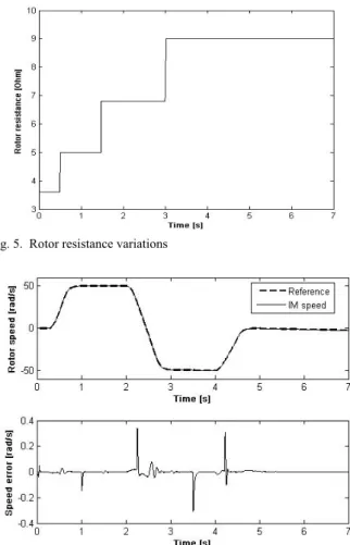
Then, in case of mismatched model, the rotor resistance (Rr) is varied as shown in Fig. 5. This variation is not taken
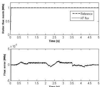
into account when the control law is carried out. The nominal value of the rotor resistance is used in the control law computation. The same prediction times as above are used in this simulation. The tracking performances for speed and flux norm with smooth speed reference are shown in Fig. 6 and 7 respectively, and Fig. 8 gives the estimated load torque. These results show that the robustness to Rr variation is achieved by this controller.
However, the accuracy of the load torque estimator is decreased in this case. It can be seen that the response performance of the system is good even though the parameter variation is not adapted on line.
VIII. CONCLUSION
A cascaded nonlinear predictive control algorithm with a load torque disturbance observer of an induction motor drive has been proposed. The nonlinear predictive controller is developed for multivariable system of the induction motor in order to track electromagnetic torque and rotor flux norm. It constitutes the inner loop of the system. The external loop is dedicated to speed tracking with a simple predictive controller. It has been shown that this kind of control is effective for solving the control problem of induction machines. Although the predictive control belongs to optimal control, it does not need an on-line optimization and trajectories tracking is successfully achieved. The load torque disturbance, considered as unknown, is estimated by a simple observer and has a PI structure. Faster load torque disturbance compensation is guaranteed, and robustness with respect to machine parameter is enhanced with this cascade structure control design. An appropriate and simple choice of the tuning parameters provides a robust controller, very well adapted for trajectories tracking problem.
Fig. 4. Load torque estimation
Fig. 5. Rotor resistance variations
Fig. 6. Rotor speed and speed error responses of induction motor drive of mismatched model
Fig. 7. Rotor flux norm and flux error responses of induction motor drive of mismatched model
APPENDIX
REFERENCES
[1] F. Blaschke, “The principle of field orientation applied to the new transvector closed loop system for rotating field machines,” Siemens
Rev., 34, pp. 217-220, 1972.
[2] M. Barut, S. Bogosyan and M. Gokasan, “Speed sensorless direct torque control of IM’s with rotor resistance estimation,” Energy
Conversion and Management, 46, pp. 335-349, 2005.
[3] F. Chen, and M.W. Dunnigan, “A new non-linear sliding-mode for an induction motor machine incorporating a sliding-mode flux observer,” International Journal of Robust and Nonlinear Control, 14, pp. 463-486, 2003.
[4] J. Chiasson, “Nonlinear controllers for an induction motor,” Control
Engeineering Practice, vol.4, no.7, pp. 977-990, 1996.
[5] C.E. Garcia, D.M. Prett and M. Morari, “Model predictive control: theory and practice- a survey,” Automatica, 3, pp. 335-348, 1989. [6] J. Richalet, “Industrial Applications of Model Based Predictive
Control,” Automatica, vol. 29, no. 5, pp. 1251-1274, 1993.
[7] C. Bordons, and E.F Camacho, “A generalized predictive controller for a wide class of industrial processes,” IEEE Transactions on
Control Systems Technology, 6, no. 3, pp. 372-387, 1998.
[8] L. Ping, “Optimal Predictive Control of Continuous Nonlinear Systems,” International Journal of Control, vol. 63, no. 1, pp. 633-649, 1996
[9] W.-H. Chen, D.J. Balance and P.J. Gawthrop, “Optimal Control of Nonlinear Systems: A Predictive Control Approach,” Automatica, vol. 39, no. 4, pp. 633-641, 2003.
[10] W.-H. Chen, D.J. Balance, P.J. Gawthrop, J.J. Gribble and J. O’Reilly, “Nonlinear PID predictive controller,” IEE Proceedings
Control Theory application, vol. 146, no. 6, pp. 603-611, 1999.
[11] W. Feng, J. O’Reilly and D.J. Balance, “MIMO Nonlinear PID Predictive Controller,” IEE Proceedings Control Theory application, vol. 149, no. 3, pp. 203-208, 2002.
[12] D. Dumur, P. Boucher and J. Röder, “Design of an open architecture structure for implementation of predictive controllers for motors,” IEEE Conference on Control Applications, Trieste, Italy, pp. 1307-1311, 1998.
[13] M.K. Maaziz, P. Boucher and D. Dumur, “A New Control Strategy for Induction Motor Based on Non-linear Predictive Control and Feedback Linearization,” International Journal of adaptive Control
and Signal Processing, 14, pp. 313-329, 2000.
[14] R. Hedjar , R. Toumi , P. Boucher and D. Dumur, “Two Cascaded Nonlinear Predictive Controls of Induction Motor,” IEEE
Conference on Control Applications, vol. 1, Istanbul, Turkey, pp.
458-463, 2003.
[15] A. Merabet, M. Ouhrouche, R-T. Bui and J. Thongam, “Nonlinear multivariable control of induction motor based on generalized predictive control,” 8th IASTED International Conference Control
and Applications, Montreal, Canada, pp. 07-12, 2006.
TABLEI
MACHINE AND CONTROLLER PARAMETERS
Symbol Quantity isα , isβ stator currents β α φ φr , r rotor fluxes ω rotor speed usα , usβ stator voltages
Rs , Rr stator and rotor resistances
Ls , Lr , Lm stator, rotor and mutual inductances
Tr = Lr / Rr rotor time constant
p poles pair number
J inertia
fr, friction coefficient
TL load torque
σ leakage coefficient
τ1 , τ2 minimum and maximum prediction times
p0 disturbance observer gain
Ts sampling time. ⎟⎟ ⎠ ⎞ ⎜⎜ ⎝ ⎛ + = = − =1 2 ; ; 1 22 r m r s s r s m r s m L L R R σL L L L K L L L γ σ σ Rs = 8 Ω, Rr = 3.6 Ω, Ls = 0.47 H, Lr = 0.47 H, Lm = 0.44 H, p = 2, J = 0.06 kgm2, f r = 0.04 Nms