HAL Id: hal-01339360
https://hal.archives-ouvertes.fr/hal-01339360
Preprint submitted on 29 Jun 2016
HAL is a multi-disciplinary open access
archive for the deposit and dissemination of
sci-entific research documents, whether they are
pub-lished or not. The documents may come from
teaching and research institutions in France or
abroad, or from public or private research centers.
L’archive ouverte pluridisciplinaire HAL, est
destinée au dépôt et à la diffusion de documents
scientifiques de niveau recherche, publiés ou non,
émanant des établissements d’enseignement et de
recherche français ou étrangers, des laboratoires
publics ou privés.
Selective manipulation of microscopic particles with
swirling Rayleigh waves
Antoine Riaud, Michael Baudoin, Olivier Bou Matar, Loic Becerra,
Jean-Louis Thomas
To cite this version:
Antoine Riaud, Michael Baudoin, Olivier Bou Matar, Loic Becerra, Jean-Louis Thomas. Selective
manipulation of microscopic particles with swirling Rayleigh waves. 2016. �hal-01339360�
Antoine Riaud
Institut d’Electronique, de Micro´electronique et Nanotechnologie (IEMN), LIA LICS, Universit´e Lille 1 and EC Lille, UMR CNRS 8520, 59652 Villeneuve d’Ascq, France and
CNRS UMR 7588, UPMC Universit´e Paris 06, Institut des NanoSciences de Paris (INSP), F-75005, Paris, France
Michael Baudoin and Olivier Bou Matar
Institut d’Electronique, de Micro´electronique et Nanotechnologie (IEMN), LIA LICS, Universit´e Lille 1 and EC Lille, UMR CNRS 8520, 59652 Villeneuve d’Ascq, France
Loic Becerra and Jean-Louis Thomas
CNRS UMR 7588, UPMC Universit´e Paris 06, Institut des NanoSciences de Paris (INSP), F-75005, Paris, France (Dated: June 29, 2016)
Acoustical vortices offer tremendous perspective for dexterous contactless manipulation. In order to fulfill their potential of selective though label-free biocompatible tweezers, they must nonetheless become flat, smaller and easily integrable with disposable substrates. In this letter, we synthesize acoustic vortices using an integrated transducer by solving an inverse problem. We then capture and pattern tens of 30 µm particles on disposable substrates. Finally, we compare the forces applied by our vortices to theoretical calculations. This technology offers numerous prospects for micro-fabrication and cell-printing.
High precision contactless manipulation offers tremen-dous perspectives for biophysical investigations and breakthroughs such as biological cell printing. A large span of methods using magnetic [1, 2], optical [3, 4], elec-trical [5] and acoustical forces [6, 7], and their combina-tion [8] have been proposed. Among these techniques, acoustic tweezers stand out for cell manipulation appli-cations as they combine high bio-compatibility [9], label-free manipulation [10], relatively low cost and disposable parts for minimized sample contamination [11]. One ap-proach to capture individual particles relies on an ultra-sonic beam in the Mie scattering regime (particle size >> wavelength) [12]. Herein, very high frequencies (between 100 MHz and 1 GHz) are required to achieve selective manipulation, resulting in a deleterious heating of the manipulated sample [13] and the need of high-end elec-tronics.
Alternative technologies based on Rayleigh scattering (particle size << wavelength) allow contactless manip-ulation of micro-objects at much lower frequency (30 MHz). In the first one [14, 15], two orthogonal standing surface acoustic waves (SAWs) create an egg-box poten-tial well network where numerous particles can be cap-tured and translated at once. Standing SAWs traps are flat devices easily miniaturized [16], and benefit from an expeditive fabrication by photolithography. Nonetheless, the simple nature of the acoustic field generated by this kind of device are unsuitable to manipulate selectively one particle within a cluster.
Dexterous and selective contactless manipulation was recently achieved [17–19] using acoustical vortices. These helical waves spin around a phase singularity where wave-front dislocation yields a total cancellation of the beam amplitude. This dark spot is wrapped by a bright ring
of maximum sound intensity which in turn enables a se-lective trapping at this dark focus [20]. Nevertheless, the synthesis of acoustical vortices is challenging: it requires most often a network of numerous transducers controlled by a high-end programmable electronics. In such configu-ration, the large number of individual transducers makes the miniaturization challenging and the electronic hard-ware skyrockets the device cost. Finally, these devices and their successive improvements [21, 22] are not flat which complicates integration with other microfluidic el-ements.
We recently expanded the surface acoustic wave tool-box with the 2D anisotropic analog of acoustical vortices called swirling SAWs [23]; these waves in turn generate acoustical vortices when immersed in a liquid [24]. Sim-ilarly to their 3D analog, the experimental synthesis of swirling SAWs is challenging and so far involves 32 in-terdigitated transducers (IDT) controlled independently by a high end programmable electronics. In this letter, we synthesize swirling SAWs and acoustical vortices with a single spiraling IDT and a single oscillating voltage source. These spiraling IDTs constitute the core of a new class of swirling SAW acoustic tweezers able to gen-erate acoustical vortices at remote locations trough sev-eral layers of materials. We quantify the forces applied by the acoustic radiation pressure of these vortices on 30 µm polystyrene (PS) particles. We then use this tweez-ers to pattern individually several dozens of particles. This technology is selective, label-free, cheap, flat, easy to miniaturize, biocompatible and involves disposable chips. It could finally allow acoustic tweezers to reach standard laboratory workbench and enable a whole range of new biophysical assays and micro-fabrication processes.
2
FIG. 1. The transducer is a pair of spiraling interdigitated gold electrodes deposited on a piezoelectric substrate. A mi-croscope slide is placed on the transducer, and acoustic con-tact is ensured by the mean of a thin layer of silicon oil. An aqueous suspension of micrometric polystyrene beads is dis-persed between the microscope slide and an upper layer of PDMS that plays the role of acoustic absorber. The center of the vortex is visualized by a reticule.
static part (the transducer) and a mobile part (the sub-strate) placed atop of it, sandwiching a very thin match-ing layer of silicon oil. We displace individual particles by placing the transducer below one of them, turning the power on, moving the transducer and the captured ob-ject to the desired place and then turning the power off again. For practical reasons (simpler electrical connec-tions and visualization), the transducer is fixed in the laboratory frame and the sample is mobile by the mean of a micromanipulator.
Surface acoustic waves are nanometric mechanical vi-brations of pulsation ω propagating at the surface of a generally anisotropic substrate with a slowness sSAW(ψ) that depends on the direction of propagation ψ. This dispersion relation restricts the variety of fields that can be synthesized. Any surface acoustic wave can therefore be written as follows [23]:
Ξ(0) = eiω(t−τ ) Z π
−π
H(0)(ψ)e−iωh(ψ,θ)rdψ, (1)
where Ξ(0)is the normal vibration amplitude of the
sub-strate at the point (r, θ) in polar coordinates and at time t. We introduce the convenient notation h(ψ, θ) = sSAW(ψ) cos(ψ − θ). In equation (1), H(0) is the angular spectrum of the wave, that is the relative weight of the plane waves for each direction ψ. The angular spectrum is the sole degree of freedom in equation (1). For subse-quent discussion, we introduce the complex phase µ and amplitude ξ of H(0)(ψ) = ξ(ψ)eiµ(ψ)and a delay τ .
At the surface of piezoelectric materials, surface acous-tic waves combine periodical displacements in the three
directions of space and electrical oscillations, the propor-tion of each of them being ψ-dependent. In the following, we will refer to a(ψ) as the normal substrate vibration amplitude per unit voltage. (a and sSAW are provided in the supplemental material). Reversely, this fundamental electromechanical coupling ensures that forcing an alter-native current through a piezoelectric substrate provokes periodical deformations of the solid. IDTs are a special pattern of electrodes that reinforce these vibrations by constructive interferences. Here, an alternate grating of hot and ground electrodes with the same spatial period as the wave generates a surface wave when it vibrates in phase with the SAW. It is nonetheless challenging to fulfill these resonance conditions due to the substrate anisotropy, which restricts interdigitated transducers to plane waves and in very few cases to focused waves. Con-sequently, although swirling SAWs have been experimen-tally synthesized, no mathematical background is cur-rently available to design a suitable integrated transducer for these waves.
In the supplemental material, we conceive an inte-grated transducer suitable to generate an arbitrary SAW field Ξ(0). In our calculations, the hot and ground
elec-trodes run along a polar curve R(Ω) and are exposed to an alternative tension V (Ω): V (Ω) = eiωt ξ( ¯ψ + π) √ 2π |a( ¯ψ)|pR(Ω)ω|h00( ¯ψ, Ω)|, (2) R(Ω) =ψ0+ α( ¯ψ) − π 4sgn(h 00( ¯ψ, Ω)) − µ( ¯ψ + π) ωh( ¯ψ, Ω) , (3) where ψ0is a free parameter: ψ0= ωτ + bπ for the hot
electrode and ψ0 = ωτ + (b + 1)π for the ground, with
b ∈ Z a dummy parameter introduced for symmetry rea-sons (see the derivation of equations (2) and (3) in the supplemental material). α( ¯ψ) is the complex argument of a( ¯ψ). In this equation, the beam stirring angle Ω − ¯ψ(Ω) is defined by h0( ¯ψ) = 0 with h0=∂ψ∂h. As pointed out by Laude et al [25], h( ¯ψ, Ω) is related to the group velocity vg(Ω) = 1/h( ¯ψ, Ω). The termp|h00( ¯ψ, Ω)|, proportional
to the phonon focusing factor, may vanish for some ma-terial cuts in some directions, in which case it yields cus-pidal points and caustics. In equations (2) and (3) the offset of π of µ and ξ arguments represents the fact that the electrode located at Ω generates a plane wave propa-gating with a direction ¯ψ(Ω) + π. The term√R accounts for the antenna gain of the transducer.
Although R is fairly easy to calculate and tune, V —the excitation magnitude of a specific IDT portion —mostly depends on a(ψ) which is specific to the ma-terial and its cut (see also [26]). Setting V may involve the ability to apply different voltage magnitudes on dif-ferent finger pairs or increasing the number of finger pairs in the directions of weaker coupling a( ¯ψ).
An exciting application of this inverse problem is the synthesis of acoustic vortices, which may in turn achieve selective contactless manipulation of microparticles and biological cells. According to earlier studies [23], the acoustic field radiated by anisotropic substrates can only generate anisotropic swirling SAWs (as opposed to usual Bessel beams): Wl= eiωt 2πil Z π −π ρ(ψ)eilψ−ih(ψ,θ)rdψ, (4) where l is the topological charge of the vortex, and ρ(ψ) is a free parameter to give some flexibility for later dis-cussion.
It was also shown that anisotropic waves are prone to degeneration when traveling through isotropic media [24]. This degeneration can be controlled by synthesiz-ing adequate precursor waves of angular spectrum H(0)
on the substrate that degenerate into the desired field of angular spectrum H(n)after crossing n superstrates. Ac-cording to the angular spectrum propagation calculations in supplemental material, we get:
H(0)= H(n)eiωT, (5) T = n X i=1 s(i)z (zi− zi−1), (6) s(i)z = q s(i)2− s SAW 2, (7)
with, in the case of acoustical vortices, H(n)= ρ(ψ)eilψ
2πil . (8)
eiωT is the propagator, where T represents the direction-dependent delay due to the propagation across n super-strates of slowness s(i), i ∈ {1..n} with their interface
lo-cated at zi. In order to create the acoustic vortex given
by equation (4), we generate the precursor wave which angular spectrum is given by equation (5) and (8). This wave is in turn synthesized by the transducer described by equation (3). Those calculations are implemented in the Python code in supplemental material.
Importantly, equations (3) and (5) show that R de-pends on the frequency of actuation, the slowness of the piezoelectric substrate and the superstrates, and on the thickness of each superstrate layer. Accordingly, each transducer has to be designed specifically for this set of parameters. This is not very restrictive since standard-ized microscope slides and coverslips made of glass and other materials are readily available.
Remarkably, the final geometry of the transducer seems suitable for super-harmonic generation. Accord-ingly, harmonic m is expected to generate an acoustic vortex of charge lm when excited at a pulsation ωm= mω
(proof in the supplemental material).
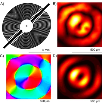
In a first set of experiments, we fabricated the trans-ducer shown in figure 2.A to form acoustical vortices W1
A) 5 mm B) 5 mm 500 µm 500 µm 500 µm D) C)
FIG. 2. A) Spiraling swirling SAW transducer (W1 at 10
MHz across #1 glass coverslip), B) Experimental substrate vertical vibrations amplitude (max amplitude 1.4 nmppat 7
Vrms), C) Experimental substrate vertical vibrations phase,
D) Calculated potential well from experimental data (max height 6.3 fJ)
across a typical glass coverslip (#1 borosilicate, thick-ness 200 µm). The lithography process and the masks are available in supplemental material. The transducer twists hot and ground electrode in a double Archimedes spiral. The diameter of the device is constrained by the attenuation of the leaky surface wave, approximately 2 dB/MHz/cm. The hot and ground electrodes are con-nected on opposite supply branches, the branches them-selves being located in the minimal piezoelectric coupling directions. The working frequency of this specific de-vice is 10 MHz, which corresponds to wavelengths near 400 µm and optimal object size close to 70 µm [16, 17]. Standard lithography workbench allows resolutions up to 1 µm, which lets envision the manipulation of sub-micrometric object with a similar setup.
In order to measure the vertical vibrations created by this transducer, we coated a glass coverslip with a thin layer of gold. We then measured the vertical vibration amplitude of the susbtrate (see figure 2.B and C) using a home-made vibrometer described previously [23]. The experiment is as follows: we drop a small volume of sili-con oil (1.0 Pa.s) directly on the transducer surface and then squeeze the liquid with a gold-coated coverslip. Fi-nally, we add a small droplet of water and cap it with a millimeter thick block of cross-linked polydimethyl-siloxane (PDMS) to minimize acoustic reflections. The Michelson vibrometer then measures the vibrations of the top surface of the coverslip. Accordingly, the vortex di-ameter sizes roughly λ/2 = 175 µm. The phase
singu-4
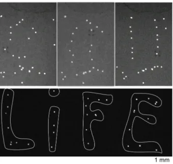
FIG. 3. Manipulation of 30 µm PS beads. Top: rearrange-ment of a random distribution of beads into of two vertical lines. Bottom: writing of the word LIFE with 33 particles.
larity shown in figure 2.C is clearly visible and validates the calculation of R. It results directly in the dark core in the center of figure 2.B. Knowing the vertical vibra-tion amplitude (about 1.4 nmpp at 7 Vrms), it is possible
to compute the force applied by this vortex on spheres. In the case of small particles, this force is the gradient of the potential [27] shown in figure 2.D. The theoretical cal-culation and maximum displacement speed experiments (details in supplemental material) agree quantitatively well on a maximum force of 200 pN on 30 µm PS spheres at 7 Vrms, which is also the upper bound of optical
tweez-ers [4].
We then used a similar transducer to arrange sets of dozens of 30 µm PS spheres. The rearrangements took a few minutes and is shown in figure 3. It happens by iter-atively grabbing, moving and dropping individual beads as mentioned earlier (see video in supplemental material). These rearrangement experiments may be perturbed by the secondary basin of attraction on the edge of the vortex which can also capture individual beads. Thus, a competition between the acoustic radiation pressure of the vortex at the core and the secondary rings, and the friction due to the fluid and the solid will decide which beads stay in place and which ones move with the vortex. Therefore, the selectivity of the device comes from the larger force at the center of the vortex than on the sec-ondary rings which allows choosing a friction threshold in between. Since PS beads showed little friction with glass, we switched to poly(methyl methacrylate) (PMMA) cov-erslips with a thickness of 2.0 mm and modified the trans-ducer accordingly (mask in supplemental material).
The iterative process to form two lines of particles on this PMMA superstrate is shown at the top of figure 3, and the final arrangement of 33 beads to form the word LIFE is shown at the bottom of figure 3. We believe such rearrangement is figurative of future biological and other microstructures sequential assembly where numerous dif-ferent cells or particles could be arranged in space.
In this paper, we solved an inverse problem to design integrated transducers for arbitrary acoustic fields. We then applied this solution to design an integrated spi-raling transducer for acoustic vortices. The resulting acoustic field efficiently captures individual micrometric particles with forces up to 200 pN. The insertion of a micromanipulator to force a relative motion between the transducer and the container of the beads allows selective rearrangements of dozens of microspheres. This research opens exciting prospects for cell printing and tissue en-gineering where dozens of different cell types could be combined and placed accurately to study or print com-plex biological tissues.
The authors gratefully acknowledge the PMCLAB for their support in fabricating the micromanipulation inter-face. This research was funded by ANR-12-BS09-0021-01/02 and R´egion Nord Pas de Calais.
[1] I. De Vlaminck and C. Dekker, Annual review of bio-physics 41, 453 (2012).
[2] F. Martinez-Pedrero and P. Tierno, Physical Review Ap-plied 3, 051003 (2015).
[3] A. Ashkin, J. Dziedzic, J. Bjorkholm, and S. Chu, Optics letters 11, 288 (1986).
[4] J. R. Moffitt, Y. R. Chemla, S. B. Smith, and C. Busta-mante, Biochemistry 77, 205 (2008).
[5] J. Voldman, Annu. Rev. Biomed. Eng. 8, 425 (2006). [6] R. Moroney, R. White, and R. Howe, Applied physics
letters 59, 774 (1991).
[7] J. Shi, D. Ahmed, X. Mao, S.-C. S. Lin, A. Lawit, and T. J. Huang, Lab on a Chip 9, 2890 (2009).
[8] P. Y. Chiou, A. T. Ohta, and M. C. Wu, Nature 436, 370 (2005).
[9] M. Wiklund, Lab on a Chip 12, 2018 (2012).
[10] X. Ding, Z. Peng, S.-C. S. Lin, M. Geri, S. Li, P. Li, Y. Chen, M. Dao, S. Suresh, and T. J. Huang, Pro-ceedings of the National Academy of Sciences 111, 12992 (2014).
[11] F. Guo, Y. Xie, S. Li, J. Lata, L. Ren, Z. Mao, B. Ren, M. Wu, A. Ozcelik, and T. J. Huang, Lab on a Chip 15, 4517 (2015).
[12] J. Lee, S.-Y. Teh, A. Lee, H. H. Kim, C. Lee, and K. K. Shung, Applied physics letters 95, 073701 (2009). [13] V. Marx, Nature methods 12, 41 (2015).
[14] S. Tran, P. Marmottant, and P. Thibault, Applied Physics Letters 101, 114103 (2012).
[15] X. Ding, S.-C. S. Lin, B. Kiraly, H. Yue, S. Li, I.-K. Chi-ang, J. Shi, S. J. Benkovic, and T. J. HuChi-ang, Proceedings of the National Academy of Sciences 109, 11105 (2012). [16] D. J. Collins, B. Morahan, J. Garcia-Bustos, C. Doerig,
M. Plebanski, and A. Neild, Nature communications 6 (2015).
[17] D. Baresch, J.-L. Thomas, and R. Marchiano, Physical Review Letters 116, 024301 (2016).
[18] A. Marzo, S. A. Seah, B. W. Drinkwater, D. R. Sahoo, B. Long, and S. Subramanian, Nature communications 6 (2015).
[19] C. R. Courtney, C. E. Demore, H. Wu, A. Grinenko, P. D. Wilcox, S. Cochran, and B. W. Drinkwater, Applied Physics Letters 104, 154103 (2014).
[20] P. L. Marston, The Journal of the Acoustical Society of America 120, 3518 (2006).
[21] N. Jim´enez, R. Pic´o, V. S´anchez-Morcillo, V. Romero-Garc´ıa, L. M. Garc´ıa-Raffi, and K. Staliunas, arXiv preprint arXiv:1604.08353 (2016).
[22] C. J. Naify, C. A. Rohde, T. P. Martin, M. Nicholas, M. D. Guild, and G. J. Orris, arXiv preprint arXiv:1604.08447 (2016).
[23] A. Riaud, J.-L. Thomas, E. Charron, A. Bussonni`ere, O. B. Matar, and M. Baudoin, Physical Review Applied 4, 034004 (2015).
[24] A. Riaud, J.-L. Thomas, M. Baudoin, and O. B. Matar, Physical Review E 92, 063201 (2015).
[25] V. Laude, D. Gerard, N. Khelfaoui, C. F. Jerez-Hanckes, S. Benchabane, and A. Khelif, Appl. Phys. Lett. 92, 094104 (2008).
[26] V. Laude, C. Jerez-Hanckes, and S. Ballandras, IEEE Trans. Ultrason., Ferroelectr., Freq. Control 53, 420 (2006).
[27] L. Gor’Kov, in Soviet Physics Doklady, Vol. 6 (1962) p. 773.