Publisher’s version / Version de l'éditeur:
Vous avez des questions? Nous pouvons vous aider. Pour communiquer directement avec un auteur, consultez la première page de la revue dans laquelle son article a été publié afin de trouver ses coordonnées. Si vous n’arrivez pas à les repérer, communiquez avec nous à PublicationsArchive-ArchivesPublications@nrc-cnrc.gc.ca.
Questions? Contact the NRC Publications Archive team at
PublicationsArchive-ArchivesPublications@nrc-cnrc.gc.ca. If you wish to email the authors directly, please see the first page of the publication for their contact information.
https://publications-cnrc.canada.ca/fra/droits
L’accès à ce site Web et l’utilisation de son contenu sont assujettis aux conditions présentées dans le site LISEZ CES CONDITIONS ATTENTIVEMENT AVANT D’UTILISER CE SITE WEB.
Fire Study (National Research Council of Canada. Division of Building Research),
1964-01
READ THESE TERMS AND CONDITIONS CAREFULLY BEFORE USING THIS WEBSITE. https://nrc-publications.canada.ca/eng/copyright
NRC Publications Archive Record / Notice des Archives des publications du CNRC : https://nrc-publications.canada.ca/eng/view/object/?id=1bf87475-a6c5-429f-87d8-d5b2b0b10d30 https://publications-cnrc.canada.ca/fra/voir/objet/?id=1bf87475-a6c5-429f-87d8-d5b2b0b10d30
NRC Publications Archive
Archives des publications du CNRC
For the publisher’s version, please access the DOI link below./ Pour consulter la version de l’éditeur, utilisez le lien DOI ci-dessous.
https://doi.org/10.4224/40001351
Access and use of this website and the material on it are subject to the Terms and Conditions set forth at
Fire test of a load-bearing wall built from masonry units (89.1 per cent
solid) of rotary kiln expanded shale aggregate
fg ;-+ '!, ;.*
;$*
. . -%, .,r - - ti-
NATIONAL RESEARCH COUNCIL CANADA
DIVISION OF BUILDING RESEARCH
-
3
-9
:.
& L y x ~ a
FIRE TEST
OF
A LOAD-BEARING WALL BUILT FROM MASONRYUNITS
(89.1 PER CENT SOLID) OF ROTARYKILN
EXPANDED SHALE AGGREGATE'by
J.
A. C. Blanchard and T. Z. HarmathyFire
Study No. 12 of theDivision of Building
Re
searchOTTAWA
PREFACE
This publication presents the r e s u l t s of a t e s t c a r r i e d out by t h e Division of Building Research of the National Research Council with the u s e of its f i r e r e s e a r c h facilities. The t e s t was c a r r i e d out a t the request of the agency concerned upon payment of the regular t e s t fee. The initial report was submitted privately to this agency in accordance with regular DBR/NRC practice.
The t e s t r e s u l t s obtained a r e now published in this form with the agreement of the sponsor of the t e s t s o that t h e
information may be available for general use. This procedure is unlike that normally followed in the c a s e of other t e s t s c a r r i e d out a s required on proprietary products or constructions. It h a s been adopted in the case of f i r e resistance t e s t s because of the considerable cost of each t e s t which makes it desirable t o eliminate, a s far a s possible, the necessity for repeating such t e s t s on the same or similar constructions. Special c a r e h a s been taken t o describe a l l the pertinent features of the materials, the construction and the method of t e s t , in order to make the r e s u l t s a s useful a s possible.
Ottawa,
January
1964
Robert
F.
Legget DirectorFIRE TEST OF A LOAD-BEARING WALL BUILT FROM MASONRY UNITS (89.1 PER CENT SOLID) OF ROTARY KILN EXPANDED SHALE AGGREGATE
by
J. A. C. Blanchard and T. Z. Harmathy
This r e p o r t describes a f i r e t e s t conducted on a bearing wall construction. The t e s t was requested by t h e Expanded Shale Clay and Slate Institute, (1041 National P r e s s Building,
Washington 4, D.
C.
), and was c a r r i e d out on November 1, 1962.DESCRIPTION OF TEST SPECIMEN
The main s i z e s of the t e s t specimen a r e shown in Figure 1. The specification of t h e m a t e r i a l s is given below. The item numbers correspond t o the p a r t numbers in F i g u r e 1. (Items Nos. 1, 2 and 3 were supplied by t h e Division of Building Research and did not
constitute part of the specimen. )
1. Reinforced concrete beam (one) of 1 f t by 1 f t by 14 f t over-all dimensions; used for supporting the t e s t specimen. 2. Welded steel box channel (one) of 8 in. by 2% in. by 13 f t
6
in.over-all sizes; used to improve the uniformity of the load on the top of the specimen.
3. Insulating s t r i p (one) cut from 1/2 in. thick F i b e r f r a x blanket (1) to 8 in. by 14 f t s i z e s ; used to close the cavity inside t h e specimen.
4. Concrete masonry units (89.1 per cent solid) of r o t a r y kiln expanded shale aggregate, (209, 19 of which cut t o approximately half length), manufactured by Henderson Concrete Products Limited, 1089 Nelson Street,
Oshawa, Canada*.
*
This information has been supplied by Donald Inspection Limited, 340 Richmond St. W., Toronto, Ont., in their r e p o r t No. T62-6439, dated June 8, 1962, and signed by E. W. Fish.(A) Gener a1 information
( a ) Dimensions
Nominal s i z e s : 6 in. by 8 in. by 16 in, (89. 1 p e r cent solid).
Actual dimensions : s e e F i g u r e 2.
(The dimensions shown in the figure a r e r e p r e - sentative of m e a s u r e m e n t s taken of s e v e r a l m a s o n r y units. )
Equivalent thickness (calculated on the b a s i s of the "net a r e a " a s interpreted by
ASTM
C140-52):4.71 in.*.
(b) Over -all composition*:% ( s e e Note No. 1)
based on a s batched, d r y aggregate,
M a t e r i a l lb/cu yd lb/cu yd
Portland cement 28 2
Rotary kiln expanded
shale aggregate 17 16
Water 222
( c ) Manufacturing procedur e:k**:
The blocks w e r e manufactured a t the plant of Hender son Concrete P r o d u c t s Limited, 1089 Nelson Street, Oshawa, Canada, on April 28,
1962, under the supervision of Donald Inspection Ltd.
,
using the following equipment:. --
*
This information h a s been supplied by Donald Inspection Limited, 340 Richmond St. W., Toronto, Ont,, in a l e t t e r datedOctober 3 1, 1962, a d d r e s s e d t o H. I. King of Domtar Con- struction Materials Limited, and signed by J. B. Kinnear.
**
This information h a s been supplied by Donald Inspection Limited, 340 Richmond St. W.,
Toronto, Ont.,
in a note llAdditional Calculations R e Donald Inspection Limited, Report T62-6439", dated January 25, 1963.***
This information h a s been supplied by Donald Inspection Limited, 340 Richmond St. W.,
Toronto, Ont.,
in t h e i r r e p o r t No. T62- 6439, dated June 8, 1962, and signed by E. W. Fish.Note No. 1 The m i x proportion m a y a l s o be stated a s 1 p a r t cement t o 9 p a r t s of aggregate on a dry, rodded basis.
Mixer : Go -corp
Block Making Machine: Go-corp
Moulds : B e s s e r Manufacturing Co.
Immediately after manufacture the blocks w e r e t r a n s p o r t e d t o the curing ,kiln where t h e y w e r e permitted t o p r e - s e t a t atmospheric t e m p e r a t u r e for a period of 4 hr. At the end of the pre-set
period steam was introduced and the t e m p e r a t u r e of t h e kiln r a i s e d t o 180°F. The blocks w e r e cured at t h i s t e m p e r a t u r e for about 12 hr. The s t e a m was then shut off, the kiln opened and the blocks permitted t o cool for about 24 hr. After t h i s period the blocks w e r e removed f r o m t h e kiln.
(B) Mechanical and physical p r o p e r t i e s
( a ) Compressive strength (based on g r o s s area)*:
1398 lb/sq in. (average a t 9 days).
1536 lb/sq in. (aver age a t 28 days). (b) Water absorption (ASTM C140-52):
14. 2 lb/cu f t (average)*.
( c ) Water absorption ( a s interpreted by C20-46): 0. 290 lb/lb.
(d) Bulk density (in oven-dry condition): 76. 5 lb/cu ft ( s e e Note No. 2)
( e ) Apparent specific gravity ( a s interpreted by ASTM C20-46): 1.770.
( f ) T r u e specific gravity ( a s interpreted by
ASTM C135-47): 2.563.
( g ) Apparent porosity ( a s interpreted by ASTM C20-46): 0. 305 cu ft/cu ft.
*
This
information h a s been supplied by Donald Inspection Limited,340 Richmond St. W.
,
Toronto, Ont.,
in their r e p o r t No. T62-6439,
dated June 8, 1962, and signed by E, W. Fish.
Note No. 2 In an attachment t o Donald Inspection Ltd. Report No.
T62-6439 dated June 8, 1962, the weight of concrete w a s r e p o r t e d a s 78.2 lb/cu f t when determined in accordance with ASTM C-140.
(h) T h e r m a l conductivity and specific heat (in oven-dry condition) :
T e m p e r a t u r e , O F T h e r m a l Specific
heating cooling conductivity, heat,
cycle cycle Btu;/hr s q £to
in.
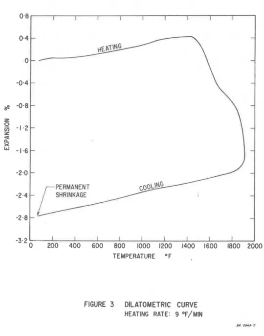
~ t u / l b " F(i) Dilatometric analysis: s e e F i g u r e 3.
(C)
Information concerning the components(I) Portland cement
Air -entr aining portland cement (supplied by St. M a r y ' s Cement Go. Ltd., 2221 Yonge St., Toronto) of specific s u r f a c e 4000 s q cm/g, a s m e a s u r e d with Blaine meter*.
(u)
R o t a r y kiln expanded shale aggregate ( a ) Origin:Shale deposit*:%. (b) Description:
Colour : 98 p e r cent grey, the r e m a i n d e r f r o m buff t o red**.
( c ) Conf ormance t o s o m e specification:
The m a t e r i a l conforms t o ASTM C331-53T (drying shrinkage t e s t was not performed)**.
*
This information h a s been supplied by H. I. King of DomtarConstruction M a t e r i a l s Ltd., in a l e t t e r dated F e b r u a r y 11, 1963, and a d d r e s s e d t o T. Z . Harmathy of Division of Building R e s e a r c h , National R e s e a r c h Council.
**
This information h a s been supplied by t h e Warnock H e r s e y Company Ltd.,
250 Madison Ave.,
Toronto 7, Ont.,
in a l e t t e r of June 6, 1961, signed by N. P. Henley, M. Ch. E., and confirmed byH. I. King of Domtar Coristruction Materials Ltd. in a l e t t e r of F e b r u a r y 11, 1963, a d d r e s s e d t o T. Z. Harmathy of Division of Building R e s e a r c h , National R e s e a r c h Council.
(d) Chemical analysis*: Compound P e r Cent by Wt SiOZ Fe203 A12°3 CaO MgO Alkali oxides S03 Water soluble m a t t e r 0. 30 L o s s on ignition 0.89 100.00
(e) Sieve analysis**: Sieve 3/8 in. No. 4 No. 8 No. 16 No. 30 No. 50 No. 100 No. 200 P e r centage P a s s i n g (aver age) (f) Unit weight**:
Damp loose: 46.9 lb/cu f t (average) Damp rodded: 56.6 lb/cu f t (average) D r y loose: 52.4 lb/cu ft (average) D r y rodded: 59.5 lb/cu f t (average) (g) Organic impurities (ASTM C40-56T) : Nil*.
*
T h i s information h a s been supplied by The Warnock H e r s e y Company Ltd., 250 Madison Ave., Toronto 7, Ont.., in a l e t t e r of June 6, 1961, signed by N. P. Henley, M. Ch. E., and confirmed by H.I.
King of Domtar Construction Materials Ltd. in a l e t t e r of F e b r u a r y 11, 1963, a d d r e s s e d t o T. Z. Harmathy of Division of Building Research,National R e s e a r c h Council.
**
This information h a s been supplied by Donald Inspection Limited,, 340 Richmond St. W.
,
Toronto, Ont.,
i n their r e p o r t No. T62-6439,(h) Unburned and underburned lumps (ASTM C142-55T): Nil'k;
5.
MortarThickness of m o r t a r layer: approximately 3/8 in. (A) General information
(a) Composition of mix:
P e r Cent by P e r Cent by Material Weight (aver age) volume Cement
Sand Water
(B) Mechanical and physical properties
(a) Density (in oven-dry condition): 106. 2 lb/cu ft. (b) Compressive strength: 786 lb/sq in. (average). (c) T h e r m a l conductivity (in oven-dry condition):
4. 79 ~ t u / h r s q ft"
i in.
a t88"
F.(d) Specific heat (in oven-dry condition): 0.200 ~ t u / l b "
F
a t 88" F.(C) Information concerning the components (I) Cement:
Masonry cement, CSA A8, type H, manufactured by St. Lawrence Cement Co.
(11) Sand:
No information available.
*
This information has been supplied by The Warnock H e r s e y Company Ltd., 250 Madison Ave., Toronto 7, Ont., in a letter of June 6, 1961, signed by N. P. Henley, M. Ch. E., and confirmed by H. I. King of Domtar Construction Materials Ltd. in a l e t t e r of F e b r u a r y 11, 1963, addressed t o T. Z. Harmathy of Division of Building Research, National R e s e a r c h Council.F i g u r e s 4 and 5 show the r e v e r s e and obverse s i d e s of
the specimen respectively p r i o r to the f i r e t e s t .
The specimen was of o r d i n a r y good workmanship. It had aged 128 days at the t i m e of the t e s t .
CONDITIONING OF TEST SPECIMEN
Since the m o i s t u r e content of the m a s o n r y units was too low during the construction, the t e s t specimen was moved into a
conditioning chamber where the t e m p e r a t u r e was maintained between 80 and 90" F, and t h e relative humidity between 90 and 100 p e r cent.
During t h e conditioning period the m o i s t u r e content and relative humidity (in the p o r e s ) of the m a s o n r y units w e r e m e a s u r e d at m o r e or l e s s regular intervals, in o r d e r to obtain information on the p r o g r e s s of m o i s t u r e adsorption. By means of a laboratory c o r e drill, cylindrical samples of about 7/8 in. diameter and 2.82 in. length w e r e taken f r o m the wall through the web of some m a s o n r y units. Each sample was divided into t h r e e s m a l l e r cylinders of about 0.94 in. length, which w e r e subsequently crushed into pieces not l a r g e r than 1/4 in. and analysed s e p a r a t e l y for relative
humidity and m o i s t u r e content. The relative humidity was m e a s u r e d by m e a n s of an "El-Tronicsl1 portable hygrometer (2).
The r e s u l t s of final humidity and m o i s t u r e analyses which w e r e c a r r i e d out the day before the f i r e t e s t , a r e shown in Table I.
TABLE I
MOISTURE CONTENT AND HUMIDITY O F MASONRY UNITS BEFORE THE E ' I R E TEST
Location Moisture content R e f e r r e d t o Oven-Dr y Weight, p e r cent Relative Humidity in the p o r e s , p e r cent 51. 5 68. 5 72. 5 I
Near outside surface At approximately 1. 4 in. f r o m outside s u r f a c e At c e n t r e of web I 2.8 5. 2 5. 5
The holes left in the m a s o n r y work after the removal of the cylindrical s a m p l e s w e r e filled with fast setting high-temperature m o r t a r .
TESTING PROCEDURE
The f i r e endurance t e s t was c a r r i e d out in accordance with ASTM ~ 1 1 9 - 6 1 . The furnace t e m p e r a t u r e was m e a s u r e d by nine s y m m e t r i c a l l y distributed t h e r h o c o u p l e s enclosed in 13/16 in. 0. D.
Inconel tubes of 0.035 in, wall thickness, the tubes equipped with carbon s t e e l cap a t the tip. The hot junction of the thermocouples was placed
6
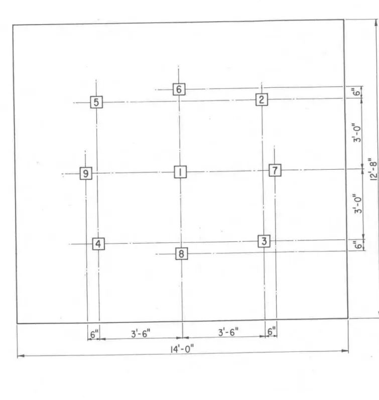
in. away from the exposed surface of the specimen. Both the individual t e m p e r a t u r e s at nine points of the furnace and t h e average of the nine t e m p e r a t u r e s w e r e recorded. The fuel input into t h e furnace was controlled in such a way t o make the average t e m p e r a t u r e follow the p r e s c r i b e d t e m p e r a t u r e v e r s u s t i m e curve.The t e m p e r a t u r e of the unexposed surface of the specimen was m e a s u r e d by nine thermocouples covered with standard asbestos pads, 6 in. s q u a r e and 0. 4 in. in thickness symmetrically distributed a s shown in F i g u r e 6.
During the t e s t the specimen c a r r i e d a v e r t i c a l load of
80 lb/sq in. ( r e f e r r e d t o g r o s s sectional a r e a ) applied by 8 hydraulic jacks. The specimen was not r e s t r a i n e d along the v e r t i c a l edges.
The l a t e r a l deflection a t t h r e e points of the specimen was observed and recorded. The sketch i n F i g u r e 8 shows how the various deflection m e a s u r e m e n t s should b e interpreted.
A detailed description of t h e f i r e t e s t facilities of the National R e s e a r c h Council i s available ( 3 ) .
RESULTS
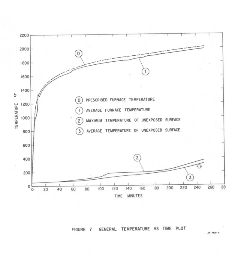
The variation of the average t e m p e r a t u r e of the furnace is shown in F i g u r e 7. The uniformity of the furnace t e m p e r a t u r e was v e r y good. After 10-min run t h e maximum local deviation from the average t e m p e r a t u r e was always l e s s than 11 5°F.
The average and the maximum unexposed s u r f a c e
t e m p e r a t u r e s a r e a l s o plotted in F i g u r e 7. The point 'of failure i s indicated by an arrow. The failure was due t o the average
t e m p e r a t u r e of the unexposed surface exceeding t h e allowable limit (in t h i s c a s e 50
+
250 = 300°F) and o c c u r r e d at 4 h r 3 min.The deflection measurements a r e plotted in Figure 8. Cracking of the specimen s t a r t e d , a t a fairly e a r l y stage. The f i r s t crack on t h e unexposed surface developed from top t o bottom after 8-min run. Within an hour two other s i m i l a r c r a c k s had developed. At 3 h r 5 min, the glow of furnace could be seen through one of the cracks. The t e m p e r a t u r e was checked over and in the vicinity of t h i s c r a c k by means of a roving thermocouple was found t o be lower than the allowable limit (50
+
325=
375" F).Immediately after reaching the point of failure the furnace was opened and the specimen subjected t o a 79 min hose s t r e a m test. The water p r e s s u r e at the base of the nozzle was 45 lb/sq in.
gauge, a s specified by ASTM E 119-61. Figure 9 shows the exposed surface of the specimen immediately before and Figure 10 a few minutes after the application of the stream. It i s seen that a layer of roughly 5/8 in. thickness was washed off from the surface.
Twenty-four hours after the completion of the t e s t s the specimen was reloaded. The load was gradually increased. The specimen collapsed at 158 lb/sq in. superimposed load ( r e f e r r e d t o g r o s s sectional a r e a ) which is slightly lower than that specified by ASTM E119-61 (twice the load exerted during the f i r e t e s t
=
160 lb/ s q in.). Figure 11 shows the collapsing specimen.CONCLUSION
A t e s t specimen of a load-bearing wall built from masonry units (89. 1 p e r cent solid) of r o t a r y kiln expanded shale aggregate and of
6
in. by 8 in. by 16 in. nominal sizes, was subjected t o standard f i r e endurance, hose s t r e a m and reload t e s t s , specified by ASTM E 119-61,
on 1 November, 1962. The' specimen yielded a f i r e endurance of 4 h r 3 min. The failure was due t o the average t e m p e r a t u r e of the unexposed s u r f a c e exceeding the allowable limit,300°F in this case. The specimen collapsed during the reload test. According t o ASTM E119-61 the f i r e t e s t can be regarded as successful for a period of 4 h r 3 min, i f the specimen is subjected t o a superimposed load not higher than 79 lb/sq in. ( r e f e r r e d t o
REFERENCES
1. "Fiberfrax Ceramic Fiber". Pamphlet issued by The
Carborundum Company, Research and Development Division, Niagar a Falls, N. Y.
2. "El-Tronics Portable Hygrometer, Operating and Maintenance
Manual, Model 103". Pamphlet issued by El-Tronics Inc.
,
Philadelphia,. Pa.3. G. W. Shorter and T. 2. Harmathy. F i r e Research Furnaces at the National R e s e a r c h Council, National Research Council, Division of Building Research; F i r e Study No. 1, Ottawa, July
1960
(NRC 5732).FIGURE 3 DILATOMETRIC CURVE
Figure 4
Reverse side of the specimen prior t o rfire test
I
"'P
I Figure 5
Obverse side of the I specimen prior to
@
PRESCRIBED FURNACE TEMPERATURE@
AVERAGE FURNACE TEMPERATURE@
MAXIMUM TEMPERATURE OF UNEXPOSED SURFACE@
AVERAGE TEMPERATURE OF UNEXPOSED SURFACETIME MINUTES
. ..
\
x 24 HOURS LATER \
'x
1
TIME MINUTES
Figure
9
Exposed surface of the specimen after the fire test, prior to hose stream test
Figure 10
Exposed surface of the specimen a few minutes after hose stream test
Figure 1 1
Collapse of the