HAL Id: hal-02104053
https://hal.archives-ouvertes.fr/hal-02104053
Submitted on 19 Apr 2019HAL is a multi-disciplinary open access archive for the deposit and dissemination of sci-entific research documents, whether they are pub-lished or not. The documents may come from teaching and research institutions in France or abroad, or from public or private research centers.
L’archive ouverte pluridisciplinaire HAL, est destinée au dépôt et à la diffusion de documents scientifiques de niveau recherche, publiés ou non, émanant des établissements d’enseignement et de recherche français ou étrangers, des laboratoires publics ou privés.
Chiral Optical Stern-Gerlach Newtonian Experiment
Nina Kravets, Artur Aleksanyan, Etienne Brasselet
To cite this version:
Nina Kravets, Artur Aleksanyan, Etienne Brasselet. Chiral Optical Stern-Gerlach Newtonian Ex-periment. Physical Review Letters, American Physical Society, 2019, 122 (2), pp.024301 (1–). �10.1103/PhysRevLett.122.024301�. �hal-02104053�
Chiral Optical Stern-Gerlach Newtonian Experiment
Nina Kravets, Artur Aleksanyan, and Etienne Brasselet*
Universit´e de Bordeaux, CNRS, Laboratoire Ondes et Mati`ere d’Aquitaine, F-33400 Talence, France (Received 28 August 2018; revised manuscript received 6 November 2018; published 16 January 2019)
We report on a chiral optical Stern-Gerlach experiment where chiral liquid crystal microspheres are selectively displaced by means of optical forces arising from optical helicity gradients. The present Newtonian experimental demonstration of an effect predicted at molecular scale [New J. Phys. 16, 013020 (2014)] is a first instrumental step in an area restricted so far to theoretical discussions. Extending the Stern-Gerlach experiment legacy to chiral light-matter interactions should foster further studies, for instance towards the elaboration of chirality-enabled quantum technologies or spin-based optoelectronics.
DOI:10.1103/PhysRevLett.122.024301
The century-old Stern-Gerlach experiment[1]is not only one of the few canonical quantum physics experiments but also a paradigm when dealing with state-selective deflec-tions of particles in a field gradient. In particular, optical analogs of Stern-Gerlach experiments emerged after the advent of the laser[2]and were further enriched by versatile light-matter interaction processes[3–5]. In the multidisci-plinary context of sorting chiral entities with opposite handedness, contactless optical Stern-Gerlach approaches have been proposed[6–9], however, without experimental realization to date. Chirality refers to mirror-image entities (enantiomers) that cannot be superimposed by spatial rotations, which dates back almost two centuries ago with the pioneering works of several scientists. In particular, Louis Pasteur, who performed the first chiral resolution— the process of separating a pair enantiomers—of racemic acid using handmade tweezers to sort crystallites of opposite handedness[10]. Since then, the concept of chirality does not only hold a special place in chemistry but spreads across scientific disciplines like biology, mathematics, and physics. Nowadays, the need for enantiomers separation is a cornerstone of pharmaceutical and food-processing indus-tries as well as a key ingredient for carbon- and DNA-based technologies[11]. In this context, chiral light emerged as a novel tool to achieve contactless chiral resolution as theoretically discussed by several groups [6–9,12–23]. While some of the proposed approaches have been exper-imentally addressed at the microscale [24–28], others remain elusive, such as those relying on chirality-selective lateral forces. This is the case of an intriguing chiral optical analog of the Stern-Gerlach experiment for which a chiral entity is selectively displaced along a one-dimensional (1D) gradient of optical helicity [9]. Here we report on the experimental proof of concept of an optical Stern-Gerlach chiral sorter operated in the classical regime, where the particle’s deflection is described by Newtonian mechanics. In our experiments, a light field with a 1D gradient of helicity density is prepared according to Ref. [29], by
interfering two slightly noncollinear laser beams having orthogonal linear polarization states. This is made by using an optical element called a “wedge depolarizer,” which consists of a quartz wedge having its optical axis oriented along the wedge slope that defines the x axis, cemented to a fused silica wedge to compensate for the overall deviation of the light flow. Indeed, by illuminating the depolarizer by a normally incident (along the z axis) linearly polarized continuous-wave Gaussian beam at λ0¼ 532 nm
wave-length with a polarization azimuth oriented at 45° from the x axis, the collinear ordinary and extraordinary waves propagating along the z axis in the quartz wedge are refracted at the quartz-silica interface into two noncollinear beams making an angle α∼ 2 mrad one with another. Such a single-mirror approach has the advantage to be resilient to mechanical vibrations, in contrast to a conventional two-mirror interference scheme. By imaging the plane of the depolarizer with a microscope objective, we thus produce a spatially oscillating helicity density along the x axis with a spatial period Λ ¼ λ0=α≃ 200 μm in the plane of the
sample. Moreover, in order to ensure practically that the chiral micro-objects with characteristic size R are confined to motion along the direction of the helicity gradients, we use a Gaussian light field having an optical intensity spatial distribution of the form Iðx;yÞ ¼ I0exp½−2ðx2=w2xþ
y2=w2
yÞ& where I0¼ 2P=ðπwxwyÞ with P is the total optical
power, with R∼ wy≪ wx. This is made by placing the
depolarizer in the focal plane of a cylindrical lens. We refer to the Supplemental Material[30]for a detailed version of the setup depicted in Fig.1(a).
The assessment of the helicity density h is made account-ing that α≪ 1 and our paraxial framework. In that case, one can consider that hðx; yÞ ∝ S3ðx; yÞ ¼ ˜hðx; yÞ where S3¼
IL− IR is the third Stokes parameter with IL;R being the
intensity distributions of the left-handed and right-handed circularly polarized component of the spatially modulated optical field in the plane of the sample[29]. Measurement of
the 1D modulation of the helicity along the x axis is shown in Fig.1(c)(thick curve), which reveals a behavior of the form ˜hðx;0Þ¼I0sinð2πx=ΛÞexpð−2x2=w2xÞ (thin curve),
noting that the depolarizer is appropriately positioned along the x axis to ensure a maximal helicity gradient at the centroid location of the driving light beam that defines the origin ðx; yÞ ¼ ð0; 0Þ.
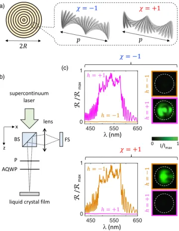
We use chiral droplets made of both right-handed ðχ ¼ þ1Þ and left-handed ðχ ¼ −1Þ helix-based liquid crystal commercial mixtures (BEAM Co.) characterized by a helical pitch p. The droplets are prepared by dispersing the liquid crystal into a∼40 wt% aqueous glycerol solution doped with ∼1 wt% polyvinyl alcohol. This leads to the spontaneous formation of spherical droplets having radial distribution of the helix axis. The resulting onionlike structure of the droplets is depicted in Fig. 2(a). The prepared fluidic mixture is then inserted into a cell made of two glass substrates separated by a∼200 μm gap and a hydrophilic surface treatment is made to prevent the droplet from wetting the bottom glass substrate. From the optics of chiral anisotropic media, light propagating along the helix axis is fully transmitted when hχ ¼ þ1. On the other hand, when hχ ¼ −1, light experiences the circular Bragg reflection phenomenon [32], which is associated with a photonic band gap defined by pn⊥< λ < pnk, nkand n⊥ being the refractive indices along and perpendicular to the liquid crystal molecular orientation. This behavior is assessed using the setup sketched in Fig.2(b). The average
reflection spectra of reference cholesteric films are shown in Fig.2(c)for the four combinations ðχ; hÞ ¼ ð'1; '1Þ.
Prior to recording the light-induced motion of each studied droplet, its handedness is qualitatively identified in situ via its reflection image at 532 nm. This is done by introducing a reflective branch equivalent to Fig.2(b)to the main setup sketched in Fig. 2(a); typical images are shown in the rightmost part of Fig.2(c). Since λ0falls into the circular
photonic band gap, strong chiral-selective light-matter interaction is achieved by design.
Summarizing, the analogy between the original Stern-Gerlach experiment and ours is as follows: the liquid crystal
(a)
(b)
(c)
FIG. 1. (a) Sketch of the setup. Q and S, respectively, refer to cemented quartz crystal (double arrow shows the optical axis orientation) and silica wedges. The incident laser beam is linearly polarized at 45° from the x axis. (b) Optical intensity distribution in the plane of the sample having an elliptical Gaussian shape associated with waists radii at expð−2Þ of the maximal intensity wx¼ 700 μm and wy¼ 20 μm along the x and y axes. (c) 1D
reduced harmonic optical helicity ˜hðx; 0Þ=Iðx; 0Þ in the plane of the sample, with spatial period Λ ≃ 200 μm. Thick red curve: Experimental data obtained by spatial averaging along the y axis in the range −wy=2 < y < wy=2. Thin dark curve: Expected
sinusoidal behavior.
(a)
(b)
(c)
FIG. 2. (a) Onionlike chiral liquid crystal droplet where the layered structure refers to the periodic modulation of the dielectric permittivity tensor of the liquid crystal with the period being half the helical pitch p of the supramolecular helix organization, see Ref.[31]for a detailed structural description. (b) Sketch of the spectroscopic setup. BS: beam splitter; P: linear polarizer; AQWP: achromatic quarter-wave plate. FS: fiber spectrometer. (c) For each of the four combinations ðχ; hÞ ¼ ð'1; '1Þ, the reflection spec-trum for a 8 μm-thick film of the liquid crystal mixture with uniform alignment of helical axis along the normal to the film is shown (left panel) as well as the polarized reflection image, at 532 nm, of a droplet with radius R≃ 30 μm (right panel, where the contour of the droplet appear as a white dashed circle). Every spectrum is the average of five independent measurements and is normalized by the spectrum obtained from the Fresnel reflection from a bare glass substrate, while Rmax refers to the maximal
reflectance of the whole set of measured spectra.
droplets play the role of the silver atoms, the handedness of the droplets plays the role of the spin of the silver atoms, and the optical helicity gradient plays the role of magnetic field gradient. A practical technical difference is that we observe displacements rather than deflection. Note such a framework originality in the context of previous realiza-tions of Stern-Gerlach analogs where light can play either the role of the field gradient [3], that of the deflected particles [4], or even both [5].
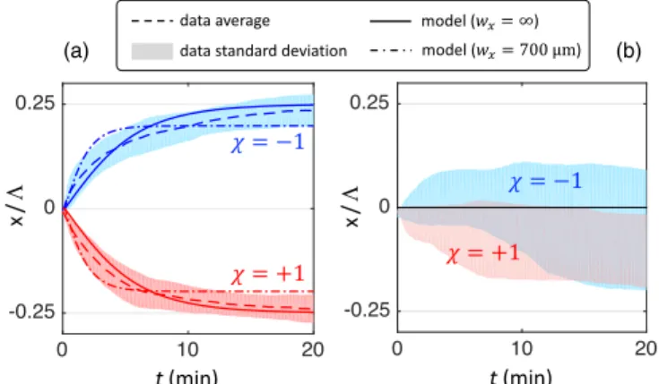
Our experimental protocol consists in placing a chiral droplet with radius R≃ 30 μm at ðx; yÞ ¼ ð0; 0Þ and recording its trajectory under constant irradiation. The qualitative demonstration is reported in Fig. 3 where images of the droplet at t ¼ 0 and after 20 min, for which the steady state is reached, are shown both for left-handed [Fig. 3(a)] and right-handed [Fig. 3(b)] droplets. The observed light-induced transverse displacements along the x axis have opposite sign and final states are located nearby x ¼ 'Λ=4, where the gradient of helicity vanishes [Fig. 1(c)]. On the other hand, quantitative analysis is assessed by retrieving the droplet trajectories from the recorded data. The results are illustrated in Fig.4(a)which presents the average trajectory and standard deviation associated with measurements made over∼10 independent events made with different droplets of approximately same radius, both for χ ¼ '1. Chiral-selective transverse deviation under the helicity gradient is therefore clearly demonstrated experimentally. In contrast, no clear discrimi-natory trend is observed in the control experiment without helicity gradients (this is made by removing the depolar-izer), as shown in Fig. 4(b).
The quantitative support is provided from chiral Bragg droplet optomechanics knowledge. Indeed, the vectorial force field can be calculated from a simplified ray-optics model according to Ref. [28]. The latter model is written for axisymmetric beams illuminating a droplet, from which
one can derive the expressions for the lateral optical force field in the plane ðx; yÞ, F ¼ Fxx þ Fyy. In short, the
model consists in summing up the elementary contributions of the linear momentum transfer at the surface of the droplet. The droplet is associated with the usual polar and azimuthal angles ðθ; ϕÞ in the spherical coordinate origi-nating at the droplet center, noting that θ ¼ 0 points towards the beam propagation direction (i.e., the z axis). A key parameter is the angle ϑB[33]that characterizes the
ability of the chiral liquid crystal to reflect light via the circular Bragg reflection phenomenon. Namely, if an incident ray impinges at the surface of the droplet with a local incidence angle lower than ϑBthe light is considered
totally reflected if h ¼ −χ while all other situations are treated as if the droplet is a dielectric sphere with refractive index n ¼ ðnkþ n⊥Þ=2 being the mean of the refractive
index parallel and perpendicular to the liquid crystal main molecular axis. The result of calculations for χ ¼ −1 is Fðx; yÞ ¼ −next2cR2 !Z 2π 0 Z π−ϑ B π=2 fIðX; YÞfðθÞ
× ½cos ϕx þ sin ϕy& sin 2θgdθdϕ þ
Z 2π
0
Z π
π−ϑB
fIðX; YÞ½SðXÞfðθÞ þ CðXÞ sin 2θ&
× ½cos ϕx þ sin ϕy& sin 2θgdθdϕ "
: ð1Þ
next is the refractive index of the outer fluid, c is the speed
of light,
(a) (b)
FIG. 3. Direct observation of chiral-selective displacement under an optical helicity gradient illustrated by snapshots of an irradiated droplet with radius R≃ 30 μm initially placed at x ¼ 0 at time t ¼ 0 and after 20 min illumination by the laser beam with space-varying helicity and total optical power P ¼ 400 mW, for χ ¼ −1 (a) and χ ¼ þ1 (b). The dashed white circle refers to the contour of the droplet.
(a) (b)
FIG. 4. Quantitative analysis of chiral-selective displacement by discriminatory lateral optical forces illustrated by the dis-placement dynamics over 20 min duration illumination. (a) Dis-criminatory dynamics for the same conditions as in Fig. 3. Dashed curves refer to the average over ∼10 independent measurements and colored bands refer to the corresponding standard deviation. Solid lines: Simulations according to the model discussed in the text. Blue color: χ ¼ −1; red color: χ ¼ þ1. (b) Control experiment using a uniform linearly polar-ized with null helicity, all other parameters being the same as in panel (a).
Xðx; θ; ϕÞ ¼ x þ R sin θ cos ϕ; ð2Þ Yðy; θ; ϕÞ ¼ y þ R sin θ sin ϕ; ð3Þ SðXÞ ¼ sin2ðπX=Λ þ π=4Þ; ð4Þ
CðXÞ ¼ cos2ðπX=Λ þ π=4Þ; ð5Þ
and
fðθÞ ¼ R sin 2θ − T2sinð2θ − 2θintÞ þ R sin 2θ
1þ 2R cos 2θintþ R2
; ð6Þ
where R and T ¼ 1 − R are the reflectance and transmittance of the droplet interface, with θint¼
− arcsin½ðnext=nÞ sin θ& the signed angle of refraction.
Accounting for the incident circular polarization state and discarding the polarization projection on the local frame of incidence, we also assume that RðθÞ ¼ ½RkðθÞ þ
R⊥ðθÞ&=2 with RkðθÞ ¼ ½tanðθ − θintÞ= tanðθ þ θintÞ&2
and R⊥ðθÞ ¼ ½sinðθ − θintÞ= sinðθ þ θintÞ&2the reflectance
coefficients of plane waves polarized parallel and perpendicular to the incidence plane [34]. For χ ¼ þ1,
one simply needs to make the formal change S ↔ C in Eq.(1).
The parameters entering in the simulations are chosen according to what follows. Namely, the refractive index of the≃40 wt % aqueous glycerol solution doped with 1 wt % polyvinyl alcohol is taken as next≃ 1.38 from the tabulated
data of aqueous glycerol mixture at 20 °C and 589 nm wavelength and its dynamic viscosity as η ¼ 3.72 mPa s
[35]. The used optical power is P ¼ 400 mW, and we use
wx¼ 700 μm and wy¼ 20 μm. The average refractive
index n of the liquid crystal mixture is evaluated from the optics of circular Bragg reflection that gives Δλ ¼ pðnk− n⊥Þ for the circular photonic band gap width.
Indeed, we measureΔλ ≃ 100 nm [Fig.2(c)] and the liquid crystal data sheet gives the birefringence nk− n⊥ ¼ 0.343 at 532 nm wavelength and room temperature. This gives p≃ 290 nm. The central wavelength of the band gap equals np≃ 530 nm, which gives n ≃ 1.82. This leaves the characteristic Bragg angle ϑB as the single adjustable
parameter of the model.
The dynamics of the droplets is theoretically retrieved from Newtonian mechanics, noting that the Reynolds number associated with the fluid flow around the moving droplet is small with respect to unity. This implies that the drag viscous force (Fdrag) exerted on the droplet in a
direction opposite to its displacement is balanced by the optical force Fx. Since Fdrag¼ 6πηRð∂x=∂tÞ, one gets
xðtÞ ¼Rt
0Fx(xðt0Þ; 0)=ð6πηRÞdt0. By minimizing the
stan-dard deviation between simulations (dash-dotted curve) and experimental data (dashed curve) over the full dynam-ics, see Fig.4(a), one obtains ϑB≃ 19°. The corresponding
force field exerted on the droplets in the plane ðx; yÞ is shown in Fig.5where the x and y contributions, namely, Fx
and Fy, are displayed. The 1D displacement along the
x axis irrespective of the material chirality is explained by the fact that Fy acts as restoring force towards y ¼ 0 at all
times, both for ∂h=∂x ≠ 0 [Fig. 5(a)] and ∂h=∂x ¼ 0 [Fig. 5(b)]. In the presence of the helicity gradient, the spatially modulated Fxcomponent is maximal at the origin,
its sign is that of χð∂h=∂xÞ and its magnitude vanishes at jx∞j ≲ Λ=4, which corresponds to the asymptotic location
of the droplet. The slight offset between x∞and the location of zero helicity is due to the nonvanishing restoring contribution towards the origin due to the finite value of wx. However, one notes that imposing wx →∞ gives even
better agreement between simulations and observations, see solid curve in Fig.4(a)for which ϑB≃ 15°. This is ascribed
to the residual intensity modulation along the x axis that practically washes out the intensity gradient force contri-bution along this axis. Finally, in the absence of a helicity gradient, both Fx and Fy are null at the origin, which
subsequently corresponds to a 2D optical trapping con-figuration. Still, uncontrolled random drift of the droplets is observed [Fig. 4(b)]. It is associated with an average maximal velocity much weaker than in the case∂h=∂x ≠ 0. This is ascribed to the fact that residual contributions (residual flows, temperature gradients, mechanical vibra-tions, spatial noise of the intensity profile, etc.) are at work
(a)
(b)
FIG. 5. Calculated maps of the x and y components of the optical force field exerted on the droplet, Fxand Fy, in the plane
ðx; yÞ for χ ¼ '1, in the presence (a) and absence (b) of a helicity gradient using all experimental values for all the model param-eters and ϑB≃ 19° from the adjustment described in the text.
Straight cross markers indicate the origin, where the droplet is placed at t ¼ 0. Oblique cross markers in panel (a) indicate the asymptotic position of the droplet after 20 min.
when ∂h=∂x ¼ 0, while the droplets remain confined to motion along the x axis owing to intensity gradient forces along the y axis. We also note that the slight imbalance (regarding the material handedness) is perhaps due to not perfectly sufficient statistics.
These results invite for further tests of recent theoretical efforts regarding chiral light-matter interaction [36–42]. Since chirality is perceived as a key actor towards answer-ing universal questions such as the prevalence of a given handedness in living systems [43] or implementing non-reciprocal photonics technologies [44,45], present work calls for chiral optomechanics developments, such as chiral resolution, especially at the nanoscale, where quantum effects come to prominence. Finally, noting that the Stern-Gerlach experiment has inspired many branches of physics, for instance astrophysics with the quest for hypothetical elementary particles[46], our work exemplifies that anal-ogy remains a powerful tool worth considering on exper-imental grounds.
We thank J. Leng for the hydrophilic agent Mirapol Surf S 500 used to treat the bottom glass substrates. This study has been carried out with financial support from the French National Research Agency (ANR) in the frame of the “Investments for the future” Programme IdEx Bordeaux LAPHIA (ANR-10-IDEX-03-02).
*etienne.brasselet@u-bordeaux.fr
[1] W. Gerlach and O. Stern, Der experimentelle nachweis der richtungsquantelung im magnetfeld,Z. Phys. 9, 349 (1922). [2] A. Kazantsev, Recoil effect in a strong resonant field, Zh. Eksp. Teor. Fiz. 67, 1660 (1974) [Sov. Phys. JETP 40, 825 (1975)].
[3] T. Sleator, T. Pfau, V. Balykin, O. Carnal, and J. Mlynek, Experimental Demonstration of the Optical Stern-Gerlach Effect,Phys. Rev. Lett. 68, 1996 (1992).
[4] L. Karpa and M. Weitz, A Stern-Gerlach experiment for slow light,Nat. Phys. 2, 332 (2006).
[5] A. Karnieli and A. Arie, All-Optical Stern-Gerlach Effect, Phys. Rev. Lett. 120, 053901 (2018).
[6] Y. Li, C. Bruder, and C. Sun, Generalized Stern-Gerlach Effect for Chiral Molecules, Phys. Rev. Lett. 99, 130403 (2007).
[7] B. Spivak and A. Andreev, Photoinduced Separation of Chiral Isomers in a Classical Buffer Gas,Phys. Rev. Lett. 102, 063004 (2009).
[8] X. Li and M. Shapiro, Theory of the optical spatial separation of racemic mixtures of chiral molecules,J. Chem. Phys. 132, 194315 (2010).
[9] R. P. Cameron, S. M. Barnett, and A. M. Yao, Discrimina-tory optical force for chiral molecules, New J. Phys. 16, 013020 (2014).
[10] L. Pasteur, Recherches sur les relations qui peuvent exister entre la forme cristalline, la composition chimique et le sens de la polarisation rotatoire, Ann. Phys. Chem. 24, 442 (1848).
[11] J. Zhang, M. T. Albelda, Y. Liu, and J. W. Canary, Chiral nanotechnology,Chirality 17, 404 (2005).
[12] A. Canaguier-Durand, J. A. Hutchison, C. Genet, and T. W. Ebbesen, Mechanical separation of chiral dipoles by chiral light,New J. Phys. 15, 123037 (2013).
[13] D. S. Bradshaw and D. L. Andrews, Chiral discrimination in optical trapping and manipulation,New J. Phys. 16, 103021 (2014).
[14] S. B. Wang and C. T. Chan, Lateral optical force on chiral particles near a surface, Nat. Commun. 5, 3307 (2014).
[15] A. Hayat, J. B. Mueller, and F. Capasso, Lateral chirality-sorting optical forces, Proc. Natl. Acad. Sci. U.S.A. 112, 13190 (2015).
[16] M. H. Alizadeh and B. M. Reinhard, Transverse chiral optical forces by chiral surface plasmon polaritons, ACS Photonics 2, 1780 (2015).
[17] A. Canaguier-Durand and C. Genet, Plasmonic lateral forces on chiral spheres,J. Opt. 18, 015007 (2016).
[18] H. Chen, C. Liang, S. Liu, and Z. Lin, Chirality sorting using two-wave-interference-induced lateral optical force, Phys. Rev. A 93, 053833 (2016).
[19] Y. Zhao, A. A. Saleh, and J. A. Dionne, Enantioselective optical trapping of chiral nanoparticles with plasmonic tweezers,ACS Photonics 3, 304 (2016).
[20] T. Zhang, M. R. C. Mahdy, Y. Liu, J. H. Teng, C. T. Lim, Z. Wang, and C.-W. Qiu, All-optical chirality-sensitive sorting via reversible lateral forces in interference fields,ACS Nano 11, 4292 (2017).
[21] P. Acebal, L. Carretero, and S. Blaya, Design of an optical conveyor for selective separation of a mixture of enantiom-ers,Opt. Express 25, 32290 (2017).
[22] T. Cao and Y. Qiu, Lateral sorting of chiral nanoparticles using fano-enhanced chiral force in visible region, Nano-scale 10, 566 (2018).
[23] G. Pellegrini, M. Finazzi, M. Celebrano, M. A. Iatì, O. M. Maragò, P. Biagioni et al., Superchiral surface waves for all-optical enantiomer separation,arXiv:1803.10010.
[24] R. J. Hernandez, A. Mazzulla, A. Pane, K. Volke-Sepulveda, and G. Cipparrone, Attractive-repulsive dynam-ics on light-responsive chiral microparticles induced by polarized tweezers,Lab Chip 13, 459 (2013).
[25] G. Tkachenko and E. Brasselet, Spin Controlled Optical Radiation Pressure,Phys. Rev. Lett. 111, 033605 (2013). [26] G. Tkachenko and E. Brasselet, Optofluidic chiral sorting of
material chirality by chiral light, Nat. Commun. 5, 3577 (2014).
[27] M. Donato, J. Hernandez, A. Mazzulla, C. Provenzano, R. Saija, R. Sayed, S. Vasi, A. Magazzu, P. Pagliusi, R. Bartolino, P. Gucciardi, O. Marago, and G. Cipparrone, Polarization-dependent optomechanics mediated by chiral microresonators,Nat. Commun. 5, 3656 (2014).
[28] G. Tkachenko and E. Brasselet, Helicity-dependent three-dimensional optical trapping of chiral microparticles,Nat. Commun. 5, 4491 (2014).
[29] R. P. Cameron, S. M. Barnett, and A. M. Yao, Optical helicity of interfering waves,J. Mod. Opt. 61, 25 (2014). [30] See Supplemental Material at http://link.aps.org/
supplemental/10.1103/PhysRevLett.122.024301 for a de-tailed version of the setup depicted in Fig. 1(a).
[31] D. Sec, T. Porenta, M. Ravnik, and S. Zumer, Geometrical frustration of chiral ordering in cholesteric droplets, Soft Matter 8, 11982 (2012).
[32] M. Faryad and A. Lakhtakia, The circular bragg phenome-non,Adv. Opt. Photonics 6, 225 (2014).
[33] Note that the angle ϑBrefers to the angle labeled θext;B in
Ref.[28].
[34] M. Born and E. Wolf, Principles of Optics (Pergamon, New York, 2005).
[35] Glycerine Producers’ Association, Physical Properties of Glycerine and Its Solutions (Glycerine Producers’ Associ-ation, New York, 1963), p. 13.
[36] M. Nieto-Vesperinas, J. J. Saenz, R. Gomez-Medina, and L. Chantada, Optical forces on small magnetodielectric particles,Opt. Express 18, 11428 (2010).
[37] K. Y. Bliokh, Y. S. Kivshar, and F. Nori, Magnetoelectric Effects in Local Light-Matter Interactions,Phys. Rev. Lett. 113, 033601 (2014).
[38] A. Canaguier-Durand and C. Genet, Chiral route to pulling optical forces and left-handed optical torques,Phys. Rev. A 92, 043823 (2015).
[39] I. Fernandez-Corbaton, M. Fruhnert, and C. Rockstuhl, Objects of Maximum Electromagnetic Chirality,Phys. Rev. X 6, 031013 (2016).
[40] R. P. Cameron, J. B. Götte, S. M. Barnett, and A. M. Yao, Chirality and the angular momentum of light,Phil. Trans. R. Soc. A 375, 20150433 (2017).
[41] F. Alpeggiani, K. Y. Bliokh, F. Nori, and L. Kuipers, Electromagnetic Helicity in Complex Media, Phys. Rev. Lett. 120, 243605 (2018).
[42] D. L. Andrews, Quantum formulation for nanoscale optical and material chirality: Symmetry issues, space and time parity, and observables, J. Opt. 20, 033003 (2018).
[43] I. Myrgorodska, C. Meinert, S. V. Hoffmann, N. C. Jones, L. Nahon, and U. J. Meierhenrich, Light on chirality: Absolute asymmetric formation of chiral molecules relevant in prebiotic evolution, ChemPlusChem 82, 74 (2017).
[44] P. Lodahl, S. Mahmoodian, S. Stobbe, A. Rauschenbeutel, P. Schneeweiss, J. Volz, H. Pichler, and P. Zoller, Chiral quantum optics,Nature (London) 541, 473 (2017). [45] M. Schäferling, Chiral Nanophotonics (Springer International
Publishing, Switzerland, 2017).
[46] D. Chelouche and E. I. Guendelman, Cosmic analogs of the Stern-Gerlach experiment and the detection of light bosons, Astrophys. J. 699, L5 (2009).
SUPPLEMENTARY INFORMATION
A chiral optical Stern-Gerlach Newtonian experiment
Nina Kravets, Artur Aleksanyan, and Etienne Brasselet*
November 6, 2018
Univ. Bordeaux, CNRS, Laboratoire Ondes et Mati`ere d’Aquitaine, F-33400 Talence, France. *Corresponding author: etienne.brasselet@u-bordeaux.fr
Glan prism Half-wave plate Cylindrical lens f=200mm Wedge depolarizer (WDPOL-A, Thorlabs : cemented quartz and silica wedges). This element is removed for the control experiment. 4x objective (NA=0.1) sample Beam splitter circular polarizer 10x objective (NA=0.25) Optical attenuator Circular polarizer (activated for helicity measurement) Camera 1 Half-wave plate Camera 2 lens f=200mm z y x Elements on flip mounts Experimental parameters in the sample plane: wx= 700 µm wy= 20 µm P = 400 mW R = 30 µm L = 200 µm activated for reflection circularly polarized imaging of the droplet Continuous-wave collimated laser beam at 532 nm wavelength