Development of a Verification and Validation
Framework for Autonomous Soft-Docking of
Spacecraft with Uncertain Dynamic Properties
by
Jillian Melanie James
S.B. Aerospace Engineering,
Massachusetts Institute of Technology (2010)
Submitted to the Department of Aeronautics and Astronautics
in partial fulfillment of the requirements for the degree of
Master of Science in Aeronautics and Astronautics
at the
MASSACHUSETTS INSTITUTE OF TECHNOLOGY
June 2016
c
○
Massachusetts Institute of Technology 2016. All rights reserved.
Author . . . .
Department of Aeronautics and Astronautics
May 19, 2016
Certified by. . . .
David W. Miller
Professor of Aeronautics and Astronautics
Thesis Supervisor
Certified by. . . .
Alvar Saenz-Otero
Director, Space Systems Laboratory
Thesis Supervisor
Accepted by . . . .
Paulo C. Lozano
Chair, Graduate Program Committee
Development of a Verification and Validation Framework for
Autonomous Soft-Docking of Spacecraft with Uncertain
Dynamic Properties
by
Jillian Melanie James
Submitted to the Department of Aeronautics and Astronautics on May 19, 2016, in partial fulfillment of the
requirements for the degree of
Master of Science in Aeronautics and Astronautics
Abstract
Although soft-docking in space has been demonstrated in the past, these missions have required detailed information about the target vehicle for success, and often relied on manual control during the final stages. Autonomous docking, however, shows the potential to greatly reduce operation costs while accomplishing complex scenarios. Unfortunately, unknown dynamics and changing parameters stress current attitude control systems for docking applications such as spacecraft servicing, debris capture, and space robotics operations. Adaptation for example may assist with vehicle control under such conditions, however requires careful validation.
Since autonomous soft-docking has limited heritage when there are system uncer-tainties, risk reduction prior to operation becomes very important for mission success. In this thesis a verification and validation framework was developed for autonomous soft-docking of spacecraft under such uncertainties. The approach combines risk-management techniques, simulation, Monte Carlo analysis, diagnostic tools and ex-perimentation in the micro-gravity environment of the International Space Station (ISS) to create a comprehensive risk-reduction strategy. Development methods are described to provide general guidelines for design of future soft-docking missions.
Additionally, this thesis explores how such verification and validation methods may be used to assess how an adaptive controller can maintain attitude control au-thority when a spacecraft joins with an object with limited physical parameter in-formation. The goal is to chart a path for controller validation via future spaceflight experimentation. The risk reduction framework and controller analyses and tests are based on working with the Synchronized Position Hold Engage Reorient Experimental Satellite (SPHERES) facility at MIT and on the ISS.
Thesis Supervisor: David W. Miller
Thesis Supervisor: Alvar Saenz-Otero Title: Director, Space Systems Laboratory
Disclaimer: This material is based upon work supported by the United States Air Force under Air Force Contract No. FA8721-05-C-0002 and/or FA8702-15-D-0001. Any opinions, findings and conclusions or recommendations expressed in this material are those of the author and do not necessarily reflect the views of the United States Air Force.
Acknowledgments
There are so many kind people who have helped me along the way, and I am grateful for every one of them.
I thank my advisor Professor David Miller for his unfailing confidence in by aca-demic abilities, and dedication to ensuring my ultimate success in this program. I would also like to thank Dr. Alvar Saenz-Otero for his guidance and support through-out my research, and Dr. Danilo Roascio for his direction in technical matters. I would also like to acknowledge the influence of Professor Anuradha Annaswamy, Professor Sertac Karaman, Professor Olivier de Weck and Professor Nancy Leveson, as they inspired me through their teachings to apply what I learned about control systems and risk assessment to this thesis.
This work would not have been the same without the contributions of the entire SPHERES team, especially those who have worked with me the last two years — David, Chris, Duncan, Will, Tim, Bruno, Drew, Todd, Jon, Max, Martin, Kevin, Zach, and Antonio. I feel very fortunate to have been a part of such a talented and welcoming team. My thanks goes to Andrew Hilton for taking the time to teach how to use SPHERES, and Duncan Miller for his contributions developing the UDP hardware. I am particularly indebted to David Sternberg and Chris Jewison, and I thank them for their tireless efforts, the numerous technical discussions, and for always inventing time to help me. I would also like to thank Vardaan Gurung for his contributions to building the tools in this thesis, and for making my job as a UROP mentor easy and enjoyable. Additionally, it was Ted Steiner who encouraged me to step out of my comfort zone and present at a conference, and I thank him for the sound technical advice which made its way into this thesis. A special thanks also goes to GA3, and all my officemates and office-neighbors both in the SSL and at MIT LL
for both the academic discussions and distractions.
Financial support came from DARPA and the MIT Lincoln Laboratory Lincoln Scholars Program, and I would like to thank them for the generous support that enabled this research. I am especially grateful to Tony Hotz, Dr. William Donnelly,
Dr. Grant Stokes, Lawrence Candell, Craig Perini, Dr. Susan Andrews, Dr. Timothy Hall, Marshall Brenizer, Dr. Mohamed Abouzahra, Dr. Kosti Hennighausen, Dr. Andrew Stimac, Jeffrey Hargreaves, Diane DeCastro, Dr. Robert Legge, Brian Cohen, Brent Parham, Pratik Dave, and Emily Clements for making every effort to help me pursue my masters degree through the Lincoln Scholars Program.
I am especially grateful to all my colleagues at MIT LL, as they have helped me grow both technically and professionally. In particular, Robert Legge, Brian Cohen, Laura Bayley, Deb Blanchard and Jim Sopchak for being such an incredibly supportive team. Thank you does not seem sufficient for Tony Hotz, as he has simply been the best professional mentor I could hope for.
I could not end without thanking my close friends who have helped me along this journey. They have been my comrades, travel companions, comedians, editors, councilors, advocates, and even chefs, supporting me in everything through thick and thin. I am incredibly lucky to have such a wonderful group of friends. A very special thanks goes to Adam, Tina, David, Chris, Antonio, Dianna, Emi, Jason, Eugenio, Ted, Laura, Conor, and Maria who have all directly contributed to the writing of this thesis. I would also like to thank Emi, for helping me win the roommate lottery this past year by being a true friend.
Lastly, I am eternally grateful for my family, for their endless love and support. It was my parents who turned their worlds up-side-down to help me in every way possible growing up and who fueled my passion for rocket science. I thank my mom for her constant encouragement and unwavering faith in me, and my sisters Jennie and Catalina for always being there for me. I could not have done it without them.
Contents
1 Introduction 17
1.1 Motivation . . . 17
1.2 Autonomous Soft-Docking Background . . . 20
1.3 Adaptive Spacecraft Attitude Control . . . 21
1.4 Verification and Validation . . . 23
1.5 SPHERES Experiment Background . . . 24
1.6 Thesis Objective and Roadmap . . . 27
2 Verification and Validation Framework Design for Soft-Docking 29 2.1 Soft-Docking . . . 29
2.1.1 Cooperativeness in Soft-Docking . . . 30
2.1.2 Chaser Control Objectives for Soft-Docking . . . 31
2.2 Risk Reduction Approaches . . . 32
2.2.1 Technical-Risk Management . . . 33
2.2.2 Risk Assessment Strategies . . . 33
2.2.3 Modeling and Experimentation . . . 35
2.3 Verification and Validation Framework Design . . . 35
2.3.1 System Modeling . . . 37
2.3.2 Model Diagnostics . . . 38
2.3.3 System Characterization through Experiment . . . 39
2.3.4 Model Scenario Selection . . . 40
2.4 Example: SPHERES Docking . . . 41
2.4.2 Verification and Validation Framework . . . 44
2.5 Summary . . . 44
3 Development of Verification and Validation Tools for Soft-Dock Con-trol Systems 45 3.1 Generic System Model Development for Soft-Docking . . . 46
3.2 SPHERES Docking Simulation . . . 47
3.3 Stochastic Simulation Test Framework for SPHERES . . . 54
3.4 Conclusion . . . 60
4 Soft-Dock System Analysis, Verification and Validation 63 4.1 Ground Testing . . . 65
4.1.1 SPHERES Functional Comparison with Simulation . . . 65
4.1.2 Emergent System Properties . . . 68
4.1.3 Simulation Parameter Calibration . . . 70
4.1.4 Flight Code Improvements . . . 70
4.2 ISS Checkout . . . 71
4.2.1 Anomalies and Discrepancies with Simulation . . . 71
4.2.2 Simulation Validation . . . 73
4.2.3 Simulation Model Improvements . . . 76
4.2.4 Flight Code Improvements . . . 76
4.3 Risk Assessment Enabled by Monte Carlo Simulation . . . 77
4.3.1 Test Design: Selecting Variables and Parameters . . . 78
4.3.2 Initial State Conditions . . . 79
4.3.3 Unmodeled Dynamics . . . 82
4.3.4 State Estimate Accuracy and Noise . . . 83
4.3.5 Actuator Performance . . . 87
4.4 ISS Science Test and Comparison with Simulation . . . 88
4.4.1 Simulation Contributions to ISS Science Test Design . . . 88
4.4.2 ISS Science Test Synopsis . . . 89
4.5 Conclusion . . . 90
5 Adaptive Joint Attitude Control Case Study 93 5.1 Controller Development and Test Approach . . . 94
5.2 PID Baseline Control . . . 96
5.2.1 Controller . . . 96
5.2.2 Limitations . . . 96
5.3 Adaptive Controller Design . . . 96
5.3.1 Adaptive Controller Selection . . . 96
5.3.2 Control Laws . . . 98
5.3.3 Stability Analysis . . . 100
5.3.4 Robustness . . . 101
5.3.5 Further Improvements . . . 101
5.4 Adaptive Controller Verification and Validation Process . . . 102
5.4.1 Standalone Simulation Results . . . 102
5.4.2 Integrated Simulation Results . . . 104
5.4.3 Adaptive Controller Testing on SPHERES Hardware . . . 105
5.5 Conclusion . . . 107
6 Conclusion 109 6.1 Summary . . . 109
6.2 Contributions . . . 111
6.3 Future Work . . . 112
A Appendix: SPHERES Simulations 115 A.1 Spacecraft Dynamics and State . . . 115
A.1.1 Spacecraft Attitude Dynamics . . . 115
A.1.2 Spacecraft State Determination . . . 116
A.1.3 State-Vector Error Computation . . . 117
A.1.4 Spacecraft Parameters . . . 118
A.2 Operating Instructions for Running Monte Carlo Simulation . . . 119 A.3 Monte Carlo Sample Size Computation . . . 119 A.4 Simulation Code . . . 120
B Appendix: Result Graphs 121
B.1 ISS Checkout Test . . . 121 B.2 ISS Science Test . . . 122
List of Figures
1-1 SPHERES satellite, showing locations of thrusters, sensors, and
dock-ing port . . . 24
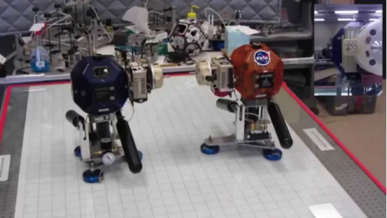
1-2 Two SPHERES satellites on the ground-test facility 1-g test environ-ment attempting to dock . . . 26
1-3 Two SPHERES satellites on the ISS facility 0-g test environment at-tempting to dock . . . 26
1-4 Docking port photographs . . . 27
2-1 Target vehicle capability and cooperation level . . . 30
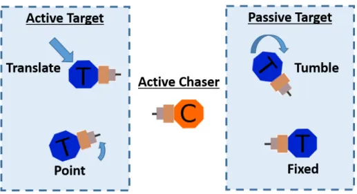
2-2 Active or passive target modes, where sensing or information transfer, and actuators are required for active translation and pointing . . . . 31
2-3 System theoretic risk assessment . . . 34
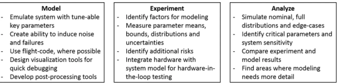
2-4 Modeling, experimentation and analysis aspects of a verification and validation framework . . . 36
2-5 Soft-Docking system model . . . 38
3-1 SPHERES master simulation . . . 48
3-2 Block diagram of docking port emulator for imitating function . . . . 50
3-3 Simulink schematic for docking port emulator . . . 51
3-4 Satellite vizualization for docking . . . 52
3-5 Visualization for docking port alignment . . . 52
3-6 Simulation Framework Information Flow . . . 54
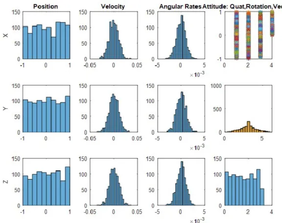
3-7 Inputs of graphic user interface for input variable selection and distri-bution . . . 55
3-8 Plots generated by graphic user interface showing distributions . . . . 56 3-9 Example of post-process variable-sensitivity graph . . . 59 4-1 Hardware testing and simulation in 1-g and 0-g . . . 64 4-2 Still frame of video plotting of docking port UKF state data (column 1:
position, velocity, quaternion, angular rates) and raw data (column 2: position (transformed to center of mass), raw position (rel. to camera), transformed quaternion, and raw quaternion) . . . 67 4-3 Still frame of video plotting of docking port camera imagery,
synchro-nized with plots in Figure 4-2 . . . 67 4-4 Locations of camera magnets . . . 68 4-5 Experiment and modeled data supporting essential keepout zone >
6mm (or 4.5mm from the surface) for one magnet . . . 69 4-6 Yellow "pinch-point" warning label on the left interferes with image
processing algorithm . . . 71 4-7 Target SPHERES bias-corrected raw IMU accelerations before collision
during Test 4 . . . 72 4-8 Chaser SPHERES bias-corrected raw IMU accelerations before
colli-sion during Test 6a . . . 73 4-9 Chaser position vs. time for simulated ‘truth,’ simulated ‘actual,’ ISS
state estimate, and ISS commanded state . . . 74 4-10 Chaser attitude quaternion for simulated truth, and ’actual,’ state
es-timate of quaternion on ISS, and commanded quaternion during ISS test . . . 75 4-11 The estimator-computed distance between satellites diverges to an
im-possible 3.5 meters, even though the SPHERES satellites are rigidly docked throughout the test . . . 77 4-12 Success histogram for varying SPHERES initial separation distance
before GN&C code modifications with only a 56% pass rate for a wide distribution of starting positions . . . 80
4-13 Histogram from uniform distribution of initial angular rates around Z-axis (tank-axis) showing docking success . . . 81 4-14 Minimum lance/mag separation distance for runs . . . 83 4-15 Histogram showing pass/fails for an N-sample run with various
drop-percentages for metrology without any camera data . . . 84 4-16 Histogram showing pass/fails for an N-sample run with increasing noise
level on metrology data . . . 85 4-17 Histogram showing pass/fails for an N-sample run with various noise
levels for relative state estimate of angular rates . . . 86 4-18 Histogram showing pass/fails for an N-sample run varying thruster force 87 5-1 Decision tree for deciding type of controller . . . 97 5-2 Adaptive model diagram . . . 100 5-3 PID controller response to a step attitude input command for the
docked configuration, when gains are tuned for single vehicle. . . 103 5-4 Attitude control response to reference step input, showing attitude,
rates, actuator commands, gains and error for the adaptive PID con-troller. . . 103 5-5 Undocked PID controller attitude response . . . 104 5-6 Adaptive controller attitude quaternion and reference command
through-out docking scenario. Just after time 110s, the SPHERES dock. At 180s there is a position step command, and at 245s there is an attitude step command. Remember the negative of a quaternion is the same transform, thus q2 is approaching the reference q2 correctly. . . 105 5-7 Hardware setup, with two SPHERES, each with a docking port pointed
towards the other, mounted in air-carriages on the low-friction table . 106 B-1 Test 6d chaser position, actual and commanded on ISS, and simulated
using ISS initial conditions . . . 121 B-2 Test 6d chaser quaternion, actual and commanded on ISS, and
B-3 Clean Beacon Data . . . 123 B-4 Noisy Beacon Data . . . 124
List of Tables
2.1 Rendezvous and docking sequence . . . 32
2.2 Consequence level of failures . . . 36
2.3 Systems theoretic risk chart for SPHERES satellite Soft-Docking . . . 43
3.1 Monte Carlo input variables . . . 57
3.2 Post processing scripts . . . 60
4.1 Ground testing . . . 66
4.2 Stochastic simulation testing for risk assessment . . . 79
5.1 Reference command combinations . . . 95
List of Acronyms
0-g Micro-gravity 1-g Gravity on Earth
3DoF Three degree of freedom 6DoF Six degree of freedom CAD Computer-Aided Design
DARPA Defense Advanced Research Projects Agency
DART Demonstration of Autonomous Rendezvous Technology EKF Extended Kalman Filter
FMEA Failure Modes Effects Analysis
FMECA Failure Modes Effects and Criticality Analysis GN&C Guidance, Navigation and Control
GPS Global Positioning System HW Hardware
IC Initial Condition
IMU Inertial Measurement Unit ISS International Space Station
MIT Massachusetts Institute of Technology MRAC Model Reference Adaptive Controller MRP Modified Rodriguez Parameter
NASA National Air and Space Administration PD Proportional Derivative
PID Proportional Integral Derivative
SPHERES Synchronized Position Hold Engage Re-orient Experimental Satellites STAMP Systems Theoretic Accident Modeling and Processes
STPA STAMP-based Process Analysis UDP Universal Docking Port
UKF Unscented Kalman Filter USAF US Air Force
Chapter 1
Introduction
Space mission designs are becoming increasingly complex as advancing technologies make exciting new operational concepts possible. Autonomous soft-docking, is of particular interest because it enables spacecraft reconfiguration, servicing, and debris capture. Such complex missions require a robust verification and validation framework to reduce risks. Many risk-reduction methods currently exist, but applying them in an integrated fashion to autonomous soft-docking under uncertainty to develop a verification and validation framework will help identify obstacles and assist in design of future missions.
1.1 Motivation
Today, there are over four thousand active spacecraft in flight [1]. There are over ten thousand pieces of debris orbiting the Earth, large enough for tracking [1]. In or-der to reduce the unnecessarily premature degradation of active spacecraft into space debris, autonomous spacecraft servicing has been suggested as a means of fixing satel-lites without the expense and high risk of manned missions. Another approach, of course, would be to clean up the debris. This might also involve docking in some manner, and, given the high volume of debris, autonomy may be useful. Another evolving mission concept is that of spacecraft assembly and reconfiguration. Imagine the potential of constructing a large space telescope from smaller satellites.
Vari-ous universities including Cornell, UT-Austin and Texas A&M have teamed up with NASA to demonstrate docking technologies with cubesats on programs such as On-Orbit Autonomous Assembly from Nanosatellites (OAAN) and Low Earth On-Orbiting Navigation Experiment for Spacecraft Testing Autonomous Rendezvous and Docking (LONESTAR) [12], [39].
While autonomous spacecraft soft-docking has been identified as a key enabler for these new mission types, it has proven challenging. In 2005 NASA’s Demonstration of Autonomous Rendezvous Technology (DART) mission resulted in premature ter-mination after a collision during approach [6]. The publicly released overview of the mishap report states that "inadequate systems engineering (including a lack of imple-mentation of software requirements, configuration control, validation of math models and testing) was a significant causal factor in the mishap." The report continues on to say "the [Mishap Investigation Board] determined that analyses to identify possible hardware/software faults failed to consider a sufficient set of conditions that could lead to the mishap. For example, the analyses focused on the effects of a complete loss of functionality of the navigation system’s components, but did not address the impact of a degraded functionality of those same components" [6]. Even successful rendezvous and docking missions like Orbital Express have had their issues, as a "se-quence of navigation and sensor problems... occurred during one of [Orbital Express’] unmated operations" instigating a thorough review [14]. Learning from these mis-takes and forging ahead with new developments would be critical for success of future missions.
Back in 2012, NASA published a road map detailing technological development priorities for the coming years. In that report, docking and capture (TA04 4.6.3), as well as on-board autonomous navigation and maneuvering systems (TA05 5.4.3) were among the high-priority research areas outlined [17]. Since then, NASA’s up-dated 2015 road map stresses the need to "develop the capability for highly reliable, autonomous rendezvous, proximity operations, and capture/attachment to (coopera-tive and non-coopera(coopera-tive) free-flying space objects" [38]. Additionally, according to Pavone and authors in their 2014 study on spacecraft autonomy challenges, a
"criti-cal step [for autonomous relative guidance] is establishing a rigorous process for their verification and validation (desirably with flight testing)" [40]. Post-flight analysis of an anomaly on Orbital Express revealed that "pre-flight testing did not reveal the sensor and navigation issues that occurred in flight" since it was deemed "infeasible for the spacecraft sensor suite and navigation software to be tested in a fully inte-grated, hardware-in-the-loop fashion" [14]. Restrictions on time and budget often limit the rigorousness of verification and validation (V&V) testing.
Given uncertain dynamic properties, the problem of autonomous rendezvous and docking becomes even more difficult for development and V&V. To begin, space-craft generally require attitude control for accurate pointing to accomplish a number of mission requirements. Traditionally, simple proportional-integral-derivative (PID) controllers (or even just PD controllers) are used since they have proven success-ful on flight programs [37]. Despite the non-linear dynamics of attitude control, these controllers demonstrate excellent performance for simple applications where the spacecraft physical parameters are known in advance so appropriate gains can be computed on the ground. However, in cases where parameter information is not known in advance, parameters change slowly, flexible structures are involved, space-craft reconfigurations occur, or in the presence of other un-modeled disturbances, these controllers may benefit from modification. A variety of control approaches ex-ist for coping with these uncertainties, ranging from gain scheduling to sliding mode control, each with pros and cons [19]. Among these methods, adaptation proves promising since it can be integrated with other types of control [19], mathematically proven as Lyapunov stable [25], designed for robustness to small disturbances and model uncertainties [22], and still achieve performance objectives [25], [22].
Current research on using adaptation for spacecraft attitude control shows theo-retic potential via mathematical proof of stability and simulation [46], [43], [9], [8]. Additionally, considerations such as stability under disturbances and actuator sat-uration limits have been studied with success [34], [28]. Adaptation has even been studied as a method for position control in robotic space systems [33].
space flight vehicles, however, due to the complexity of applications that would benefit from such a controller. Additionally, adaptation has perceived risk and complexity. Advancements in the validation process for adaptive algorithms are needed before they can be safely implemented on critical systems [27]. Flying a prototype with an adaptive algorithm for attitude control would provide insight as to potential risks and benefits of utilizing such methods on space programs for tasks related to jointed maneuver.
The goal of this thesis is to address the aforementioned motivations and research gaps in the confluence of improving verification and validation processes using flight testing of high-risk control algorithms aimed at rendezvous, docking and post-dock maneuvers for complex missions with uncertain dynamics. This includes creating and applying a V&V framework to a soft-dock application with uncertainty as well as developing a simple adaptive algorithm to validate performance in hardware and eventually in orbit for the particular application of controlling docked systems.
1.2 Autonomous Soft-Docking Background
Given the host of new mission possibilities for spacecraft servicing, reconfiguration, assembly, and debris capture, as well as the benefits of autonomy like reduced ground-dependence, research and development in autonomous docking is well warranted. Rea-sons for such focus on autonomy include potential benefits of increased safety during proximity operations, and when communication restrictions or delays are involved [36]. Additional motivation stems from the cost savings of autonomous servicing, rather than manned servicing [20]. With all these benefits, it is not a surprise that autonomous docking is not new.
In fact, autonomous soft-docking has been an evolving field in the space arena for decades. A NASA Goddard Space Flight Center report on satellite servicing from 2010 outlined a history of missions relevant to autonomous spacecraft docking [11]. After the successful demonstration of docking aspects of approach and capture on En-gineering Test Satellite VII by NASDA (the National Space Development Agency of
Japan), other missions tested additional capabilities. In 2003 and then 2005 (the same year as the aforementioned DART incident) the US Air Force Research Laboratory launched XSS-10 and then XSS-11, successfully performed proximity operations with microsatellites. DARPA’s Orbital Express mission in 2007 showcased autonomous spacecraft docking and servicing between the ASTRO and NextSat satellites specifi-cally designed for this purpose. Currently, the Russian Progress MS vehicle is capable of autonomous rendezvous and docking with the ISS to deliver cargo, as Russian vehi-cles have incorporated autonomy for decades (with manual override options). Other ISS delivery strategies involve manual berthing using the ISS robotic arm. Most re-cently cubesats are entering the rendezvous (and eventually docking) field, with the LONESTAR program
Some of the missions previously mentioned involved cooperation and high-levels of certainty. One of the obstacles of spacecraft servicing, however, would be limited information about or control over the target vehicle. In an demonstration experiment run inside the ISS, a satellite successfully docked with velcro to a tumbling target [36]. Others, like Fezjic and Andrade for example, have further developed this research to focus on the control algorithms for such missions [16], [2]. Continued efforts will undoubtedly involve handling target uncertainty.
1.3 Adaptive Spacecraft Attitude Control
Control after docking with an object remains challenging, since, for example, the spacecraft thrusters are no longer aligned in a known orientation relative to the center of mass, significantly changing the coupling between force and torque commands. Additionally, the inertia of the joint vehicle also changes. Docking contact dynamics are also difficult to model. Traditional controllers demonstrate limited performance in such circumstances, as conditions may deviate too far from nominal. Methods for sharing information between vehicles and devising a composite control strategy have been explored [24], however in the semi-cooperative case where information sharing is limited, these methods cannot be used. Other alternatives, such as gain scheduling
or controller swapping also have drawbacks when it is unclear how, or when, to modify controllers. Augmenting controllers with adaptive features which can handle parameter changes and nonlinear dynamics may allow them to perform even after docking with a little-known object.
Currently, adaptive controllers have little heritage in space, despite having flown successfully on aircraft [28]. While adaptive controls have been around since the 1950’s, robust, stable adaptive systems were only formally developed by the 1980’s [4]. Since interest has grown in space robotics missions, research on adaptation for space applications has become more prevalent in the last two decades.
In their paper on adaptive systems, authors Black, Haghi and Ariyur summarize the history, basic theory, implementation, and current development efforts [4]. They describe how state of the art adaptive controllers can be designed using Lyapunov’s method for stability. For robustness, there are various methods to handle disturbances and avoid adaptation runaway. Inputs with sufficient richness (persistent excitation) also help to ensure fast convergence. Beyond these design tools, various adaptive types exist as well. First, there are adaptive controllers and adaptive observers. Within the control regime, control can be indirect or direct, depending on whether or not the unknown parameters must be exactly identified, or the system simply controlled, respectively. Then, there is an assortment of control types to choose from, like model reference adaptive control (MRAC), adaptive sliding mode control, adaptive PID control, adaptive pole-placement, adaptive sliding mode control, and neural networks to name a few.
In the non-adaptive realm, robustness to large parameter changes or un-modeled dynamics means either designing a controller which can handle a wide range of envi-ronments (which is by definition inefficient for most cases), or swapping controllers. For instance, a PID without adaptation will have poor performance in regions far from where it was tuned, but with gain scheduling that region would grow. Knowl-edge of when to switch gains and to what value, however, is critical and potentially risky. Another control type, sliding mode control, handles parameter uncertainty well and is very robust. However, given its discrete nature, it is prone to chatter.
Certain limitations exist for adaptation as well. A persistently exciting input is required for parameter convergence to the actual value. In some cases, persistent excitation is needed simply for convergence at all, and rate of convergence is not guaranteed. Also, if the input is not persistently exciting, care must be given to stop adaptation runaway by implementing dead-zones or bounds for example. Finally, while adaptation may find a more efficient solution, there is a cost (fuel for example) to searching.
One of the greatest concerns for space applications, however, is risk itself, which must be mitigated through validation and test. Simulation and ground testing can only go so far, since dynamics are different in free-fall. Since adaptive attitude control has potential to benefit various space applications, there is value in putting research into validation and test to pave the way for testing in a relevant environment.
1.4 Verification and Validation
Numerous approaches to V&V have been studied across various disciplines. For space-craft, NASA’s Systems Engineering Handbook provides guidelines for everything from risk reduction to hardware-in-the-loop testing. The purpose of such oversight is to verify that what was designed meets the specifications, and validate that the sys-tem behaves as intended. Continuous risk assessment, cycling through identification, analysis, planning, tracking and control, serves to monitor and reduce risks as they arise from the design phase through validation [35]. Additional methods, which have been used in other applications besides autonomous docking, include systems the-oretic accident modeling and processes (STAMP) and failure-model effects analysis (FMEA) for risk management [29], [7]. Beyond these methods, in order to reduce the uncertainty that contributes to risk, research has gone into handling uncertainty and designing experiments to effectively reduce uncertainty [48], [47].
Despite progress, challenges still exist in the areas of verification and validation that reduce risks specifically for spacecraft docking [40]. While a high level approach to automated rendezvous and docking is thoroughly described in Fehse’s book, from
dynamics equations and control algorithms to V&V, implementation of such an ap-proach remains difficult due to intricacies in implementation [15]. To overcome these difficulties, several hardware-in-the-loop ground-test setups designed to replicate the complexities of docking have been developed for research, such as one at the Space-craft Robotics Laboratory of the Naval Postgraduate School [41]. Another test system at the Space Systems Laboratory at MIT (described in more detail in the next sec-tion), not only allows 3- degree of freedom (3DoF) soft-dock testing on the ground, but also in space [32], [45].
A contribution to the field by this thesis is reducing risk by developing and test-ing an integrated V&V framework by combintest-ing many of these studied methods for autonomous soft-docking under uncertainty. Further applying these methods in orbit allows improvement and validation of the process.
1.5 SPHERES Experiment Background
System validation implies ensuring the system meets intended goals in a relevant envi-ronment. Therefore, hardware testing in space would help with algorithm validation. A facility designed for this purpose by the MIT Space Systems Laboratory called SPHERES, for Synchronized Position Hold Engage Reorient Experimental Satellites, has been operating on the International Space Station since 2006 [42]. The facility consists of ground-testing laboratories (see Figure 1-2) and the ISS test setup (Fig-ure 1-3), including three small satellites and supporting equipment. The SPHERES satellites aboard the ISS have sensors, actuators, and on-board computing capability for navigating in the 6 degrees of freedom of space (shown in Figure 1-1).
Figure 1-1: SPHERES satellite, showing locations of thrusters, sensors, and docking port
A current SPHERES project aims to reduce the risk of autonomous docking in space by designing and testing control systems on a test platform inside the ISS micro-gravity environment [46], [32], [36]. In the summer of 2015, SPHERES docking ports arrived on the ISS for testing. A hardware checkout test was performed at the end of September 2015 that demonstrated functionality of the docking port mechanism. An additional docking test was conducted in March of 2016.
As SPHERES satellites move around, they consume fuel and thus their mass decreases. Additionally, once docked, the inertia matrix changes drastically. Finally, sensing and docking components (such as cameras, docking ports, and in the future, a robotic arm) may be added to the satellites that also change the mass, location of the center of mass, and inertia of the vehicle.
Each SPHERES satellite comes equipped with a suite of sensors (including a three-axis inertial measurement unit and ultra-sound receivers) that provide accel-erations, angular rates, inertial position, and the inertial to body frame attitude transformation. Sensor and model confidence information goes through a Kalman filter to create a state estimate. The state estimate (position, velocity, inertial atti-tude, and angular rates) is fed back to the controller, which commands the pressur-ized gas thrusters that maneuver the vehicle. There are no reaction wheels aboard, thus thrusters are responsible for attitude control as well. The controller operates given a reference command program running on-board the satellites. For testing, a detailed MATLAB/Simulink/C-code simulation exists which integrates the actual C-code that runs on the SPHERES with a MATLAB/Simulink dynamics simula-tor. This high-fidelity simulation includes sensor and actuator noise models, detailed physical parameters, timing delays, and environment non-linear dynamics.
Figure 1-2: Two SPHERES satellites on the ground-test facility 1-g test environment attempting to dock
Figure 1-3: Two SPHERES satellites on the ISS facility 0-g test environment at-tempting to dock
The docking port subsystem is comprised of an additional avionics box which interfaces with the SPHERES core computer, as well as the docking port itself. The avionics is responsible for computing the relative state between the satellite and any target vehicle in the field of view of the docking port camera. It uses a Kalman filter to process the incoming data, and then transforms it into the vehicle coordinate frame. The port itself consists of a camera on one side, and fiducial markings on the other (such that if two satellites were aligned for docking the camera would stare directly at the markings on the opposing satellite). When the markings are in clear, focused view of the camera for the tracking algorithm to locate the markings, the vehicle is said to have ‘target-lock.’ Once sufficient, consistent data has been collected after target-lock, that meets certain estimation criteria, the Kalman filter produces a state result which is sent to the controller. The docking port hardware also has a lance and
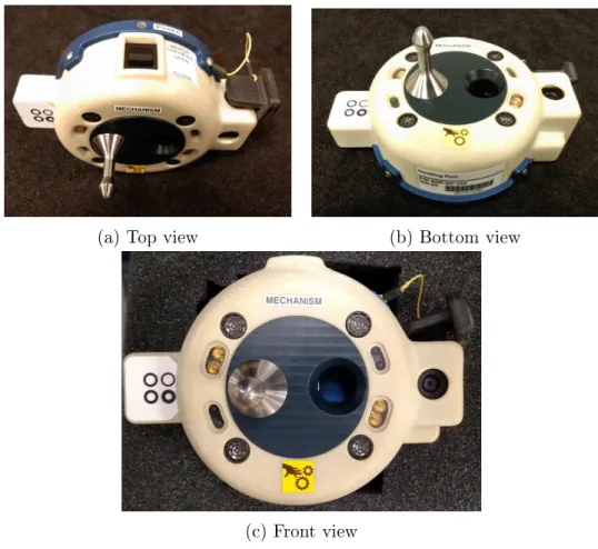
(a) Top view (b) Bottom view
(c) Front view
Figure 1-4: Docking port photographs
hole with a photo-sensor-triggered locking mechanism, such that there is only one correct orientation for docking. Figure 1-4 shows photographs of the docking port from different angles. In the photographs, one can see the lance and hole, the four round ultrasound sensors (symmetric around the front face), the fiducial markings (right) and the camera lens (left). Figure 1-4a gives a clear view of the manual dock button and the lens cover attached to a yellow string.
Using these experimental satellites with docking ports, developers can acquire experimental data to validate control algorithms and processes.
1.6 Thesis Objective and Roadmap
The objective of this thesis is to figure out areas of concern for soft-docking missions, develop a systematic approach to identifying them and reducing risk, create tools
for such methods, test out tools in a relevant environment, use methods to assess feasibility of adaptive methods for joint maneuvers and work on validation of ap-plying adaptive controls in orbit. The goal is to enable future on-orbit soft-docking missions through improved verification and validation processes using simulation and experiment.
Chapter 1 introduces the topic of autonomous soft-docking, and its importance Chapter 2 develops approach to risk assessment and V&V for docking applications Chapter 3 describes implementation of modeling for V&V
Chapter 4 describes simulation, testing, and results
Chapter 5 describes an adaptive attitude-control case study for jointed maneuver Chapter 6 summarizes work, contributions, and describes potential extensions
In more detail, Chapter 1 has described how docking and post-dock control are of interest for robotic assembly and spacecraft servicing missions, among others, giving motivation for research into V&V [46], [32], [38]. Chapter 2 follows with develop-ment of a risk reduction framework specifically for soft-docking using an integrated approach. In Chapter 3, the development process of building the models and tools for that approach is described. The approach is applied to SPHERES docking to demonstrate software and hardware implementation. Next, in Chapter 4 the results found by cycling back and forth between 3 DoF ground testing, pure simulation, and ISS testing, explain the lessons which contributed to improvements. Chapter 5 describes the design and implementation of an adaptive attitude-control method for using on-board docked SPHERES satellites in the future as a test-case to assess how well such algorithms might work for docking applications, as well as to develop an approach toward validating such algorithms in space. Finally, Chapter 6 ends by synthesizing lessons learned, summarizing contributions, and motivating future work in soft-docking V&V.
Chapter 2
Verification and Validation
Framework Design for Soft-Docking
Numerous independent risk reduction techniques exist which could apply to controller development for soft-docking. These include both failure-based and systems-based approaches, as well as experimental design for key parameter identification. Here, the design process for developing an integrated risk-reduction framework for control-system testing is examined.
Existing methods are introduced in the context of soft-docking, an integrated method is described, and then applied to SPHERES satellites for soft-docking. The methods here serve as structure for the testing and analysis in this thesis.
Before delving into risk reduction, it is helpful to define the application itself to discern the types of requirements that must be met.
2.1 Soft-Docking
Soft-docking (as opposed to colliding) may happen when the relative velocity and angular rates between two vehicles are low enough to allow a mechanical connection to join them without any structural damage. A similar concept, termed ‘berthing,’ means that the vehicles get close together, and another maneuverable device (such as a robotic arm) positions the vehicles for the final link [15]. In order to reach a
stage where this can happen, the chaser vehicle must gain enough information about the target to approach, either through its own sensors, or from communication with the target. Therefore, the target spacecraft’s cooperativeness and technical capability levies requirements on the chaser for soft docking.
2.1.1 Cooperativeness in Soft-Docking
Much study and research has gone into cooperativeness in soft-docking, as evidenced from discussions in Nolet’s thesis [36]. The level of spacecraft cooperativeness and capability maps out a space of evasive, passive and collaborative target-chaser ma-neuvers, as shown below in Figure 2-1. It is assumed the chaser is fully capable.
Figure 2-1: Target vehicle capability and cooperation level
Three key aspects of capability are the ability to sense, actuate, and communicate. Sensors and filtering on-board the target vehicle can provide information about the vehicle state (attitude, angular rates, position and velocity), in relative (to the chaser), local, or absolute terms. If the target vehicle has fuel and a working actuation system, it may translate, rotate or both to assist with soft docking. Finally, the target vehicle may transfer information about its state to the chaser, receive state information about the chaser, and even respond to commands from the chaser. When both the chaser and the target spacecraft have all three capabilities, they may be fully collaborative. For example, if the target communicates all sensed state information with the chaser vehicle and additionally has full attitude and position control, it is said to be fully collaborative and cooperative (far right column). Even limited target-sensing may be collaborative, as the target may help in pointing towards the chaser using its actuators. A piece of space debris with no fuel, sensing information, or ability to
communicate would be classified as passive and uncooperative. Finally, evasive vehi-cles would use their sensing capabilities and actuators to actively avoid docking. For soft-docking, this thesis examines both collaborative and passive regimes, neglecting evasive maneuvers.
Target Motion
For the target to collaboratively point towards the chaser, it requires relative state information. The information may be obtained from the chaser, or by filtering data from the sensors (like an inertial measurement unit or vision system) on-board the target. Additionally, the target would require a functional actuation system, like re-action wheels or thrusters for attitude control. Without working actuators or relative state information, the target may be considered passive, maintaining a fixed orienta-tion and posiorienta-tion, or tumbling. Both active and passive target moorienta-tions are shown in Figure 2-2.
Figure 2-2: Active or passive target modes, where sensing or information transfer, and actuators are required for active translation and pointing
2.1.2 Chaser Control Objectives for Soft-Docking
Successful autonomous soft-docking can be broken into the far-field approach, near-field sensing and motion, docking, and finally post-dock operations [15, p. 9]. Each
phase has success criteria as well as control-related objectives, depending whether the approach is cooperative or not, outlined in Table 2.1.
Table 2.1: Rendezvous and docking sequence
Stage Description Cooperative
Objectives UncooperativeObjectives Far-Field Approach close
enough to enable near-field sensors
Approach using information from ground and the target about target location
Approach using information from ground only Near-Field Sufficient knowledge of relative state to position vehicle for docking
Approach using chaser and target sensors for relative state knowledge
Approach using chaser on-board sensors only
Docking Successful capture
by mechanism Dock using chaserand target mechanism Chaser docks totarget Post-Dock Stable position and
attitude joint control
Chaser and target coordinate actuation commands
Chaser handles all actuation
Turning these objectives into requirements, by adding metrics and tests, helps converge on a design. Ensuring that these requirements are met is the process of verification.
2.2 Risk Reduction Approaches
Once some requirements have been outlined for soft-docking, an approach for algo-rithm development and technical-risk reduction can be developed. Various risk man-agement techniques already exist, ranging from failure-based assessment (FMECA Failure Mode Effects and Criticality Analysis) to systems approaches (STAMP -Systems-Theoretic Accident Modeling and Processes) [7] [30]. Careful design of ex-periments and system modeling can reduce uncertainty on high-impact parameters (Sobol) and thus reduce risk [48][47].
2.2.1 Technical-Risk Management
The idea behind risk management and reduction is to identify hazards, likelihoods and consequences to create solutions that minimize harmful outcomes [35]. A simple risk management practice is to simply identify possible failures, and diagram them by estimating likelihood and consequence. Likelihood is given a value of 1-5, where 5 is extremely likely, and consequence a value of 1-5, where 4 is mission critical and 5 is detrimental even beyond the mission [35].
Once risks are brought to the attention of the team, measures to better quantify and reduce or eliminate risks can be taken. The process of identifying, quantifying, and reducing risks continues throughout the program.
While this high-level approach to technical-risk management brings risks to the foreground for discussion, more detailed risk analysis in combination with experimen-tation can help address the underlying causes.
For this thesis, a detailed risk reduction plan can be outlined as follows: ∙ Identification of influential variables that affect risk
∙ Determination of ranges and distributions of these variables ∙ Analysis of system sensitivity to identified variables
∙ Experimentation or redesign to reduce uncertainty or influence of critical vari-ables
Beyond developing mitigation processes, improving observation of problems early in design also reduces risk. All aspects from identification to mitigation, to tracking are considered for risk reduction.
2.2.2 Risk Assessment Strategies
Many risk assessment strategies exist across various fields and agencies. For creating a comprehensive approach for this thesis, two popular assessment types were studied, integrated, and applied to the soft-docking problem.
The first method, called Failure Mode Effects and Criticality Analysis, FMECA, is a risk assessment process outlined by the Department of Defense [7]. The process involves listing and tracking potential failures, determining their consequence, and providing a mitigation strategy. The addition of a criticality metric allows developers to compare importance of proper functioning of various components.
While FMECA provides a framework for tracking risks associated with particular failures, sometimes problems occur because failures went unnoticed or mitigation control strategies were not built into the system. Additionally, emergent failures may arise at the system level due to interactions between subsystems. Software ‘failures’ are particularly difficult to track, since software generally does exactly what it was programmed to do, and therefore does not fail. These aspects are not captured well using the FMECA approach.
A systems control theory approach to risk reduction, however, entails identifying risk factors, and ensuring that there are methods to observe, mitigate, and control them [29]. Figure 2-3 shows the cycle of risk mitigation using this approach.
Figure 2-3: System theoretic risk assessment
Much like control systems, the concepts of observability and controllability are applied to risk factors to ensure they are mitigated. If, for example, there is no way to know that spacecraft attitude pointing is poor, then there is no way to control this risk. However, if attitude data is captured, then poor pointing may be observed, and mitigation techniques applied. Leveson and team outline a process by which designers can apply this risk assessment technique to their own applications [30]. In Section 2.4.1 this process is applied to an example soft-docking mission using SPHERES satellites.
2.2.3 Modeling and Experimentation
Fueling any risk assessment is the system itself which is the source of all risk factors and potential failures. Developers must determine what the failures and risk factors are before any assessment is possible. Literature, historical evidence, experiment and modeling all provide insight as to where things might go awry. Another approach is to start with the requirements and think about what happens when these are not met.
Analysis may also come from simulation and test. Two typical approaches are ver-tex testing (checking bounds) and Monte Carlo (stochastic) testing [48]. Stochastic testing is easier in simulation than in hardware (given time constraints), thus infor-mation gained from simulation drives which hardware tests are selected. Chapters 3 and 4 demonstrate how the approach described in the remainder of this chapter of simulation and experiment may be used for reducing risk in soft-dock applications.
2.3 Verification and Validation Framework Design
Verification and validation (V&V) refer to the process of ensuring the design meets requirements, and also that it acts as intended in a relevant environment [35]. Since spacecraft docking occurs in a free-fall environment, there are particular barriers to testing in a relevant environment. Simulation of the environment then plays a greater role in system validation. Fehse explains the basics of verification and validation pro-cess for automated spacecraft rendezvous and docking in Chapter 10 of his book [15]. The key elements are the development of a detailed system model and assessment tools for checking performance and identifying risks. Experimentation helps in en-suring the accuracy of the model. Finally, assessment of resulting runs provides more information for further investigation. These three areas which correspond to sections in this chapter and contribute to development of a sound verification and validation framework are outlined in Table 2.3.
Figure 2-4: Modeling, experimentation and analysis aspects of a verification and validation framework
Spanning this entire framework is risk management. As information is gained about the system through such experiment and simulation, risks can be estimated for tracking and mitigation purposes. For the case of soft-docking, some risks and associated consequence levels are outlined in Table 2.2 below:
Table 2.2: Consequence level of failures
1 2 3 4 5
Data storage failure Communication failure Miss Collision Sensor failure Empty fuel tank
Actuator failure Docking mechanism failure
A systems-level risk management approach begins with brainstorming potential risk factors, and how they might be identified and mitigated. For autonomous soft-docking, some factors which were compiled from experience, and various resources, are listed below. [15],[26],[36].
General Risk Factors and Contributors: ∙ Missing data (no saved data)
∙ Bad/missing sensor info
∙ Timing delays (delayed sensor info) ∙ Unmodeled disturbances
∙ Avionics processing or interface issues
∙ Invalid models (bad assumptions)
∙ Incorrect parameters
∙ Actuator issues (control authority, timing, changing thrust)
∙ System changes in time
∙ System requirements change in time
∙ Test plan does not test objectives, or obscures results
∙ Test plan not implemented correctly
∙ Limitations on duration/complexity/number/types of tests
∙ Emergent problems with communication system, propulsion system and power system
The remainder of this section shows how modeling, diagnostic tools and experi-mentation can identify and mitigate such risks. Section 2.4.1 includes a walk-through of how to systematically go through factors to reduce risk.
2.3.1 System Modeling
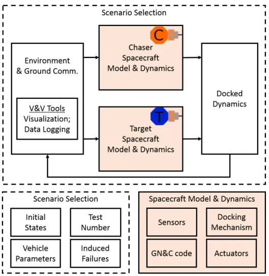
For in depth V&V, modeling helps test the system and to identify and quantify risks and risk factors. A general schematic for modeling soft-docking is shown below in Figure 2-5. It includes both the models of the vehicles themselves, as well as the environment and supporting diagnostic tools which go with them.
Figure 2-5: Soft-Docking system model
Additionally, when developing the model it is important to build in the capability to arbitrarily ‘break’ components and introduce noise to sensors and actuators. While during initial design phases these may be ignored, as the design progresses one can en-sure robustness by adding disturbances to the system and checking response. Section 3.1 describes generic modeling in more detail, while Section 3.2 shows a real-system application using the SPHERES facility.
2.3.2 Model Diagnostics
An equally important aspect of the model, beyond matching the physical attributes of the system, is the diagnostic portion. Development goes faster if problems are easy to spot. Spending time creating visualization tools and data processing tools which
will make problems obvious will reduce risks over the course of the design process. These diagnostics should aid in observing risk factors.
Below is a list of various diagnostic tools that will assist in development and test: ∙ Visualization Tools
– Vehicle position and orientation – Docking alignment and error ∙ Data Logging & Post Processing
– Time
– Chaser and target state vectors (position, velocity, attitude, angular rates) – Control commands
– Control error – Fuel consumption
– Dock state and mechanism state
– Vehicle separation and relative orientation
2.3.3 System Characterization through Experiment
Models are only as accurate as the parameters which go into them, thus experiments provide the parameters necessary for simulation. Below is a list of experiments which may be useful to gain information about the system:
∙ System Characterization – Mass identification – Inertia identification – Volume identification ∙ Actuator Characterization
– Timing
– Thrust profile(s)
– Thruster pointing directions – Multiple thruster effects – Torque-device response profile – Fuel capacity
∙ Sensor Characterization – Sensor hand-off timing – Sensor(s) noise and bounds – Sensor output frequency
∙ Docking Mechanism Characterization – Timing
– Acceptable contact forces
– Acceptable position and angle offsets
Care must be taken to not only identify the mean values for various parameters, but also the distribution, uncertainty, and bounds on various values. Information gained will make the simulation more accurate, and allow simulated testing of the operational space.
2.3.4 Model Scenario Selection
Once basic system characterization is achieved through experimentation and reflected in the model, numerous simulations and experiments may be run to reduce risk. Simulations will guide where problems might occur, and where more experimentation is needed. A thorough description of using stochastic simulation to reduce risk may be found in Chapter 3.3.
Developers must balance resources, risk, and value when designing experiments. As a thought exercise, questions for experiment design are listed below:
Experiment Design Questions ∙ What tests are necessary?
∙ How should tests be sequenced (or parallelized)? ∙ How invasive or risky are tests?
∙ How much would the results impact the design? ∙ Is the test ‘exploratory’ or ‘acceptance?’
∙ How effective or complete is the test?
∙ Does the test need to happen just once, or whenever there is a change?
∙ What resources (time, money, personnel, equipment, etc.) are needed for the test?
Next, the key variables and parameters must be determined to map out the trade-space of potential experiments.
2.4 Example: SPHERES Docking
In order to illustrate the risk reduction process for spacecraft soft docking, the SPHERES facility was used (refer to Section 1.5 for background). A SPHERES project aimed at docking SPHERES satellites equipped with docking ports applied some of the processes described earlier in this chapter to reduce risk. An introduction to the risk assessment process is outlined here, while Chapter 3 and Chapter 4 offer more detail on the modeling, testing and results.
2.4.1 Risk Assessment
For SPHERES satellite docking, risks range from high level risks (danger to astro-nauts) to experiment-level risks (colliding during a docking attempt). For the purpose of this research, only experiment-level risks were considered, as the SPHERES facil-ity has long been tested for safety. Additionally, component failures are considered beyond the scope of this analysis, as they also reflect a problem with the experiment facility and not the rendezvous and dock algorithms.
One benefit of the SPHERES facility is the ability to perform a whole range of uncooperative and cooperative missions. Satellites may work independently or communicate information. This allows developers to fully control the cooperativeness of the test.
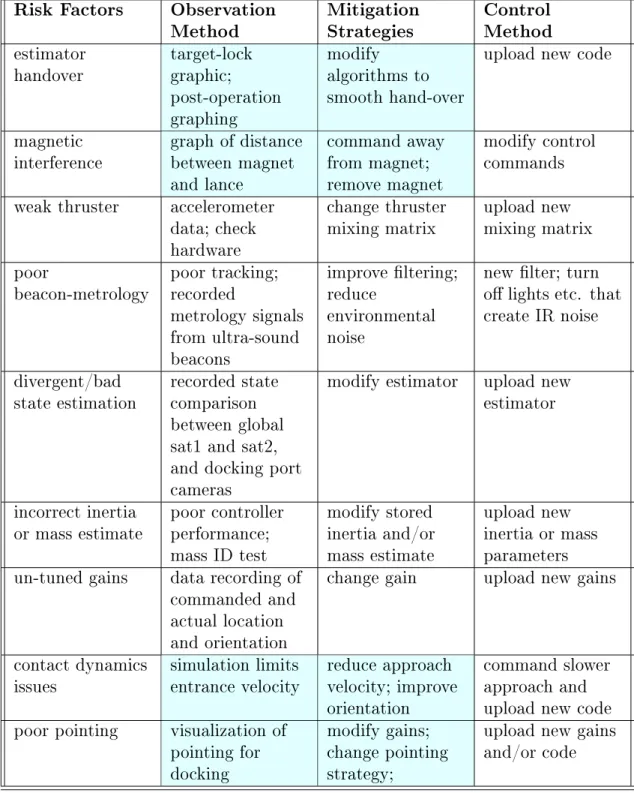
In Section 2.2.2, the concept of systems theoretic risk analysis was introduced. Here, it is applied to a satellite docking application. Risk factors were determined, along with methods of observation, mitigation strategies, and control methods. For example, poor pointing was identified as a risk which could lead to failure to dock. Potential contributors to poor pointing range from poor sensing, inadequate control authority, to coding errors. To determine if pointing is poor however, there must be diagnostics in place which allow observation of this problem. Therefore visualization and graphing tools must be created that clearly demonstrate the pointing accuracy of the chaser and target vehicles. Next, if the pointing is shown to be inadequate through these diagnostic tools, mitigation approaches must be developed. One might be changing the pointing algorithm. Finally, there must be a way of implementing the changes, like uploading new code. Such cycles were thought out for a variety of factors as shown in Table 2.3.
Cycling through these steps reduces risk. Sometimes, steps are missing, and this is when the approach is most helpful. The tools and strategies in the highlighted cells in Table 2.3 were only developed as a result of gaps in this chart. For example, mitigation strategies for magnetic interference had to be thought up once it was realized there might be a problem through experimentation. Observation tools were also missing
Table 2.3: Systems theoretic risk chart for SPHERES satellite Soft-Docking Risk Factors Observation
Method MitigationStrategies ControlMethod estimator
handover target-lockgraphic; post-operation graphing
modify algorithms to smooth hand-over
upload new code
magnetic
interference graph of distancebetween magnet and lance command away from magnet; remove magnet modify control commands weak thruster accelerometer
data; check hardware
change thruster
mixing matrix upload newmixing matrix poor
beacon-metrology poor tracking;recorded metrology signals from ultra-sound beacons improve filtering; reduce environmental noise
new filter; turn off lights etc. that create IR noise
divergent/bad
state estimation recorded statecomparison between global sat1 and sat2, and docking port cameras
modify estimator upload new estimator
incorrect inertia
or mass estimate poor controllerperformance; mass ID test modify stored inertia and/or mass estimate upload new inertia or mass parameters un-tuned gains data recording of
commanded and actual location and orientation
change gain upload new gains
contact dynamics
issues simulation limitsentrance velocity reduce approachvelocity; improve orientation
command slower approach and upload new code poor pointing visualization of
pointing for docking
modify gains; change pointing strategy;
upload new gains and/or code
for easily identifying pointing problems, thus tools were developed. Another concern was how incorrect gains and inaccurate mass/inertia or thruster force information are
all coupled and it may be difficult to differentiate between them. Awareness of these weakness makes the need for tool development more obvious.
2.4.2 Verification and Validation Framework
A detailed framework for SPHERES satellite docking verification and validation is described in various sections throughout the thesis. The risk management strategy outlined in Table 2.3 serves as the foundation for later tool development and analysis. In Section 3.2 development of system models and visualization tools is discussed to allow for observation of issues. Then in Section 3.3 stochastic simulation methods are described to allow for risk assessment. Chapter 4 shows the implementation and results.
2.5 Summary
Approaches to developing a solid verification and validation framework specifically for soft-docking were described in this chapter, along with a hardware-based application example. The remainder of this thesis serves to apply both the techniques, and the identified risk factors and observation types outlined here to improve V&V for soft docking spacecraft. While all risks will not be discovered at the onset of mission design, iterating risk assessment, simulation and experiment will help in identifying and mitigating them as soon as possible.
Chapter 3
Development of Verification and
Validation Tools for Soft-Dock
Control Systems
In order to test a soft-dock controller, it is useful to develop a model that emulates the spacecraft in its environment. The simulation must determine the states of both the chaser and target by modeling the system dynamics, control algorithms, docking mechanism, sensors and actuators. Additionally, development of assessment tools allows one to measure and visualize performance. This chapter shows how a generic SPHERES satellite simulation was enhanced for docking, and further improved by incorporating the verification and validation framework from Chapter 2 to develop tools needed for V&V.
The process is explained as follows. First, using the framework design from the previous chapter, critical elements for simulation are described for a generic soft-dock system. Next, these elements were simulated for SPHERES docking. Augmenting the simulation, a method was created for stochastically selecting scenarios for running numerous cases. Finally, post-processing tools were developed for data assessment.
3.1 Generic System Model Development for
Soft-Docking
Back in Section 2.3.1, the concept of system modeling was introduced and motivated. Now the system component models may be developed. In Figure 2-5 several elements were shown, including the dynamics control loop model, the satellite emulator, sce-nario generation, and V&V tools. These aspects have been modeled in prior research and on flight programs, however an overview of the process in context of risk-reduction is shown here [15][16][36][35].
When beginning the system modeling process, a decision must be made as to the software package or programming language used for the model. An advantage to high-level programming (graphical languages for example) is the ease in which a non-programmer may understand the workings of the model. Code-generation may even remove some burdens of programming. On the other hand, graphical languages tend to require more disk space and overhead than simpler languages, which may be prohibitive on a flight system. Users also have less control over the details. Care should be taken to explain both how to use a model by carefully defining the inter-face, as well as how the model works with its inherent assumptions. In this manner engineers can easily return to the code to make modifications later if assumptions are found invalid, or higher fidelity is needed.
Once the software is chosen, the development process may begin. When developing a soft-dock model for controller testing, the basic dynamics constitute the core of the model. Appendix A.1 walks through some relevant equations and definitions for reference. Specific to docking, the model must have the capability to transition back and forth between the un-docked and docked cases, keeping in mind the change in location of the center of mass, as well as total mass and inertia. A decision regarding the fidelity of the modeling of contact dynamics must also be made, and would be dependent on the quality of available testing data and the acceptable risk levels for the mission.
station must also enter the model. State information in the form of GPS data, two-line element sets or ranging information from the ground on a contact schedule may be included in the model. Relevant celestial objects that influence certain sensors, like the Sun, Earth or Moon, might also be modeled.
For the spacecraft models, the objective is to emulate function, and "test like you fly" as much as possible. This means using the actual flight GN&C if possible in the model. To support the controller, sensor and actuator emulators which are vehicle-specific must be developed for the chaser, and in the case of a cooperative vehicle, the target as well. For the purpose of performance measurement, consumables (like fuel or power) may also be tracked as necessary for a mission. Additionally, the docking port mechanism must be emulated, along with any associated sensing or locking.
Throughout, careful attention to timing considerations and the accuracy of inter-faces should be considered. Information arriving at the wrong time is a big risk as it may be worse than no information at all. To test timing and function, verification tools should be created during the modeling process to check the validity of the sim-ulation. Backing the simulation with inputs from experiment and matching results also helps to validate the model.
After creating a system model that is backed by experimental data, and can be modified to emulate 0-g dynamics, one can create a wrapper to run the simulation numerous times while adjusting variables. This allows statistical testing for confidence building by identifying areas of risk. These types of tools may also serve to diagnose problems found in testing and operations.
3.2 SPHERES Docking Simulation
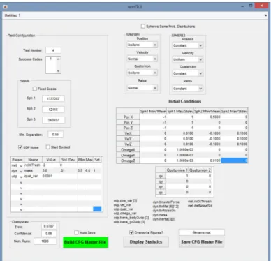
In order to support rapid flight-worthy algorithm development, a simulation for SPHERES was coded and validated through careful experimentation with hardware on the ground, and data from on-orbit testing [45]. The MATLAB Simulink-based SPHERES simulation allows multi-satellite scenario testing in both 3DoF and 6DoF, using flight code. The simulation allows users to modify SPHERES initial conditions,
add on payloads, and run numerous successive tests to evaluate performance and predict the behavior of the satellites.
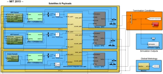
The simulation framework consists of initialization, visualization, and analysis tools, combined with an environment model containing models for three SPHERES satellites. These models include a dynamics model, a metrology beacon emulator, SPHERES flight code modules, and emulators for sensors, actuators, and any payload. Emulators need not operate the same way as in hardware, but must accurately reflect the interface, timing, noise, and disturbances the system may see in flight. Figure 3.2 shows the top-level Simulink block diagram of the simulation. From left to right, payload emulators (for the docking ports), satellite GN&C code, plant dynamics, and sensor models make up the core of the simulation. Termination, verification, and external beacon metrology emulation may be seen from top to bottom on the right side of the model.
Figure 3-1: SPHERES master simulation
The base model was developed and validated previously by a succession of SPHERES team members over a number of years [42][36][32][46]. Modifications were necessary to enable simulated SPHERES satellite docking, however, including changes to the dynamics propagator and the addition of docking port emulators. The capability to detect docking and enable ‘joint-dynamics’ mode was a team effort on the program [45].