Development of Integral Actuation Technology for Composite
Rotorcraft Structures
by
Mads C. Schmidt
B.S., Massachusetts Institute of Technology (1998)
Submitted to the Department of Mechanical Engineering
in partial fulfillment of the requirements for the degree of
Master of Science in Mechanical Engineering
at the
MASSACHUSETTS INSTITUTE OF TECHNOLOGY
BARKER
February 2001
MASSACHUSETTS INSTITUTEOF TECHNOLOGY
@
Massachusetts Institute of Technology 2001
All rights reserved
LIBRARIES
Signature of Author...
...
Department of Mechanical Engineering
27 November 2000
Certified by ...
...
Nesbitt Hagood IV
Associate Professor, Department of Aeronautics and Astronautics
Thesis Supervisor
C ertified by ...
...
(
JSeth
Lloyd
Assistant Professor, Department of Mechanical Engineering
Mechanical EnginesagAt%@Qty Reader
A ccepted by ...
MiTLibraries
Document Services
Room 14-0551 77 Massachusetts Avenue Cambridge, MA 02139 Ph: 617.253.2800 Email: [email protected] http://libraries.mit.edu/docsDISCLAIMER OF QUALITY
Due to the condition of the original material, there are unavoidable
flaws in this reproduction. We have made every effort possible to
provide you with the best copy available. If you are dissatisfied with
this product and find it unusable, please contact Document Services as
soon as possible.
Thank you.
Due to the quality of the original material there is some bleed
through.
Development of Integral Actuation Technology for Composite Rotorcraft
Structures
by
Mads C. Schmidt
Submitted to the Department of Mechanical Engineering on 27 November 2000, in partial fulfillment of the
requirements for the degree of
Master of Science in Mechanical Engineering
Abstract
Helicopters experience a large level of vibration in flight due to the unsteady aerodynamics associated with the spinning rotor. Reduction of vibration can improve ride comfort, reduce cabin noise, and improve maintainability and functional reliability. Blade mounted actuation technology using smart materials has made effective rotor vibration reduction possible.
The goal of the work presented in this thesis is to further develop integral actuation tech-nology for rotor blades. Active Fiber Composite (AFC) plies, consisting of piezoelectric fibers embedded in an epoxy matrix, are embedded in the skin of model scale rotor blades to allow the blades to be actively twisted to counteract vibratory aerodynamic loads.
The concept of using AFCs for integral rotor blade actuation was first demonstrated in 1998.
A first generation scaled blade was developed by MIT and Boeing Helicopters and was hover
tested. This blade experience several AFC actuator failures, either through loss of electrical connection or through internal short circuits. The blade also did not meet peak actuation expectations. This thesis advances the integral actuation technology to avoid the problems experienced in the first generation blade. Manufacturability improvements are made through redesign of blade components associated with the active material. These include the blade power bus, the AFC actuator pack leadouts, and the electrical connections to the AFCs. Material level work focuses on the mechanical and electrical behavior of embedded AFCs. It was shown that the mechanical behavior of the AFCs is non-linear and voltage dependent. The dielectric properties of the AFCs are studied and shown to be strongly voltage dependent.
A second generation integrally actuated blade is built in conjunction with Boeing
Heli-copters. Bench testing results of this blade are presented. The blade performed as expected, yielding a 2.3*/m twist rate through the span of the blade at 3000Vpp, OVDC drive voltage. Blade heating and current draw were observed to be significant, but in line with expectations based on testing of individual AFCs.
Thesis Supervisor: Nesbitt Hagood IV
Title: Associate Professor, Department of Aeronautics and Astronautics
Mechanical Engineering Faculty Reader: Seth Lloyd
Title: Assistant Professor, Department of Mechanical Engineering
Acknowledgements
It is with heartfelt gratitude that I dedicate this thesis to all those who have played a role in its successful completion. I would like to thank my family and my friends for their support and encouragement through the past two and a half years. Lots of hugs and kisses go to Amanda for sticking by my side through all the hard times - I promise I'll be happier from now on.
Funding for this research was provided by the Defense Advanced Research Projects Agency, under contract MDAA72-98-3-0001, and was monitored by Ephrahim Garcia of the DARPA Defense Sciences Office.
Contents
1 Introduction 19
1.1 Motivation . . . . 19
1.2 Active Fiber Composites . . . . 22
1.3 Objectives . . . 25
1.4 Approach . . . . 25
1.5 Summary of Document . . . . 26
2 State of Integral Actuation Technology 29 2.1 Overview of Blade Mounted Actuator Technologies . . . . 29
2.2 Integrally Actuated Blades . . . . 31
2.2.1 Actuator . . . . 31
2.2.2 Blade Scaling . . . 32
2.2.3 MIT/NASA Langley Integral Blade . . . 32
2.2.4 MIT/Boeing Integral Blade . . . 33
3 Active Fiber Composite Testing 41 3.1 Motivation . . . . 41
3.2 Approach . . . . 42
3.3 AFC Properties Review . . . . 43
3.4 Modeling Concept . . . . 43
3.5 Coupon Lamination Testing . . . . 46
3.5.1 Test Samples . . . . 46
3.5.2 Test Procedure . . . . 46
3.5.3 3.5.4 3.5.5 3.6 Blade 3.6.1 3.6.2 3.6.3 3.6.4 3.6.5 3.7 Blade 3.7.1 3.7.2 3.7.3 3.7.4 3.7.5 Lamination Procedure... Results . . . . Summary ...
Pack Lamination Testing .
Motivation . . . .
Test Procedure . . . . Results . . . . Analysis . . . . Summary . . . . Pack Heating and Current Draw Motivation . . . . Test Samples . . . . Test Procedure . . . . Heating Results and Analysis Current Draw Results...
Testing
3.7.6 Power Loss
3.7.7 3.7.8
Blade Current Requirements an Summary . . . . . . . . . . . . . . . . . . . . . . . . d Performance Envelope . . . . .
4 Design and Manufacturing of Internal High Voltage Connections
4.1 Motivation . . . .
4.2 Approach . . . .
4.3 Actuator Pack Leadout Design . . . . 4.4 Flexible Circuit Design . . . .
4.4.1 Motivation for Using a Flexible Circuit . . . .
4.4.2 Flexible Circuit Design . . . .
4.5 Blade Manufacturing Procedure . . . .
4.5.1 Blade Section 4.0 Overview . . . .
4.5.2 Spar Layup . . . .
4.5.3 Electrode Tab Protection . . . .
4.5.4 Spar Cure . . . . 8 48 50 50 52 52 52 54 54 57 57 57 58 58 60 61 63 74 75 77 77 78 79 81 81 82 83 83 85 86 86 . . . .
4.5.5 Fairing Assembly . . . . Blade Section 4.0 Manufacturing Results Actuation Testing Setup and Procedure Blade Section 4.0 Testing . . . . Summary . . . .
5 AMR Blade Design and Testing
5.1 AMR Design . . . .
5.1.1 Blade Geometry and Layup . . . .
5.1.2 Actuator Packs . . . . 5.1.3 Internal Flexible Circuit Details
5.1.4 External Circuit Design . . . .
5.1.5 Power Distribution Board... 5.1.6 Options in Case of Flexible Circuit
5.2 Manufacturing . . . .
5.3 Bench Testing of AMR Process Blade . .
5.3.1 Testing Setup . . . . 5.3.2 Actuation Testing Results... 5.3.3 Blade Mechanical Properties . . .
5.3.4 Blade Current Draw and Heating
5.3.5 Actuator Pack Failure History . 5.3.6 Destructive Testing . . . .
Failu
5.3.7 Windtunnel Testing Recommendations .
101 . . . 102 . . . 102 . . . 102 . . . 1 0 5 . . . 106 . . . 1 1 0 re . . . 110 . . . 111 . . . 1 1 2 . . . 1 1 6 . . . 1 1 7 . . . 1 2 1 . . . 124 . . . 129 . . . 132 . . . 134
6 Conclusions and Recommendations
6.1 Summary and Conclusions . . . .
6.2 Recommendations for Future Work . . . .
A Coupon Testing Data
B Blade Section 4.0 Supplement
9 4.6 4.7 4.8 4.9 . 89 . 94 94 98 . 99 137 137 139 149 153
C AMR Design and Testing Supplement 159
C.1 Blade Actuator Pack Data ... 159
C.2 Bending Stiffness . . .. . . . .... ... .. . . . ... . .. . 159
C.3 Blade Dynamics ... ... 159
C.4 Blade Crossectional Pictures ... 161
C.5 AM R Flexible Circuit ... 161
D Flexible Circuit Connectors 173 E Piezoelectric Ceramic Data 179 F Core Void Elimination 181 F.1 M otivation . . . 181
F.2 Hypotheses of void formation ... ... 182
F.3 Test procedure ... ... 183
F .4 R esults . . . 185
F .5 A nalysis . . . 186
F.6 Recommendations . . . 188
F.7 Voids Formation Testing Details . . . 189
List of Figures
1-1
1-2
1-3
Active blade concept . . . . Active fiber composite concept . . . .
Electric field in AFC fiber . . . .
23
24
24
2-1 Geometry and layup of the MIT/Boeing integrally actuated rotor blade . . . . . 34
2-2 Integral blade on the MIT hover test stand . . . 34
2-3 CH-47D blade section and full blade twist rates . . . . 35
2-4 First generation blade hover data . . . . 36
2-5 Rodgers blade connections . . . . 38
2-6 Damage map of first generation blade . . . . 38
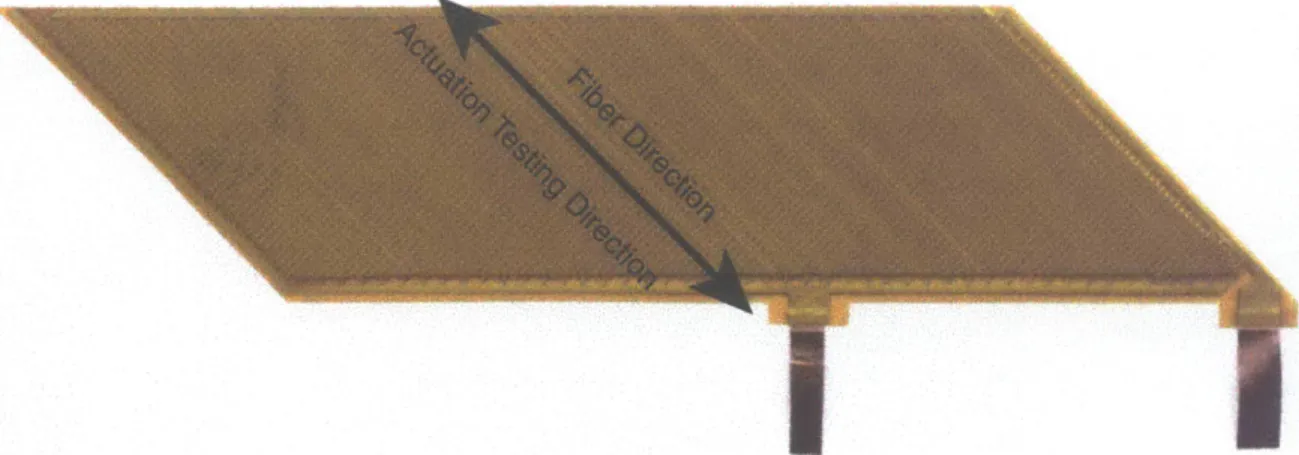
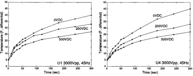
Simple constraint model . . . . Actuator and constraint stress-strain plots . . AFC standard test coupon . . . . Setup for coupon lamination in the hotpress . Actuation testing direction . . . . Blade pack lamination data . . . . Reduction factors for high and low free strain AFC packs Time histories of heating of unlaminated blade packs . . . Effect of DC offset on blade pack heating . . . . Current draw of unlaminated packs U2 and U3 . . . . Current draw of laminated packs 1H and 1L . . . . Peak current draw vs. frequency . . . . . . . 44 . . . 44 . . . 47 . . . 49 . . . . 53 . . . . 55 . . . . 56 . . . 60 . . . 61 . . . 62 . . . 62 . . . 63 11 3-1 3-2 3-3 3-4 3-5 3-6 3-7 3-8 3-9 3-10 3-11 3-12
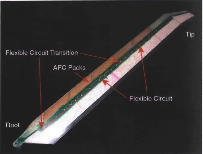
3-13 3-14 3-15 3-16 3-17 3-18 3-19 3-20 4-1 4-2 4-3 4-4 4-5 4-6 4-7 4-8 4-9 4-10 4-11 4-12 4-13 4-14 4-15 4-16 4-17 4-18 4-19 5-1 5-2
Active materials rotor blade showing the routing of the fle Typical blade actuator pack . . . . Electrode leadout tab detail . . . . Blowup of flexible circut . . . . Blade section 4.0 drawing . . . . Blade section 4.0 spar layup . . . . Protection of electrode tab during spar cure . . . . Hardback manufacturing . . . . Hardback mounted in blade mold . . . . Section 4 spar...
AMR blade fairing assembly . . . . Flexible circuit routing on fairing foam core . . . . Blade section 4.0 with connections to flexible circuit made Schematic of flexible circuit transition from web to fairing
Connection area filler material during fairing cure . . . .
Completed blade section 4.0 . . . . Active area of completed blade section 4.0 . . . . Twist measurement schematic . . . . Blade section 4.0 actuation . . . . Active Material Rotor (AMR) blade . . . . AM R blade layup . . . .
Effect on DC offset on current draw . . . .
Equivalent circuit model for the AFCs . . . . . Fit of R-C model to current-voltage data . . . . Capacitance and resistance for laminated packs Dissipated AFC current . . . . Power draw data for laminated packs . . . . Tan6 data for laminated packs . . . .
Performance envelope for AMR blade . . . . .
xible circuit . . . . 78 . . . 80 . . . 80 . . . 82 . . . 84 . . . 85 . . . 86 . . . 87 . . . 87 ... 89 . . . 90 . . . . 91 . . . . 91 . . . 92 . . . 92 . . . 95 . . . 97 . . . 97 . . . 98 . . . 103 . . . 103 12 . . . 6 4 . . . 6 5 . . . 6 6 . . . 6 8 . . . 6 9 . . . 7 0 . . . . 7 1 . . . . 7 4
5-3 5-4 5-5 5-6 5-7 5-8 5-9 5-10 5-11 5-12 5-13 5-14 5-15 5-16 5-17 5-18 5-19 5-20 5-21 5-22 5-23 5-24 5-25 5-26 5-27 5-28 5-29 5-30 5-31 5-32
AMR AFC actuator pack . . . . Internal flexible circuit . . . . AMR blade crossection showing the flexible circuit .
Oversized solder pad cutout in flexible circuit . . . .
Rotor hub with flex circuit routing . . . . AMR external flexible circuit . . . . Power distribution board . . . .
Power distribution board with flexible circuits . . . .
Process blade actuator packs allocation . . . .
Completed AMR blade . . . .
AMR blade root . . . .
AMR blade midspan detail . . . .
AMR blade tip detail . . . .
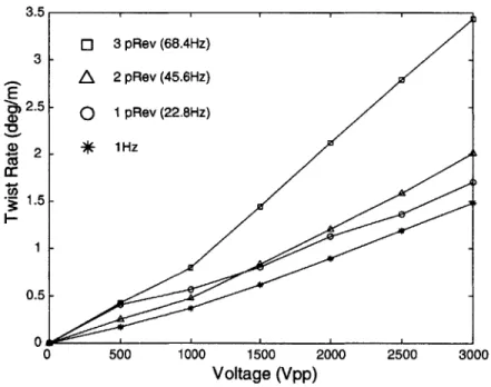
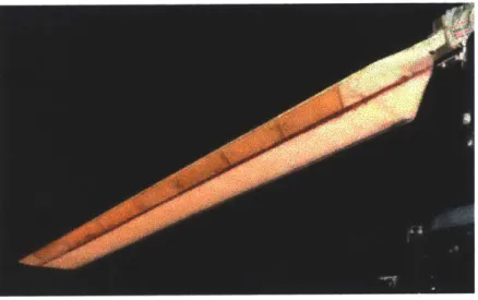
Actuation testing setup . . . . AMR blade clamped at root . . . . Actuation of the process blade at 1Hz . . . . AMR blade actuation data at several frequencies. . . AMR blade twist versus span data . . . .
Depoling of blade AFCs . . . .
Effect of a DC offset on the depoling behavior of the Torsional stiffness testing setup . . . . Blade current draw . . . . Frequency dependence of blade heating . . . . Voltage dependence of blade heating . . . . DC offset dependence of blade heating . . . . Effect of DC offset on current draw . . . .
Blade capacitance and tan . . . .
Actuator pack failure schematic . . . . Blade crossection . . . . Crossection of AFC failure . . . .
13 . . . 104 . . . 10 5 . . . 106 . . . 10 7 . . . 108 . . . 108 . . . 109 . . . 109 . . . 111 . . . 113 . . . 114 . . . 115 . . . 115 . . . 118 . . . 118 . . . 120 . . . 120 . . . 12 1 . . . 122 blade AFCs . . . 122 . . . 123 . . . 124 . . . 126 . . . 126 . . . 127 . . . 127 . . . 128 . . . 130 . . . 133 . . . 133
5-33 Crossection of connections . . . . 5-34 Crossection of flexible circuit transition . . B-1 Section 4.0 parts list . . . . B-2 Section 4.0 drawing . . . . B-3 Section 4.0 flexible circuit design . . . . B-4 Drawing of outboard tip fitting . . . .
B-5 Section 4.0 electrode pattern . . . .
. . . 13 3 . . . 13 3 . . . 1 5 4 . . . 15 5 . . . 1 5 6 . . . 1 5 7 . . . 15 8
C-1 Average bending stiffness of the AMR blade . . . 160
C-2 Transfer function from drive voltage to twist rate . . . 162
C-3 Transfer function from drive voltage to blade curvature . . . 162
C-4 AMR blade average spectrum in twist mode . . . 163
C-5 AMR blade average spectrum in bending mode . . . 163
C-6 Second bending mode of the AMR blade . . . 164
C-7 Second bending mode of the AMR blade. . . . 164
C-8 Third bending mode of the AMR blade . . . 165
C-9 Third bending mode of the AMR blade . . . 165
C-10 Fourth bending mode of the AMR blade . . . 166
C-11 Fourth bending mode of the AMR blade . . . 166
C-12 First torsion mode of the AMR blade . . . 167
C-13 First torsion mode of the AMR blade . . . 167
C-14 Crossections of the AMR blade . . . 168
C-15 Crossections of the AMR blade . . . 169
C-16 AMR flexible circuit drawing . . . 170
C-17 Location of the solder pads in the AMR flexible circuit . . . 171
D-1 Flexible circuit flareout trimming . . . 175
D-2 Flexible circuit connector crimping . . . 176
D-3 Flexible circuit crimp connector soldering . . . 176
D-4 Pin insertion into crimp connectors . . . 177
D-5 Flex circuit connector mold . . . 177 14
D-6 Flexible circuit connector potting . . . 178
E-1 eT and tan 6 information on PZT-5A, PZT-4, and PZT-8 . . . 180
F-i F-2 F-3 F-4 F-5 F-6 F-7 F-8 F-9 F-10 First generation blade damage map . . . . Crossection of first generation blade at BS19 Voids testing spar assembly . . . . Voids testing spar layup . . . . Spar crossectioning . . . . Void locations in test spar . . . . Picture of voids in the test piece . . . . Void detail . . . . Voids comparison . . . . Moisture voids . . . . F-11 Foam block 1: Crossections 1-4, outboard view. . . F-12 Foam block 1: F-13 Foam block 2: F-14 Foam block 2: F-15 Foam block 3: F-16 Foam block 3: F-17 Foam block 4: F-18 Foam block 4: F-19 Foam block 5: F-20 Foam block 5: F-21 Foam block 6: F-22 Foam block 6: Crossections 1-4, inboard view. . . . Crossections 5-9, outboard view. . . Crossections 5-9, inboard view. . . . Crossections 10-14, outboard view. . Crossections 10-14, inboard view. Crossections 15-20, outboard view. . Crossections 15-20, inboard view. Crossections 21-25, outboard view. . Crossections 21-25, inboard view. Crossections 26-29, outboard view. . Crossections 26-29, inboard view. . . . 182 . . . 182 . . . 184 . . . 184 . . . 185 . . . 186 . . . 187 . . . 188 . . . 189 . . . 190 . . . 190 . . . 19 1 . . . 19 1 . . . 19 1 . . . 192 . . . 192 . . . 192 . . . 193 . . . 193 . . . 193 . . . 194 . . . 194 15
List of Tables
3.1 3.2 3.3 3.4 3.5 3.6 3.7Nominal low stress AFC and E-glass properties . . . . Coupon lamination testing test matrix . . . . Summary of coupon testing, control and heat-only specimens Summary of coupon lamination testing, cure pressure results Blade pack lamination testing pack description . . . . Summary of blade pack lamination testing . . . . Heating and current draw testing pack description . . . .
5.1 Failure history of process blade actuator packs. . .
A.1 Results of coupon testing . . . . A.2 Capacitance data for test coupons . . . . A.3 Resistance data for test coupons . . . . C.1 Actuation data for process blade packs . . . . E.1 Piezoelectric ceramic properties . . . .
17 . . . . 43 . . . . 47 . . . . 51 . . . . 51 . . . 53 . . . 54 . . . 59 130 150 151 152 160 179
Chapter 1
Introduction
Integrally actuated helicopter rotor blades are being developed by MIT and Boeing Helicopters [Rodgers, 1998; Derham, 1996; Schmidt, 2000]. Piezoelectric fibers, in the form of Active Fiber Composites (AFCs), are incorporated into the skin of the blades to enable active deformation
of the structure. A prototype integrally actuated blade was developed in 1998 by Rodgers.
This blade demonstrated that the concept of embedding AFCs in a helicopter blade was
fea-sible, but fell short of expected performance levels [Rodgers, 1998]. This thesis will focus on
the further development of integral actuation technology for helicopter rotor craft structures. This development work will focus on several problems that were encountered in the Rodgers blade, and will involve improving the blade manufacturing procedure and acquiring a better understanding of the behavior of the active material embedded in the blade.
1.1
Motivation
Vibration has historically been a great concern of helicopter manufacturers, pilots, and
passen-gers. Much work has been done to reduce vibration over the past 50 years, and as a result
vibratory loads in helicopters have been steadily decreasing. Two criteria have driven the
continued effort to dampen vibration in helicopters: human factors, such as ride comfort and cabin noise, and maintainability and functional reliability [Reichert, 1980].
Non-uniform airflow through the rotor in forward flight causes periodic vibratory aerody-namic forces on the rotor. These vibratory loads usually exhibit themselves as n-per revolution
(n-PRev) excitation forces on the hub, where n is the number of blades in the rotor. Harmon-ics of this frequency are also excited, leading to a broader spectrum of vibratory loads [Braun,
1984].
Atmospheric turbulence, retreating blade stall, blade vortex interaction, and blade fuselage
interference are contributing factors in the generation of rotor vibration [Ham, 1987]. These
sources of vibration apply moments and forces to the hub of the rotor, and vibration is trans-ferred to the fuselage through the drive shaft and motor.
Passive damping has been used for many years to attempt to reduce the vibratory loads
transmitted from the rotor to the fuselage. Passive damping work has focused on altering
the dynamics of the rotor and of the fuselage to cancel out vibration at certain frequencies. Pendulum absorbers can be mounted at the root of the blade to create a node at a given
frequency. 50% reduction in vibratory loads have been achieved with such systems [Amer,
1974]. Isolation systems can also be implemented between the fuselage and the drive unit and rotor. These systems alter the dynamics of the vehicle to create a point of zero vibration at a given frequency [Desjardins, 1978].
The disadvantage of using passive dampers to reduce vibration in helicopters is that passive
dampers are generally tuned to a specific frequency. Since vibration usually occurs over a
wider spectrum of frequencies, including many harmonics of the primary rotor vibration, passive vibration isolation or damping can only have limited success.
The use of active vibration control can be used to dampen vibration over a larger range
of frequencies. Two main approaches are taken towards active vibration control: Higher
Harmonic Control (HHC) and Individual Blade Control (IBC). HHC involves exciting all
blades with the same signal to attempt to counteract vibratory airloads. This actuation
method is usually implemented through oscillatory swash plate motion to cause periodic pitch
control [Shaw, 1981]. Vibration reduction is mostly concerned with harmonics of the rotor
frequency. Due to rotor symmetry, only these harmonics are transmitted to the fuselage.
HHC is therefore well suited for vibration control. However, for noise control, a much wider spectrum must be considered since structural filtering does not occur in each of the individual
blades [Prechtl, 2000]. Therefore, HHC is not a practical method for simultaneous noise
reduction and structural vibration reduction.
IBC involves controlling each blade separately. Each blade has an actuator mechanism and an individual feedback loop to allow control of each blade independently. This provides more degrees of freedom of the rotor than HHC allows, leading to more effective reduction of
vibration [Jacklin, 1995]. Individual blade control can be implemented at the hub through
replacing the rotating pitch links with hydraulic actuators. These actuators can be used to
apply small pitching motions at high frequencies independently to each blade [Swanson, 1994].
Alternatively, IBC can be implemented through blade mounted actuators. This
imple-mentation allows vibration reduction at the source of the disturbance [Reichert, 1980]. Blade mounted actuator technology has seen rapid growth due to the development of smart actuation technology. The use of smart materials, such as piezoelectric ceramics and shape memory al-loys (SMA), allows direct conversion of electrical energy to mechanical energy. This eliminates the need for complex mechanisms and hydraulic systems to actuate the blades at high
frequen-cies. Induced strain actuators have large force and energy capabilities, but they have very
small strokes. Therefore, in most cases, displacement amplification mechanisms must be used
to create usable actuator deflections [Giurgiutiu, 2000]. A great advantage to blade mounted
actuators is that they are not critical flight elements. A failure of an actuator is therefore not a catastrophic event since it does not compromise the robustness of the vehicle, as, for example, a pitch link actuator failure would [Prechtl, 2000].
A direct approach to counteracting vibrational airloads on the rotor is distributed twist actuation of the blades [DuPlessis, 1995]. See Figure 1-1. Embedding active material directly in the skin of the blades can eliminate the need for stroke amplification mechanisms and transform the entire blade structure into an actuator. Distributed actuation has several advantages. Since there are no moving parts, such as displacement amplification mechanisms or flap assemblies,
maintenance is simplified. The lack of mechanisms and flaps in the blade allows actuation
without adding drag due to extra aerodynamic surfaces. Distributed actuation also means
redundancy in actuation. The active material is incorporated into the blade skin in several
packs. If one or more packs fail, the remaining packs can continue to actuate the blade,
although at a reduced level.
Active Fiber Composites (AFCs) have been developed for the purpose of embedding in
oriented at a 45 angle to the blade span can be used to create a distributed twisting moment along the span of the blade. This moment causes the blade to twist, changing the lift of the blade, enabling implementation of IBC.
A blade was developed by Rodgers in 1998 that implemented this technology with mixed
success. The blade experienced several actuator failures due to manufacturing and
opera-tional stresses. These failures were partly caused by actuator material immaturity and blade
manufacturing difficulties. Due to actuator failures, the drive voltage of the Rodgers blade
was limited to 2000Vpp, instead of the full design voltage of 4000Vpp. The lowered voltage, along with failure of approximately half the actuator packs prior to hover testing, limited the blade actuation level to approximately 25% of the design level. The blade did however demon-strate that a structurally sound active blade could be built and actuated in a realistic hover environment [Rodgers, 1998]. More information on actuator failures is provided in Chapter 2.
1.2
Active Fiber Composites
Active Fiber Composites use piezoelectric fibers for in-plane actuation. Piezoelectric materials
exhibit coupling between electrical and mechanical behavior. Mechanical displacement will
cause charge to flow through the material, and the application of an electric field will cause mechanical deformation. Extensive information on piezoelectric ceramics have been published,
and will not be discussed here [Bent, 1997; Ghandi, 1998; Jaffe, 1971; Berlincourt, 19XX].
Most piezoelectric actuators are based on piezoelectric wafers, either as single wafers or as stacks of wafers. AFCs, on the other hand, consist of piezoelectric fibers, 0.005" to 0.01" thick, embedded in an epoxy matrix. The ceramic fibers are brittle and tend to crack at relatively low strains. Surrounding the fibers with an epoxy matrix significantly improves strength and toughness properties of the actuator. The matrix reinforces the fibers, allowing the actuator to withstand higher strains than the individual fibers could withstand. The epoxy matrix provides a path for load transfer around fiber cracks. This keeps a crack on one fiber from propagating to other fibers and causing extensive damage to the AFC. This presents an improvement over actuators based on ceramic wafers, which are prone to macroscopic and catastrophic damage resulting from cracks in the ceramic [Jones, 1999].
Passive Plies
Weights
Foam Core
Active Plies
Aerodynamic
Fairing
Figure 1-1: Active blade concept. Active plies are embedded among the passive plies. In
plane actuation of active plies oriented at
+/-
450 induces a torsional moment along the spanof the blade, twisting the blade.
AFCs are equipped with an interdigitated electrode pattern. See Figure 1-2. This electrode pattern orients the electric field along the fiber, taking advantage of the primary piezoelectric
effect, the expansion of the ceramic in the direction of the applied field. See Figure 1-3.
Excitation of the actuator therefore causes in-plane actuation in the direction of the fibers. This actuation mode is ideal for use in adaptive composite structures.
The AFCs are manufactured in "packs". These packs are of a given geometry, which
is application dependent. For example, the AMR blade, which will be discussed in detail
in Chapter 5, incorporates 24 individual packs into the blade. These packs are electrically
independent, so if one pack fails, it will not affect the other packs.
... ... ... ... .. . .. ...
ar-Web
Figure 1-2: Active fiber composites (AFCs) consist of piezoelectric fibers embedded in an epoxy matrix, surrounded by an interdigitated electrode pattern. The electrode pattern orients the electric field along the fiber, taking advantage of the primary piezoelectric effect of the fibers.
See Figure 1-3.
Electrode Fingers
Figure 1-3: Schematic representation of the electric field in an individual fiber. Interdigitated electrodes orient the electric field along the fiber. This allows the actuator to take advantage of the primary piezoelectric effect, the extension in the direction of the applied field. In plane actuation of the AFC is achieved using this actuation method.
...
1(
A-*
1.3
Objectives
The main objective of this thesis is to further develop and improve integral actuation technology
using AFCs and to incorporate this technology into a composite rotor blade structure. Two
main areas will be addressed: " Actuator understanding " Manufacturing improvements
Improving and simplifying the manufacturing procedure of the active blades is important
to creating more robust and better performing helicopter blades. Since the actuators are
embedded in the skin of the blade, they can not be replaced. Therefore, it is important that
actuator failures be minimized. Actuator failures can occur either during manufacturing or
during operation. Improving the design of the integral actuation system, including AFCs,
actuator leadouts, and high voltage lines, will reduce the number of failures that occur during
manufacturing. It will also create a more robust blade, minimizing the number of actuator
failures that occur during operation.
In designing integrally actuated blades that meet actuation and structural requirements, it is necessary to be able to accurately predict the behavior of the actuators when embedded in the blade. Historically, modeling of the blades has been difficult because of the unpredictable
nature of the AFCs. A better understanding of the high field actuation non-linearities of the
AFCs is necessary to improve the accuracy of blade modeling.
Determining the electrical behavior of the AFCs embedded in the blades will provide
valu-able information necessary for practical application of the AFCs. Voltage and frequency
dependence of actuator current draw will be studied. This information will help determine the amount of current necessary to drive the blades at a given voltage and frequency, and will help guide the selection of amplifiers to be used in windtunnel testing of the blades.
1.4
Approach
Lessons learned in the Rodgers blade will be applied to develop the new design of the integral
and improvements made. The main improvement will involve redesign of the power bus, the
set of power leads that bring power to the actuators. Manufacturability of the connections
to the actuators will be improved and simplified. Hypotheses for actuator failures presented
by Rodgers will be studied and appropriate changes will be applied to the new design of the integral actuation system [Rodgers, 19981.
Actuator understanding will be developed through testing of individual AFC packs. Lami-nation testing will be performed to determine the effects of constraint on the actuation authority of the actuators. An equivalent circuit model will be developed to study the current draw of the AFCs. This model will provide information on the voltage and frequency dependence of AFC capacitance and dielectric loss.
Finally, an active blade will be designed and bench tested. Bench testing will include
actuation testing, mechanical testing, and electrical testing. The results will give further
information on mechanical and electrical AFC behavior, and will show how the behavior of individual AFCs correlates with the behavior of the blade structure.
1.5
Summary of Document
Chapter 2 will describe the current state of integral actuation technology. The first generation
integrally actuated blade will be presented. Actuation capability and a summary of hover
testing will be given. The problems associated with the first generation blade and their impact on the performance of the blade will then be discussed. Hypotheses for the numerous actuator failures that occurred in this blade will be discussed, focusing mainly on blade manufacturing.
Chapter 3 will present the actuator characterization work performed to better understand the behavior of the embedded actuators. AFC coupon and blade packs are tested to determine the effects of lamination on the AFCs. Significant variations in laminated performance are seen
in the packs. Recommendations on reduction factors to be used in modeling the integrally
actuated blades will be given. Extensive testing is performed on blade packs to understand
the electrical behavior of the AFCs. Analysis of the high current draw and heating of the
AFCs will be presented. Drive voltage and frequency dependence of actuator pack capacitance and dielectric loss factor will be quantified using a simple equivalent electrical circuit. It will
be shown that both the pack capacitance and dielectric loss factor increase significantly as the
drive voltage is incresed. Recommendations for testing of the integral blades will be given
based on the data presented in this chapter.
Chapter 4 will describe the work done to improve the manufacturing of the blade. Significant changes are made to the power bus design and to the connections to the actuators. The power bus and connections to the actuators is moved from the web of the blade to the surface of the fairing. The design of the actuator leadouts, the flexible circuit power bus, and the connections between the two will be presented. To test the new design, manufacturing studies are conducted. These manufacturing studies include building a pair of short blade sections incorporating the
new design. The new design was shown to be a viable design for incorporation into a full
model-scale active blade.
Chapter 5 will present the Active Material Rotor (AMR) blade being developed for wind
tunnel testing at Boeing, Philadelphia. The implementation of the design changes discussed
in Chapter 4 will be the main focus of the first part of this chapter. The second part of the
chapter will focus on the testing of the blade. This testing will include actuation testing,
electrical testing, and mechanical testing. The blade achieved a 2.30 /m twist rate, compared
to a 2.50 /m model prediction. Analysis of actuator failures will be conducted. Mechanical
testing will give the torsional and bending stiffnesses of the blade, and show correlation to
models. The current draw was greater than expected, as was the heating, but both were
in-line with expectations based on individual pack testing. Electrical data will also include the blade capacitance and loss factors as a function of voltage. These results will be compared to the results of individual actuator pack testing.
Chapter 6 will conclude the thesis by summarizing the accomplishments of the work and providing recommendations for changes to the actuator design, blade design, and manufacturing procedure. Appendices are included to provide blade manufacturing information and actuation data that was not included in the body of the thesis.
Chapter 2
State of Integral Actuation
Technology
This chapter will discuss the current state of blade mounted actuation technology, focusing on integral actuation using Active Fiber Composites. Past work on the actuators and on the blades will be described. Other blade mounted actuator technologies will be discussed briefly.
2.1
Overview of Blade Mounted Actuator Technologies
Smart material actuators have helped overcome the size, weight, and complexity problems that have limited the incorporation of hydraulic and electromechanical actuators into helicopter
blades (Straub, 1996]. This section will provide a brief overview of various smart material
approaches to blade mounted actuation.
A discretely actuated blade has been developed at MIT by Prechtl and Hall, in conjunction with Boeing Helicopters. This actuation scheme is based on using a piezoelectric stack actuator with a displacement amplification mechanism to drive a trailing edge flap. The blade has had success in vibration reduction studies, virtually eliminating vibration at several rotor harmonics simultaneously [Prechtl, 2000b].
Prahlad and Chopra at the University of Maryland are developing a rotorblade that in-corporates Shape Memory Alloy (SMA) into the structure. The change in Young's Modulus of the material as a function of temperature allows the natural frequencies of the blade to be
changed. The dynamic properties of the rotorblade can therefore be tuned to varying blade
environments [Prahlad, 2000]. The actuation capability of SMA technology is used to create
variable camber blades. By embedding SMA in the blade skin, the camber of the blade can be actively changed to alter the aerodynamic properties of the airfoil [Roglin, 1994].
Spangler and Hall at MIT developed a flap actuator based on a piezoelectric bimorph. The
tip displacement of the bimorph actuator is used to drive a trailing edge flap through an
amplification mechanism. This actuator is simple, lightweight, and compact, and is therefore
suited well for integration into a helicopter blade [Spangler, 1990]. Walz and Chopra, at the
University of Maryland, have developed a similar actuator [Walz, 1994].
An actuator taking advantage of induced shear properties of piezoceramics is being devel-oped by Centolanza and Smith at Pennsylvania State University. The actuator incorporates electrodes in the tube that allow the shear piezoelectric effect to be excited, twisting the tube along the length. The piezoceramic tube is used to drive a trailing edge flap through a coupling mechanism [Centolanza, 2000].
A full scale discrete actuator is being incorporated into an MD-900 blade by Boeing
Heli-copters, Mesa. This blade incorporates a piezo stack actuator for high frequency actuation,
and an SMA actuator for low frequency trim tab actuation [Straub, 2000].
Integrally actuated blades based on piezoelectric ceramic actuators have been developed by MIT, Boeing, NASA, and the University of Maryland. The University of Maryland blade
incorporated piezoelectric wafers within the skin of a rotor blade. The wafers were sliced
into strips and were oriented at 450 to the blade span. This program had moderate success, achieving only small deflection angles of the blade [Chen, 1994].
With the development of AFCs, integral actuation using piezoelectric materials has become
a more viable actuation technology. AFCs are more easily incorporated in the composite
structures, due to their small thickness, their flexible nature, and their in-plane actuation capability.
2.2
Integrally Actuated Blades
2.2.1
Actuator
AFC actuators have been under steady development over the past decade. The material system has become more reliable and manufacturability has been improved [Strock, 1999]. The cost of
the actuator system has also decreased significantly.
Until 1998, AFCs had been manufactured using copper-Kapton electrodes. These electrodes consisted of an etched interdigitated copper electrode pattern on a Kapton substrate [Rodgers, 1998]. Due to cost and manufacturing difficulties, the copper-Kapton electrodes were abandoned in favor of screen printed silver ink electrodes. These electrodes are screen printed onto a Kapton substrate using conductive ink. Because the screen printed electrodes are more malleable, they conform better to the shape of the fibers, providing a greater contact area between the electrodes and the fibers. This increases the actuation authority by introducing more of the electric field
into the fiber [Wickramasinghe, 2000].
The fibers that were used in the AFCs until late 1999 were 0.005" diameter fibers. These fibers were manufactured by CeraNova Corporation'. AFCs manufactured with 0.005" diameter fibers had a total thickness of between 0.008" and 0.009". For comparison, the passive plies used in the blade are all under 0.010" in thickness. The AFCs are therefore thin enough to be easily incorporated into the skin of the blades.
To improve manufacturability and scalability to full size, 10 mil fibers were introduced in the fall of 1999 as a possible alternative to the 5 mil fibers. AFCs manufactured with 0.010" fibers have a total thickness of 0.013". Properties of the 0.005" and 0.010" fiber AFCs are presented in Chapter 3. There are several advantages to using 0.010" fibers. Since one of the determining factors of the actuation authority is the volume of active material, only one quarter as many 0.010" fibers as 0.005" fibers are necessary to create a given actuation authority. Since the manufacturing of fibers, and not the bulk material or size of the fibers, is the most significant factor driving the cost of the AFCs, using larger diameter fibers translates to large cost savings. The 0.010" fibers, being straighter than the 0.005" fibers, can also help achieve line fractions, or fiber density, higher than in the 0.005" fiber AFCs. Line fractions as high as 90% are achievable
31 'CeraNova Corporation, Franklin, MA.
with the larger fibers, further increasing actuation authority [Pizzocchero, 1999].
However, the larger fibers have some drawbacks as well. Due to the bulk of material in the 0.010" diameter fibers, the chances of defects in the fibers is increased. These defects may lead to fiber cracking. To compound the problem of fiber cracking, the higher attainable line fractions limit the amount of epoxy matrix around the fibers. The load transfer path around cracks is therefore compromised, and cracks may be able to propagate from one fiber to another, causing macroscopic damage to the composite [Jones, 1999]. Studies have shown that the 0.005" diameter fiber AFCs retain their mechanical properties to much higher strain levels than the 0.010" fibers, indicating that damage propagation from one fiber to another may be a problem in 10-mil AFCs [Wickramasinghe, 2000].
2.2.2
Blade Scaling
All work on integral actuation has been performed on scaled down model helicopter blades.
Two scaling methods have been used in designing integral blades: Froude scaling and Mach
scaling. Froude scaled blades have realistic strains and blade accelerations, but lower dynamic
stress levels than full scale blades [Bielawa, 1992]. Froude scaling has been shown to be best
suited for aeroelastic stability studies [Friedmann, 1998]. A Mach scaled blade has the same
tip speed as a full scale blade. Mach scaling ensures that compressibility effects at the leading edge of the blade are realistic and that stresses experienced by a model scale blade are equal to the stresses experienced by a full size blade. [Bielawa, 1992]. Mach scaling has been shown to be best suited for vibration control studies of rotor blades [Friedmann, 1998].
2.2.3
MIT/NASA Langley Integral Blade
MIT and NASA built an integrally actuated blade in 1999, known as the Active Twist Rotor (ATR). This blade was based on a NACA-0012 airfoil, with a chord length of 4.24" and a rotor
radius of 55". The blade was Froude scaled [Cesnik, 1999]. This blade was hover tested
in the NASA Langley Transonic Dynamic Thnnel. [Shin, 1999]. The blade incorporated 24
actuator packs into the spar skin. These packs had 0.005" fibers and screen printed electrodes.
Two plies of actuators were used, one ply oriented at +45' and one ply oriented at -45*. The
manufacturing procedure for this blade was similar to the manufacturing procedure used in the
MIT/Boeing integral blade. This manufacturing procedure will be described in Section 2.2.4. The experimentally determined twist rate at 2000Vpp, OVDC was 1.00 /m. The ATR blade experienced 5 actuator pack failures during testing, all due to internal pack failure [Shin, 1999].
2.2.4
MIT/Boeing Integral Blade
A 1/6 scale, 60.6" radius, Mach scaled CH-47D integrally actuated rotor blade was built by
MIT and Boeing in 1998. The blade was built at MIT and hover tested in the MIT hover test
facility.
The CH-47D blade consisted of a D-spar and an aerodynamic fairing. The spar provides the structure and the strength of the blade, while the fairing is for aerodynamic purposes only.
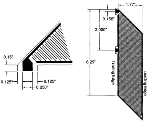
The spar layup is seen in Figure ??. The fairing consisted of a single ply of 450 E-glass with
a few strips of graphite at the trailing edge to add strength and chordwise bending stiffness. The vertical surface on the back of the spar that forms the interface surface with the fairing is called the web. See Figure 1-1. The web in the CH-47D blade consists of 3 plies of 45' E-glass and contributes a significant portion of the blade torsional stiffness [Cesnik,1998].
The CH-47D blade incorporated 42 0.005" fiber AFC packs into the skin of the spar. These packs were divided into 3 plies, with two plies oriented at
+45*
and one ply oriented at -45'. See Figure 2-1.During manufacturing of the Boeing/MIT integral blade, electrical connection to 11 of 42 actuator packs was lost. Several actuators failed during testing. After initial bench testing, 20 actuator packs were operational. 12 actuators were operational at the end of hover testing. A full failure history has been published [Rodgers, 1998].
Figure 2-3 shows actuation data for the first generation integral blade. The blade opera-tional voltage was limited after several actuator pack failures had occurred to prevent further damage to the blade. A half span blade section that was built before the full blade shows the actuation authority attainable with the design [Rodgers, 1998].
The MIT/Boeing blade showed a 0.80 /m twist rate at 2000Vpp, OVDC, with 69% of actu-ators working. A Boeing FEM model predicted an actuation level of 1.30 /m for this configu-ration through the uniform section of the blade, from 0.34R to 0.65R. The model prediction assumed linear constraint behavior for the material. In other words, the actuation level varied
0.15R
~packs
lead-lag pin ~ ~ ~ ~ ~wire trough
active plies web flex circuit
fairing
trailing edge
1.92
4
IM7 Graphfte @0 dog E-glass 0 45 dog AFCO @45 deg E-glas @ 45 dog AFC O -45 dog S-glass @0 dog AFC 0 45 dog E-glass @ 45 dog
Figure 2-1: Geometry and layup of the MIT/Boeing integrally actuated rotor blade. The layup shown represents the layup of the typical active section of the blade. The blade has plies of +45' AFCs and one ply of -450 AFCs.
Figure 2-2: Integral blade on the MIT hover test stand. AFCs can be seen in the spar skin. . .. . ... .... . ...
2. I I I I 2 -+ + 1.5 0.5-- -0 - -- --I 00 1 B1 +v tonda 0 0 0.5 . 1 1.5 2 2.5 3 3.5 4
Peak to Peak Voltage (kV)
Figure 2-3: Blade section and full blade twist rates. The maximum drive-voltage of the Rodgers blade was limited to 2000Vpp. A blade section that was built was actuated at 4000Vpp. The blade data was taken with 69% of the actuators operational. The section data was taken with
10 of 12 actuators operational [Rodgers, 1998]. The model predictions are based on Boeing FEM predictions. The "corrected" model results incorporate a correction factor to account for
high field non-linearities in the AFCs [Weems, 1998].
linearly with the constraint level of the material. However, it was shown by Rodgers that
this assumption may be inaccurate. Individual actuator pack testing had shown that a 0.70 correction factor should be applied to the twist rate predictions based on free actuation levels. This brought the predicted twist level to 0.910 /m, only 14% over the measure twist rate at
2000Vpp [Weems 1998].
A transfer function of the Rodgers blade in hover is shown in Figure 2-4. This transfer is from input voltage to coefficient of thrust, and gives an indication of the actuation authority through the frequency spectrum [Rodgers, 1998].
While the Rodgers blade showed that the concept of embedding AFCs in a rotor blade was feasible, the blade experienced numerous actuator failures and therefore fell short of expected actuation authority. A total of 34 of the 48 actuator packs had failed or had lost electrical
contact by the end of testing. 11 packs became disconnected during the blade manufacture.
... ...... ...
10-2 10 106 0 -500 -1000 -1500 0 50 Frequency (Hz) 100 150
Figure 2-4: Transfer function from input voltage to coefficient of thrust of Rodgers blade in
hover [Rodger, 1998].
4 deg 4 deg
Another 8 packs were lost due to connection loss or due to failures in the power bus during testing. The remaining 15 packs failed internally due to short circuits[Rodgers, 1998].
Figure F-1 shows the failure map of the Rodgers blade. This figure includes all failures
that occurred during manufacturing and operation. The damage map shows numerous core
voids were observed in the core of the blade when the blade was cut into sections. These core voids correlated with the location of internal strain gages in the blade indicating that one of
the chemicals used in the blade instrumentation was outgassing during the cure. The work
that was done to correct the problem of core voids will not be discussed in this thesis, but will presented in Appendix F.
The loss of the actuator packs in the Rodgers blade can be attributed to immaturity of the material system and to the difficulties encountered when manufacturing the blade. The main source of manufacturing problems were the electrical connections to the actuator packs. The connections were made using a solder joint that proved difficult to make because of its location in the blade and the types of solder used.
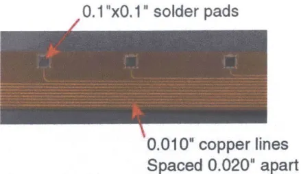
Power is supplied to the actuators through a flexible circuit. The flexible circuit consists of multiple copper lines sandwiched between two layers of Kapton. An acrylic matrix acts as an insulator between conductive lines. Each copper line is designed to carry up to 0.5 amps at
4000V.
Figure 2-5 shows the flexible circuit design used in the Rodgers blade. The actuator packs used in the blade had copper electrodes. Before the spar cure, a copper pad was mounted to the electrode tab to reinforce the tab and reduce the risk of breakage during the cure. This reinforcement pad was mounted to the electrode tab with a regular lead/tin solder, with a melting point of 450'F. The electrode flaps were bent onto the web of the blade during the
spar cure. They were cured in place, and Guaranteed Non-Porous Teflon2 (GNPT) tape was
placed over the electrode pads to ensure that the conductive surface is left exposed.
Following the spar cure, the flexible circuit was placed against the web and the exposed copper electrode flaps. The connections were made, supplying heat to the hidden solder con-nection through an auxiliary copper strip which is trimmed off following the concon-nection. A low temperature (290'F) indium solder was used to make the connection from the electrode
2
GNPT, American Durafilm Co., Holliston, MA. 37
Auxilliary Copper Strips For Heat Conduction
Electrode Flap
Figure 2-5: Connections in the Rodgers blade are made along the web. The electrode tabs
are bent onto the web, the flexible circuit is placed against the web. Heat is conducted into the connections through an auxiliary copper strip. The connection is hidden, and can not be
inspected. X7 T VX' 2 X'3 X 4~ 5~i±~iLA(iJ I UPPER " core void BS9.093 17 21 25 29 33 37 41 45 49 53 57 60.619 -- section cut o strain gage 5 8 > delamination (inner) 8"" m Co < delamination (outer) 4
*
pack electrical failure> electrode d BS).H'I0 17 21 5 29 3 7 141 45 49 13 5 6C.619
LOWER
Figure 2-6: Damage map of the Rodgers blade. [Rodgers, 1998]
re ........ ...
)V Z)V i xe, -4 M - M A M--7--M --- I
Electrode Tabs
tab to the flexible circuit. This solder was used to prevent melting of the solder joint between
the reinforcing pad and the electrode tab. However, this solder also had a lower strength
than the regular solder, making the connections prone to failure. Following the flexible circuit attachment, the fairing was assembled and cured, completing the integral blade [Rodgers, 1998]. The manufacturing procedure described above may have lead to broken connections or short circuits between connections or power lines.
First, the low temperature solder joint between the electrode tab and the flexible circuit may have broken during manufacturing and operation because of the lower strength. Also, the low temperature solder may have been melted by localized overheating of the blade molds. The blade is cured at 250'F, but because of inadequate thermal control, it is believed that significant localized overheating may have occurred in the blade mold, with spots reaching temperatures as high as 300'F. The connections made with the low temperature solder may therefore have melted and come apart.
Second, the electrode flaps were bent onto the web, making connection to the flexible circuit difficult. The flexible circuit was brought against the web, hiding the connection area. Heat conduction through the auxiliary copper strip into the connection area may have been inade-quate. This scenario also prevented inspection of the solder joint. As soon as some part of the solder joint was made, it became impossible to inspect the connection. Proper solder melting and flow could not be verified.
The sharp bend in the electrode tab may have created a stress concentration in the electrode tab. This stress concentration may have damaged the electrode tab during the cure or during operation.
Third, the flexible circuit consisted of six separate layers bonded together. While each layer of the circuit is very thin and flexible, the bonding created a thick laminate that was very
stiff. The flexible circuit structure could therefore exert large forces on the electrode tabs
and connections during the cure. Mold pressure or thermal expansion of the circuit may have caused the circuit to move relative to the electrode tabs, damaging the relatively weak indium solder connections.
Further, since the web width of the model blade was only 0.6", all the connections were very closely spaced. Six flexible circuit layers were used, each carrying 14 lines. 0.1" square solder
pads had to be accommodated in the flexible circuit, requiring very close spacing of the lines in each layer. The spacing between the lines was only 0.015". Small manufacturing defects, such as voids or line irregularities, could therefore cause an arcing path between lines in the circuit, leading to failure.
The motivation for this thesis lies in the problems discussed above. Two areas must be addressed: determination and quantization of the non-linearities of the actuator material, and
blade design and manufacturing. The non-linearities in the actuation behavior of the AFCs
must be known in order to improve the modeling of the blades. The Rodgers blade assumed
that a 30% reduction factor should be applied to predictions. However, further studies must
be conducted to better understand the non-linear behavior of the AFCs. Knowledge of the
variation with drive voltage of the behavior of the AFCs under constraint will allow for better predictions of blade performance throughout the operating range. This investigation will be conducted in Chapter 3.
The design and manufacturing of the active system of the blade will be studied in Chapter 4. Of great concern are the actuators that failed during the manufacturing procedure and during operation of the blade. Eighteen of the 29 actuators that were lost in the Rodgers blade were lost due to electrical disconnection or due to short circuits in the power bus. Obviously, such losses should be eliminated or, at least, minimized. Since the AFCs are built by Continuum
Control Corporation, internal failures to the AFCs will not be addressed. Therefore, the
connections to the AFCs and the power bus design are the main focus of the improvement
to the design and manufacturing procedure. Alternatives to the hidden solder joint must be
found. A connection between the power bus and the AFCs that can be made more reliably and that can be inspected after it is made must be developed to prevent the problems encountered with the Rodgers blade connections. Sound, strong connections to the AFCs will reduce the risk of connection failures, both during manufacturing of the blade and during operation.
Chapter 3
Active Fiber Composite Testing
3.1
Motivation
Two aspects of Active Fiber Composite behavior will be investigated in this chapter: laminated actuation behavior and electrical behavior. Laminated actuation behavior will be studied to improve the accuracy of predictions of blade actuation level. Electrical behavior will be studied to determine the variation of electrical properties throughout the operating range, and to help predict the electrical current requirements for testing the blades.
Experience has shown that when AFCs are constrained with passive material, the resulting actuation level can differ greatly from the level predicted by a model assuming linear elastic constraint of the laminating material and constant induced stress of the active material. These blade models base the expansion coefficients of the active material on free strain data. More
detail on the basic modeling concept is presented in Section 3.4. High field non-linearities
of the AFCs are believed to play a role in the discrepancy between predicted and measured actuation levels. Correction factors have been used in modeling of test articles to attempt to account for this discrepancy. The constrained behavior of AFCs must be studied to determine experimentally the correction factors needed to correct for the high field non-linear behavior of
the AFCs.
The electrical behavior of the AFCs must be studied to quantify and explain two phenomena that were observed in the AFCs: higher than expected current draw, and self heating at high drive levels. The drive voltage and frequency dependence of AFC capacitance and power loss
![Figure 2-4: Transfer function from input voltage to coefficient of thrust of Rodgers blade in hover [Rodger, 1998].](https://thumb-eu.123doks.com/thumbv2/123doknet/14733709.573639/37.918.198.732.273.819/figure-transfer-function-voltage-coefficient-thrust-rodgers-rodger.webp)