Development of Fission Gas Swelling and Release Models
for Metallic Nuclear Fuels
ARCHiVES
by
2 5
Nathan Christopher AndrewsB.S. Nuclear Engineering The Pennsylvania State University, 2010
SUBMITTED TO THE DEPARTMENT OF NUCLEAR SCIENCE AND ENGINEERING IN PARTIAL FULFILLMENT OF THE REQUIREMENTS FOR THE DEGREE OF
MASTER OF SCIENCE in NUCLEAR SCIENCE AND ENGINEERING
AT THE
MASSACHUSETTS INSTITUTE OF TECHNOLOGY
June 2012
C 2012 Massachusetts Institute of Technology. All rights reserved.
A- I
Signature of Author:
Certified by:
Department of Nuclear Science and Engineering May 2012
Mujid S. Kazimi rofessor of Nuclear Engineering Thesis Adviser
Certified by:
Development of Fission Gas Swelling and Release Models
for Metallic Nuclear Fuels
by
Nathan Christopher Andrews
Submitted to the Department of Nuclear Science and Engineering on May 9, 2012 in Partial Fulfillment of the Requirements for the Degree of Master of Science in Nuclear Science and Engineering
ABSTRACT
Fuel swelling and fission gas generation for fast reactor fuels are of high importance since they are among the main limiting factors in the development of metallic fast reactor fuel. Five new fission gas and swelling modules for the fast reactor metallic fuel code FEAST-METAL were developed. This increases the number of degrees of freedom in the code and enhances the science -based modeling options for fuel swelling. All of the modules developed were benchmarked against data from
EBR-II. Particularly, the code was benchmarked against U-19Pu-lOZr fuel and was applied to U-6Zr fuel.
The modifications made still kept the overall GRSIS algorithm present in the code. The GRSIS model tracks "closed" and "open" bubbles. The new modifications increased the number of closed bubble groups used in the algorithm, inserted a model that changed the bubble groups from being based on constant volumes to ones with constant numbers of atoms, added phase dependence and reexamined closed bubble spacing through the implementation of a Monte-Carlo algorithm to calculate the effective distance between the nearest bubbles.
All model options added to the code predicted the swelling, fission gas release and cladding strain
effectively for the benchmark cases. However, significant differences in the results were fotind when the codes were applied to long-term U-6Zr fuel. The differences in the results cannot be resolved without more data on fuel behavior under irradiation; particularly, breeder fuel (blanket) data is needed to develop effective benchmarks. Until more data becomes available, it is advisable to use the original two group constant volume version of the code and the phase dependent version of the code and compare the results. The latter offers a much more scientifically based version of the code.
Sensitivity analysis to the number of bubble groups indicate limited benefit may be obtained by using more than 2 bubble sizes. Additionally, care should be taken to ensure that the axial nodding of the fuel be such that the axial mesh length is smaller than 10% of the fuel length. Furthermore, if the FEAST code is to be used in a coupled fashion with the coolant sub-channel analysis code COBRA, the accuracy of the results depend on the model used for fuel swelling.
Thesis Adviser: Mujid S. Kazimi
Title: TEPCO Professor of Nuclear Engineering
Thesis Reader: MichaelJ. Driscoll
Acknowledgements
This work was supported by TerraPower LLC, to whom I am very thankful for funding my research and allowing me the opportunity to continue my studies in nuclear engineering. In conjunction with this, I would particularly like to thank Pavel Hejzlar, who served as my contact at TerraPower.
I owe a great debt to my adviser Professor Mujid S. Kazimi. He has helped me to become a better
thinker, researcher and engineer. Discussions with my adviser and other members of the Fuel Development Group at the Center for Advanced Nuclear Energy Studies (CANES) significantly aided me in the completion of this research.
Dr. Aydin Karahan, who originally developed the code FEAST-METAL and worked with me for my first year in graduate school, was also an invaluable resource.
The lads and lasses of Marth are acknowledged for their general support: William Herbert, Elison Matioli, Alexandre Guion, Samuel Humphry-Baker, Katy Stout, Federico Cismondi, Ines Gaisset and Benjamin Mailly.
Finally, I thank my family. My father, Dr. Steven Andrews; my mother, Barbara Andrews; and my sister, Maria Andrews, have continually supported me in my endeavors both academic and humanistic.
Table of Contents
A cknow ledgem ents...3
Table of C ontents ... 4
List of Figures ... 5
List of T ables ... 11
1. Introduction ... 12
1.1. M etallic Fast Reactor Fuel O verview ... 13
1.1.1. Constituent Redistribution... 16
1.1.2. Fuel Phase Structure and M orphology ... 17
1.1.3. Fuel Sw elling... 20
1.1.4. Fission G as...22
1.1.5. Fuel Clad M echanical Interaction (FCM I) ... 23
1.1.6. Fuel Clad Chem ical Interaction (FC C I) ... 24
1.2. M etallic-Fueled Fast Reactors ... 25
1.2.1. E BR-II ... 25
1.2.2. T ravelling W ave Reactor... 27
1.3. Fuel Perform ance Code Evolution ... 28
1.3.1. LIFE -M ETA L ... 30
1.3.2. SE SA M E ... 30
1.3.3. O G RE S ... 32
1.3.4. A LFU S...34
1.3.5. M A CSIS...35
1.3.6. G RSIS and FE A ST-M ETA L ... 38
2. R elevant M odels in FEA ST -M ETA L V ersion 1 ... 39
2.1. T he O verall FEA ST -M ETA L A lgorithm ... 39
2.2. Fission G as Release M odel... 41
2.2.1. G overning Equations ... 42
2.2.2. Bubble-1 N ucleation Rate... 44
2.2.3. G as D iffusion ... 45
2.2.4. Coalescence by Bubble D iffusion... 45
2.2.5. Coalescence by Bubble G row th... 47
2.2.6. Sw elling...48
2.2.7. Fission G as Release ... 49
2.3. Fuel C reep and Plasticity... 50
2.4. Fuel Sw elling...52
2.5. Phase Boundary M odel... 52
2.6. A nisotropic Fuel D eform ation ... 54
3. D escription of U pdates to M odels...56
3.1.1. T hree G roup A lgorithm ... 58
3.1.2. Four G roup A lgorithm ... 61
3.2. Adoption of a Constant Atom Number Approach to the Modeling of Bubble Groups ... 6 4 3.2.1. Constant Atom Number Approach Algorithm...65
3.3. Modeling Phase Dependent Bubble Morphology ... 69
3.4. Coalescence Probability Verification ... 73
3.4.1. Monte-Carlo Algorithm for Bubble Spacing Determination...74
4. Verification of New FEAST-METAL Versions and Application to Long-term Irradiation...78
4 .1. Irradiatio n C ases...7 8 4.1.1. X 425 B enchm ark... 79
4.1.2. X 430 B enchm ark... 82
4.1.3. L ong-term Irradiation ... 85
4.2. Benchmark against X425 and X430 Assemblies from EBR-II...88
4.2.1. Constant Volume Approach (2, 3, 4 Bubble Groups)... 89
4.2.2. Constant Atom Number Approach ... 98
4.2.3. Phase D ependent A pproach... 101
4.2.4. Using Improved Bubble Spacing Equations... 104
4.3. Comparison and Validity of Benchmarks ... 107
4.4. Results for Simulated Long-term Irradiation... 113
5. Sensitivity Studies Performed on Physical Factors, Fitting Factors and Code Input Parameters... ... 1 1 9 5.1. D iffusio n C o n stan t ... 120
5.2. O pen Pore Form ation C onstant... 125
5.3. Surface A rea C orrection Factor ... 128
5.4. E ffective Porosity C orrection ... 131
5.5. Time-step and Axial Resolution Dependence ... 133
5.6. Comparison of FEAST-METAL with the CAFE code... 137
5.7. C ode R untim e: Linearity A nalysis ... 139
5.8. C onclusions from Studies... 140
6. Summary, Conclusions and Future Work... 141
6.1. Sum m ary and C onclusions ... 141
6 .2 . F u tu re W o rk ... 144 W o rk s C ited ... 14 5
List of Figures
Figure 1: Typical metallic fuel pin from EBR-I, showing key features. [2] ... 13
Figure 2: Comparison of various cladding materials for metallic fuels. [5]...15 Figure 3: Axial cross section of the fuel with an overlay showing the radial distribution of the elements present for a U-19Pu-l0Zr fuel pin from EBR-II at 1.9 at% burnup. [9]...16 Figure 4: Ternary phase diagrams for the U-Pu-Zr system, showing the phases of the fuel. (a) 700 C,
(b) 670 C , (c) 500 C [10]...17
Figure 5: Binary uranium-zirconium phase diagram [10]...18 Figure 6: Calculated temperature distribution of EBR-II pin T-179 at axial location x/L=0.67 from the bottom showing phase fields. The dashed line is the beginning of life temperature and the solid line is the tem perature distribution later in life. [9]... 19
Figure 7: Pore morphology of U-Pu-Zr fuel shown by SEM and optical metallography: (a) optical micrograph of axial cross section, SEM image of, (b) intermediate zone, (c) central zone, (d) outer z o n e . [9 ] ... 19
Figure 8: Axial fuel growth as a function of burnup and plutonium content [11]...21 Figure 9: Fractional fission gas release behavior in U-xPu-lOZr metallic fuel [11] ... 22
Figure 10: Total amount of fission gas released as a function of burnup for U-xPu-lOZr fuels (includes 0, 8 and 19 w t% Pu) [11]...23 Figure 11: SEM of the interaction between D9 cladding and U-Pu-Zr fuel at -12 at% burnup showing the increased hardness of the interaction region [11]... 24 Figure 12: Burnup limit for different generations EBR-II driver fuel [7]...26 Figure 13: EBR-II fuel pins being fabricated by injection casting. [7]... 26
Figure 14: Core layout of TerraPower's TWR, showing the central (orange) and blanket regions (g reen ) [1] ... 2 7
Figure 15: ORGRES fission gas behavior algorithm [13]... 32
Figure 16: Flow chart of FEAST-METAL [4] ... 40 Figure 17: Schematic of the GRSIS-based fission gas and bubble movement model utilized by
FEAST-METAL Version 1 [17]... 41 Figure 18: Pseudo-binary phase diagram for U-Pu-Zr fuel for a fixed Pu content. [4]...53 Figure 19: Transition temperatures currently used in FEAST-METAL ... 53
Figure 20: Anisotropy factor for FEAST-METAL v. 1, showing two different power densities (q/D is expressed in term s of W /cm 2
Figure 21: Fission gas algorithm for three closed bubble groups...58
Figure 22: Fission gas algorithm for four closed bubble groups ... 61
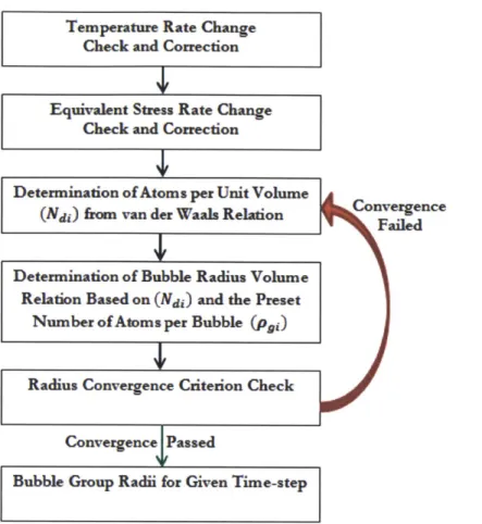
Figure 23: Bubble group radius determination algorithm for the constant atom number version of F E A ST -M E T A L ... 66
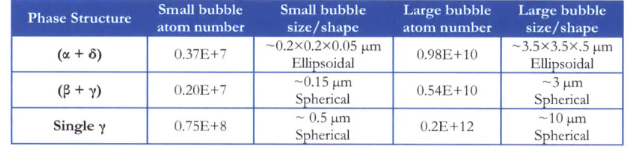
Figure 24: Bubble morphology at (a) (oc + 8) phase, (b) (P + y) phase, (c) Single y phase [10]...70
Figure 25: Probability distribution function for bubble diameter for experimental work given in [18] ... 7 4 Figure 26: Bubble separation schem e [21] ... 75
Figure 27: C rack length definition [21]... 75
Figure 28: Average distance between small bubbles...76
Figure 29: Average distance between large bubbles ... 76
Figure 30: Peak linear power for X425 benchmark [4] ... 80
Figure 31: Power peaking factor for X425 benchmark [4]...80
Figure 32: Coolant exit temperature for X425 benchmark [4]...81
Figure 33: Peak linear power for X430 benchmark [4]... 83
Figure 34: Power peaking factor for X430 benchmark [4]...83
Figure 35: Coolant outlet temperature for X430 benchmark [4]...84
Figure 36: Peak linear power for long-term case [21]...86
Figure 37: Power peaking factor for long-term case [21]...86
Figure 38: Coolant benchmark parameters for long-term case [21]...87
Figure 39: Maximum cladding strain results for the 2 group constant volume number version of FEAST-METAL for both X425 and X430 from EBR-1I [2]...89
Figure 40: Fractional fission gas release results for the 2 group constant volume number version of FEAST-METAL for both X425 and X430 from EBR-II [2]...90
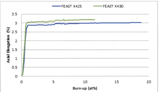
Figure 41: Fuel axial elongation release results for the 2 group constant volume number version of FEAST-METAL for both X425 and X430 from EBR-I...90
Figure 44: Fractional fission gas release results for the 3 group constant volume number version of
FEAST-METAL for both X425 and X430 from EBR-1I [2]... 93
Figure 45: Fuel axial elongation release results for the 3 group constant volume number version of
FEAST-METAL for both X425 and X430 from EBR-II...93
Figure 46: Fuel swelling results showing closed, open, solid fission products and total swelling for the 3 group constant volume number version of FEAST-METAL for case X425 at 0.37 normalized ax ial h eig h t ... 9 4
Figure 47: Maximum cladding strain results for the 4 group constant volume number version of
FEAST-METAL for both X425 and X430 from EBR-II [2]...95
Figure 48: Fractional fission gas release results for the 4 group constant volume number version of
FEAST-METAL for both X425 and X430 from EBR-I [2]...96
Figure 49: Fuel axial elongation release results for the 4 group constant volume number version of
FEAST-METAL for both X425 and X430 from EBR-II...96
Figure 50: Fuel swelling results showing closed, open, solid fission products and total swelling for the 4 group constant volume number version of FEAST-METAL for case X425 at 0.37 normalized ax ial h eig h t ... 9 7
Figure 51: Maximum cladding strain results for the constant atom number version of FEAST-METAL for both X425 and X430 from EBR-II [2]...98 Figure 52: Fractional fission gas release results for the constant atom number version of
FEAST-M ETAL for both X425 and X430 from EBR-II [2]... 99
Figure 53: Fuel axial elongation release results for the constant atom number version of FEAST-M ETAL for both X425 and X430 from EBR-II... 99
Figure 54: Fuel swelling results showing closed, open, solid fission products and total swelling for the constant atom number version of FEAST-METAL for case X425 at 0.37 normalized axial h e ig h t ... 1 0 0
Figure 55: Maximum cladding strain results for the phase dependent constant atom number version of FEAST-METAL for both X425 and X430 from EBR-II [2]... 101
Figure 56: Fractional fission gas release results for the phase dependent constant atom number version of FEAST-METAL for both X425 and X430 from EBR-II [2]... 102
Figure 57: Fuel axial elongation release results for the phase dependent constant atom number version of FEAST-METAL for both X425 and X430 from EBR-I... 102
Figure 58: Fuel swelling results showing closed, open, solid fission products and total swelling results for the phase dependent constant atom number version of FEAST-METAL for case X425 at 0.37 n o rm alized axial h eigh t ... 103
Figure 59: Maximum cladding strain results for the phase dependent constant atom number version with improved bubble distance equations of FEAST-METAL for both X425 and X430 from
EBR-1I [2] ... 1 0 4 Figure 60: Fractional fission gas release results for the phase dependent constant atom number version with improved bubble distance equations of FEAST-METAL for both X425 and X430 fro m E B R -II [2] ... 10 5
Figure 61: Fuel axial elongation results for the phase dependent constant atom number version with improved bubble distance equations of FEAST-METAL for both X425 and X430 from EBR-II 105
Figure 62: Fuel swelling results showing closed, open, solid fission products and total swelling results for the phase dependent constant atom number version with altered bubble distance equations of
FEAST-METAL for case X425 at 0.37 normalized axial height... 106
Figure 63: Anisotropy fitting factor for q/D=650 W/m for constant volume versions of FEAST-M E T A L [16] ... 10 7
Figure 64: Anisotropy fitting factor for q/D=790 W/cm2 for constant volume versions of
FEAST-M E T A L [1 6] ... 10 7
Figure 65: Anisotropy fitting factor for q/D=650 W/cm2 for constant atom number versions of
F E A ST -M E T A L ... 10 8
Figure 66: Anisotropy fitting factor for q/D=790 W/cm2 for constant atom number versions of
F E A ST -M E T A L ... 109
Figure 67: Axial cladding hoop strain profile for all versions of FEAST-METAL [2] ... 111 Figure 68: Comparison of maximum cladding hoop strain results for the sample long-term case (the 2/3/4 group designations all refer to constant volume versions of FEAST-METAL)... 114 Figure 69: Comparison of fission gas release results for the sample long-term case (the 2/3/4 group designations all refer to constant volume versions of FEAST-METAL)... 115
Figure 70: Comparison fuel axial elongation results for the sample long-term case (the 2/3/4 group designations all refer to constant volume versions of FEAST-METAL)... 116
Figure 71: Fuel swelling at 0.37 normalized axial height for the long-term case using the 2 group constant volum e version of FEA ST-M ETA L... 117
Figure 72: Fuel swelling at 0.37 normalized axial height for the long-term case using the phase dependent constant atom number version of FEAST-METAL ... 118
Figure 75: Maximum cladding strain for the sensitivity study on the high temperature diffusion constant for the phase dependent version ... 122 Figure 76: Fractional fission gas release for the sensitivity study on the high temperature diffusion constant for the phase dependent version ... 123
Figure 77: Maximum cladding strain for the sensitivity study on the low temperature diffusion constant for the phase dependent version ... 124
Figure 78: Fractional fission gas release for the sensitivity study on the low temperature diffusion constant for the phase dependent version ... 124 Figure 79: Maximum cladding strain for the sensitivity study on the open pore formation constant fo r th e 4-gro up versio n ... 126
Figure 80: Fractional fission gas release for the sensitivity study on the open pore formation
constant for the 4-group version ... 126
Figure 81: Maximum cladding strain for the sensitivity study on the open pore formation constant for the phase dependent version of the code ... 127 Figure 82: Fractional fission gas release for the sensitivity study on the open pore formation
constant for the phase dependent version of the code ... 127
Figure 83: Maximum cladding strain for the sensitivity study on the surface area correction factor for the 4- group version o f the code ... 129 Figure 84: Fractional fission gas release for the sensitivity study on the surface area correction factor for the 4- group version of the code ... 129 Figure 85: Maximum cladding strain for the sensitivity study on the surface area correction factor for the phase dependent version of the code... 130 Figure 86: Fractional fission gas release for the sensitivity study on the surface area correction factor for the phase dependent version of the code ... 130 Figure 87: Maximum cladding strain for the sensitivity study on the effective porosity correction for the phase dependent version of the code... 132
Figure 88: Fractional fission gas release for the sensitivity study on the effective porosity correction for the phase dependent version of the code ... 132
Figure 89: Cladding hoop strain for the constant volume version of FEAST-METAL at 15.8 at% burnup for 20 second tim e-steps... 135
Figure 90: Cladding hoop strain for the phase dependent version of FEAST-METAL at 15.8 at% burnup for 20 second tim e-steps... 136
Figure 91: Cladding hoop strain for 14 node FEAST-METAL and 13 node CAFE at 15.8 at% burnups with constant volume (V1) and constant atom number (V2) fission gas release models [23]
List of Tables
Table 1: Steady-state metallic fuel performance codes [4]...29
Table 2: Comparison of X425 peak clad strain for ALFUS, FEAST and LIFE [16]...38
Table 3: Radii of bubble groups used (microns) [16] ... 57
Table 4: Fitting factor in multi-group versions of FEAST-METAL [16] ... 57
Table 5: Fitting factors for 2-group constant atom number version of FEAST-METAL [16]...65
Table 6: Small and large bubble size and number of atoms per bubble ... 70
Table 7: Fitting factors for phase dependent version of the code [16]...72
Table 8: Fitting parameters used with new distance case [16]... 77
Table 9: X 425 benchm ark param eters [4]... 79
Table 10: X 430 benchm ark param eters [4]... 82
Table 11: Long-term case param eters [21] ... 85
Table 12: Fuel axial elongation results for constant volume versions of FEAST-METAL ... 108
Table 13: Fuel axial elongation results for constant atom number versions of FEAST-METAL ... 109
Table 14: Summary of fraction fission gas release results for developed benchmarks [2]... 110
Table 15: Cladding hoop strain results for constant volume versions of the FEAST-METAL [2]. 110 Table 16: Cladding hoop strain results for constant atom number versions of the FEAST-METAL [2]... 1 10 Table 17: D iffusion constant sensitivity studies ... 120
Table 18: Open pore formation constant sensitivity studies... 125
Table 19: Surface area correction factor sensitivity studies ... 128
Table 20: Effective porosity correction sensitivity study ... 131
Table 21: Time-step stability analysis of three versions of FEAST-METAL using 7 axial nodes (running to completion is denoted by a "Y", otherwise code failure mechanism is noted)... 133
Table 22: Time-step stability analysis of three versions of FEAST-METAL using 14 axial nodes (running to completion is denoted by a "Y", otherwise code failure mechanism is noted)... 133
Table 23: Time-step stability analysis of three versions of FEAST-METAL using 20 axial nodes (running to completion is denoted by a "Y", otherwise code failure mechanism is noted)... 134
Table 24: Cladding strain (in terms of percentage -%) at 18.9 at% burnup for the X425 assembly from EBR-II with varying time-steps and number of axial nodes ... 134 Table 25: Fraction fission gas release (in terms of percentage -%) at 18.9 at% burnup for the X425
1. Introduction
Fast reactors in both the United States and in Europe developed two main types of fuel that were extensively tested. The first type of fuel is mixed oxide (MOX) using oxides of uranium, plutonium and other actinides. The second type of fuel is metallic fuel, which primarily consists of uranium, zirconium and plutonium. Both of these types of fuels have been extensively tested in reactors both in the United States and in Europe. The EBR-II in the United States, Phenix and Superphenix in France and the BN-600 in Russia all proved the viability of fast reactor technology based on these
fuel types for the generation of large amounts of electricity. Carbide and nitride fuels, while tested, have not been as extensively characterized because of the success of oxide and metallic fuel in the
1980s and 1990s. More recently, the push towards the creation of new Generation IV reactors has renewed interest in the development of liquid metal fast reactors. New reactor concepts proposing ultra-high burnups (-35 at%) and extended cycle lengths (-40 years) are currently being developed. One such example is the Travelling Wave Reactor proposed by TerraPower. [1] These reactors are all Liquid Metal Fast Reactors (LMFR) and are sodium cooled.
One of the main constraints in the development and deployment of this type of reactor is the fuel itself. Due to the fast flux environment and the use of sodium as a coolant, the degradation and
failure of materials and fuel is the limiting factor to increasing burnup. Because of the large difference in the environment of a fast reactor in comparison to a light water reactor (LWR), the tools developed for the materials and fuel analyses of LWR systems were not viable for use in fast reactors. Because of this, an entirely different set of codes was needed. This necessity led to the development a large number of fuel performance codes for both oxide and metallic fuels. Due to the large difference in behavior between the ceramic oxide fuel and the oxide fuel, one code cannot model both oxide and metallic fuel without separate modules.
This thesis focuses on the improvement of the fuel performance code FEAST-METAL, which was developed to simulate the performance of metallic fuel and its cladding in a liquid sodium
environment. In particular, the fission gas and swelling modules of FEAST-METAL are examined. In this section, background information necessary to understanding metallic fuel and fast reactors will be presented. Its physical behavior under irradiation and modeling tools developed to predict its behavior are addressed accordingly.
1.1. Metallic Fast Reactor Fuel Overview
Metallic fuel as we know it is composed of uranium, plutonium and zirconium. A cylindrical slug made up of a composite of these three elements is encased in stainless steel cladding. The gap between the fuel and the clad is filled with sodium which increases conductance between the clad and the fuel, reducing peaking. See Figure 1. This section discusses the development of this fuel and some of the physical phenomena that occur when it is irradiated. Particularly it covers fuel swelling, constituent redistribution, phase structure and morphology, fission gas release, fuel clad chemical interaction and fuel clad mechanical interaction.
Clwdding
Plenum -ir
Sodium
Fuel Slug
Top End Plug Bottom End Plug
Figure 1: Typical metallic fuel pin from EBR-II, showing key features. [2]
In comparison to oxide fuels and other ceramics, metallic fuel carries a number of advantages. High thermal conductivity in the fuel leads the system to have a passively safe response to anticipated-transient-without-scram initiators in metallic-cooled fast pool reactors. High thermal conductivity also leads the fuel to have a lower peaking factor; thus allowing a higher linear pin power. Also, experimental testing has shown that the fuel can reach near 20 at% burn-up without failure. [3] The heavy metal density and low moderating power provide a harder spectrum, allowing better neutron economy than oxide fuels. [4]
operation, the core can still be run without further degradation at the location of the breach. Tests in EBR-II demonstrated the ability for fuel to be irradiated up to 200 days after failure [5] The
inclusion of zirconium in the fuel prevents a large release of iodine, which is a one of the most common fission products. While reprocessing the fuel is relatively simple, the fission products can never be fully separated from the fuel, reducing the possibility of using plutonium and other actinides for weapons.
Current metallic fast reactor fuel is initially a homogenous mixture of U-Pu-Zr in varying weight percent. Plutonium concentration varies from 0-19 wt%, while zirconium concentration is typically
6-10 wt/o. In EBR-II, uranium enrichment was high and ranged from 60 to 90 wt% and over. [6]
These percentages depend primarily on whether the fuel is part of the blanket or initial central core (driver fuel). The fuel cannot simply contain uranium and plutonium because the melting point of the solution is too low. Zirconium is a good added material because it both reduces the effect of fuel-clad-chemical interactions and raises the solidus. The concentration of zirconium is limited to roughly 10% because the fuel can no longer be cast into molds if it is present in a higher weight fraction. [5] To form the fuel, it is heated up and cast into quartz molds. [7] The smear density of the fuel is usually between 60% and 75%. [6] The rest of the clad interior has a sodium bond.
Additionally, the fuel pin must have a large plenum to accommodate the large amount of fission gas that is released from the fuel matrix. See Figure 2. The low smear density is necessary because of the large amount of volumetric swelling the metallic fuel undergoes. The cladding is ferritic stainless steel, usually HT-9. Other steels were tested in the past, notably 316, D9 and 304, but their swelling rate was too high for them to be viable at higher burnups. [5]
o
.
I I
I I
I-
J
11
1
I
I
I I
I
I-I
7 - K--l 09, 20 X CW 44 -304L. SA bx 6-5 - MK--I 316, SA 4n.. 304L, SA 3- 2-HT9, 20 X CW 0 2 4 6 8 10 12 14 16 18 20PEAK 8URHP (ot. X)
1.1.1. Constituent Redistribution
Initially the fuel is a near homogenous solution of U-Pu-Zr in their initial concentrations. However, after irradiation begins, the thermal gradient created within the fuel causes the different phases in the fuel to form, corresponding to different regions of the ternary phase field. These different phases have different concentrations of zirconium and uranium. These different phases ultimately lead to the diffusion of zirconium and uranium into and out of specific radial regions of the fuel. Thermo-transport may also be a contributing factor to this redistribution. [8] Modeling this phenomenon is important because each of the fuel regions has its own unique characteristics. Figure 3 shows the formation of three distinct regions within the fuel. The center and outer regions have become enriched with zirconium, while the middle region is depleted. The uranium conversely has a higher concentration in the middle region and is depleted in the center and outer regions. The plutonium concentration shows a slight gradient from the center to the fuel exterior. [9]
0.5 mm
Figure 3: Axial cross section of the fuel with an overlay showing the radial distribution of the elements present for a U-19Pu-lOZr fuel pin from EBR-II at 1.9 at% burnup. [9]
1.1.2. Fuel Phase Structure and Morphology
Because the fuel is a ternary alloy consisting of U-xPu-yZr or a binary alloy of U-yZr, the phase structure of a fuel slug can become very complex when the temperature gradient and subsequent constituent redistribution is taken into account. The ternary alloy phase diagram can be seen in Figure 4, while the binary alloy phase diagram can be seen in Figure 5.
U U 20 Y+O 20 20 20
/
Y++ YY k.5 sos o so 2r+ + 10 Y+O
4~'r z 0 4 s o 20 40 Zo s o r (a) (b) 60 ;+ 440o1 80 60 C 0 C0Fir 4:LI Tear paedarmfoth -uZsytmshwnthpaesftefel.aQ 70C
Zirconium,
0/o
800 c 600 -750 0.21 .65 2 L.07 Z.0 SZrconium, wt Y a + S (See Insert) 650 1E a)r2+ 1617*C 600 a + 550 5 10 15 20 25 Zirconium, w/oFigure 5: Binary uranium-zirconium phase diagram [10]
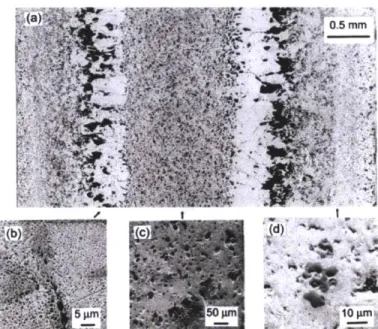
In a ternary alloy, three main regions form. Figure 3, Figure 6 and Figure 7 all show this three-region nature in different ways. Figure 3 in the preceding sub-section shows the axial cross section; Figure 7 shows a radial cross section; Figure 6 shows a calculated radial temperature distribution. All are of a U-19Pu-1OZr fuel pin. [9]In fuel with this make-up, the central region become y phase, the outer region becomes 8 + ( and the intermediate region becomes y + (. [9]Each of these different regions has a distinct morphology and behaves differently under irradiation. Figure 7 shows the morphology of each of these different regions. The issue is further complicated when the diffusion of gas atoms through this three-region fuel slug, and the constituent redistribution of uranium and zirconium is taken into account. Each of these three regions has a different amount of porosity created by fission gas, a different thermal conductivity and different mechanical properties.
700 680- 7 7( +
~640.
620. 600-*580 560 540 520 0.0 0.2 0.4 0.6 0.8 1.0Relative radius from center (r/R)
Figure 6: Calculated temperature distribution of EBR-II pin T-179 at axial location x/L=0.67 from the bottom showing phase fields. The dashed line is the beginning of life temperature and the solid
line is the temperature distribution later in life. [9]
Sp 0 M
Figure 7: Pore morphology of U-Pu-Zr fuel shown by SEM and optical metallography: (a) optical micrograph of axial cross section, SEM image of, (b) intermediate zone, (c) central zone, (d) outer
zone. [9]
outer a + 8 and the intermediate a + y. If the temperature is high enough, then a y-only region can also form. [10]
1.1.3. Fuel Swelling
Swelling in metallic fuel is primarily a result of fission gas release, irradiation growth, grain boundary mechanical cavitation and solid fission product accumulation. [10] Fission gas release and grain boundary cavitation cause both open and closed porosities. Solid fission product formation is linearly dependent on burnup, since it is dependent on the fluence. Due to the different phases present in the fuel, swelling is highly anisotropic.
Anisotropic irradiation growth of single crystals occurs in orthorhombic alpha uranium, which primarily forms between 400 C and 650 C. In this phase {010} elongation and {100} shrinkage occur simultaneously due to the anisotropic condensation of interstitial and vacancy loops. [10] This anisotropic growth causes mismatched stresses and results in cavities forming in the fuel. [10]Here the zirconium can form the hexagonal delta phase (UZr2), the tetragonal zeta phase, or precipitates stabilized by oxygen, carbon or nitrogen. [10] Though these cavitation voids are partially filled with lanthanide-rich fission products, these tears are relatively compressible, unless filled by fission gas due to migration at higher burnup. [5] [10]
Fission gas, particularly Kr and Xe, nucleates into bubbles which migrate to phase boundaries; eventually they migrate from there to the fuel surface, where the contents of the bubble are released to the plenum. [10] When the gas bubbles are contained within the matrix of the fuel, they are considered closed porosity. When they are connected to the plenum, they are considered open porosity. Open porosity begins at roughly 0.5 at% burnup, which corresponds to ~10% volumetric swelling. This is an experimental data point. Metallic fuel codes use one of the two previous conditions to trigger the release of fission gas from the fuel matrix.
Solid fission products accumulate linearly with burnup, since their rate of production is dependent on the fluence. They account for roughly 1.2% volumetric swelling per atom percent burnup. [5]
While this is not a limiting condition at burnups less than 20 at%, it can become a primary failure mechanism if burnup is increased to 30 at% or higher. The primary solid fission products are Mo, Ru, Pd and the lanthanide series. [10]
Fuel swelling occurs rapidly after irradiation starts and does not see a decrease in rate until the fuel becomes radially restrained by the clad. The fuel becomes radially restrained at roughly 2 at% burnup which corresponds to 15 to 25 at% burnup. [10] At this point the swelling rate decreases because of the pressure exerted on the fuel by the cladding. The cladding is not breached because, at this point, the fuel contains a large amount of open porosity, which becomes sintered as the pressure on the fuel increases. The average radial swelling (Ad/do) was greater than the axial swelling (Al/
I
0) of the fuel by a factor 2 to three. This is thought to be a result of the manufacture process and the directional solidification of the alloy in its quartz mold. [10] Axial fuel swelling can be found experimentally, while radial fuel growth is not directly found because of the difficulties in making a measurement. Axial growth also has a large dependence upon the concentration of plutonium in the fuel; larger concentrations of plutonium lead to smaller axial fuel growth, which corresponds to a larger degree of fuel anisotropy deformation. [10]OU IOZa Ou-8PU IOZR X[J 19pu-1OZR
121
80
w
o5 4
1.1.4. Fission Gas
Because fission gas is the primary cause of pin swelling and thus cladding strain, understanding the mechanisms of fission gas release and retention is of utmost importance. This thesis, in fact, focuses on new ways to model this phenomenon in the code FEAST-METAL. Based upon experimental results, some conclusions can be made about the behavior of the fission gas. The quantity of gas which percolates into the pin plenum shows a nearly linear dependence on burn-up, once an initial gas formation period of about 0.5 at% has passed. [11]
OcORFELAION 9%RELU-IOZR +%R8ELU-PU 10ZR 3% AEL U-19PU-102R 100 90 8o 70 0 4 8 1O 12 14 1 % BURNUP
Figure 9: Fractional fission gas release behavior in U-xPu-10Zr metallic fuel [11]
Figure 9 shows that fractional gas release (the percentage of gas that is created that is released from the fuel matrix to the plenum) increases rapidly and asymptotically reaches a maximum of 60% to
80% depending on the fuel initial composition and irradiation history. Finally experimental studies
show that there is little axial variation in the rate of fission gas release, indicating that temperature and diffusion distance to the plenum are not driving forces. [11] Open porosity is attained at a low burnup, which is apparent in Figure 9. Fission gas cannot be released unless there are open pores in the fuel. This means fission gas release occurs at all relevant temperatures. Figure 10 shows the total amount of gas released as a function of burnup.
6500 6000 5500 3000 4500 4000 3500 3000 2500 2000 1500 1000. 0 0 2 4 6 8 10 12 14 % BURNUP
Figure 10: Total amount of fission gas released as a function of burnup for U-xPu-lOZr fuels (includes 0, 8 and 19 wt% Pu) [11]
1.1.5. Fuel Clad Mechanical Interaction (FCMI)
The creation of solid fission products and fission gas within the fuel matrix causes the fuel to swell until it reaches the cladding. When it is there it will exert pressure upon the cladding, resulting in creep and possibly causing failure. This was a limiting factor in the design of early metallic fuel, which had a higher smear density. Original smear density was ~85%; current fuel has a smear
density of ~75%. [7] When the fuel touches the clad, the porosity of the fuel becomes compressed, but the fuel can only be compressed up to a certain point and eventually failure occurs due to the pressure exerted by the formation of solid fission products. At low smear densities, only when a low-swelling cladding material such as HT-9 is used does FCMI become an issue. The hoop strain of
D9, 316 and 304 stainless steels seen in Figure 2 can all be accounted for by cladding creep due to
1.1.6. Fuel Clad Chemical Interaction (FCCI)
Since both the fuel slug and its stainless steel cladding are both alloyed metals, the problem of interdiffusion between constituents of the cladding and fuel and fission products can be a limiting factor. Diffusion between the clad and the fuel can result in structural weakening of the clad and the formation of low melting point compositions in the fuel. [5] Fe and Ni diffuse into the fuel, while lanthanide fission products diffuse into the clad. Lowering the melting point of the fuel limits the transient performance and off-normal capabilities of the fuel pin. Penetration of lanthanides leads to the formation of an interaction layer that grows with burnup. This region is harder and more brittle than the rest of the clad and limits steady state performance. [11] The resultant interaction layer can be seen in Figure 11.
100 microns
Figure 11: SEM of the interaction between D9 cladding and U-Pu-Zr fuel at -12 at% burnup showing the increased hardness of the interaction region [11]
1.2. Metallic-Fueled Fast Reactors
This section provides an overview on the operational history of EBR-II and a synopsis of the Travelling Wave Reactor concept developed by TerraPower. Both of these reactors utilize ternary U-Pu-Zr fuel. Additionally, the EBR-II fuel experience is used to benchmark the FEAST-METAL code. Fuel irradiations similar to those used in the Travelling Wave Reactor are also examined for long-term cases. The Phenix, Superphenix and BN-600 reactors are not discussed in depth since
they did not use metallic fuel and are therefore provide neither benchmark nor test cases for this thesis.
1.2.1. EBR-1I
The Experimental Breeder Reactor-II (EBR-II) operated at 62.5 MWth and 20 MW; it was a pool type reactor cooled with sodium. It operated for 30 years, going critical in 1964. The reactor itself was immersed in a 90,000 gallon pool of molten sodium. The core was surrounded by both axial and radial uranium blankets which were used to generate (breed) plutonium. The reactor ran on both metallic and oxide fuel pins. [7]
Early in the life of the reactor, the burnup of fuel pins were severely limited by material, fuel design and hexagonal ducts which contained the fuel. Stainless steel, that was originally used as cladding, had a much higher swelling rate than the HT-9, that was used later in life. Early fuel designs had a much higher smear density than 75%. Initially the smear density ranged from 85% to 100%. This high smear density did not accommodate the large amount of fission gas swelling that occurs in metallic fuel, leading to fuel pin failure at low burnup. The stainless hexagonal ducts that contained fuel pins underwent significant deformation due to swelling as a result of irradiation. These material
15 10 Mark-Il Mark-IA 0 k it a . . . . . . . . . 1964 1968 1972 1976 1980 1984 1988
DATE BURNUP LIMIT ACHIEVED
Figure 12: Burnup limit for different generations EBR-II driver fuel [7] The initial fuel used in the reactor was a combination of uranium and fisium (Fs), which is an equilibrium concentration of fission product elements left by the pyro-metalurgical reprocessing cycle. [7] Mark-IA fuel had U-5Fs fuel and was clad in austenitic stainless steel. [7] Mark II fuel also used U-5Fs fuel but was clad in 304 stainless steel; later in 316 stainless steel was also used as cladding. [7] Eventually this fuel evolved into the ternary U-Pu-Zr fuel described in the previous section. The fuel itself was formed by injection casting into quartz molds, a process which can be seen in Figure 13. [7] Mark IIA fuel used ternary fuel and was clad in ferritic stainless steel (D9 or HT9).
Figure 13: EBR-II fuel pins being fabricated by injection casting. [7]
In order to determine which specific fuel pin failed, each pin had a unique mixture of xenon in the plenum. When a pin failed, the gas would escape and be detected by a mass spectrometer, leading to easy identification. This allowed the exact time of cladding failure to be determined. The highest burnups for the EBR-II, roughly 20 at%, were achieved for low smear density fuel clad in HT-9.
Cases from EBR-I were used to benchmark the FEAST-METAL codes developed in this thesis. More information on the irradiation history of those pins is included in the section of this report which details the benchmarks performed. [7]
1.2.2. Travelling Wave Reactor
The Travelling Wave Reactor (TWR) is a reactor currently being engineered by TerraPower LLC. It aims to offer significant advantages over both LWRs and traditional fast reactor technologies. Namely, it aims at being fueled with internally generated fissile material for most of its life. Like many other fast reactor designs, this reactor makes use of blanket and driver regions. The central region is at a much higher power initially due to its fuel with higher enriched heavy metal. The fast fission neutrons are absorbed in the blanket region, resulting in fertile isotopes there becoming fissile. When the central region of the core begins to lose reactivity, the newly made fissile isotopes are moved from the outer blanket region to the central region. Figure 14 shows this core schematic.
criticality to near 15 at% burnup, while later generations could remain critical to over 40 at% burnup. However, with so high a desired burnup, the radiation resistance requirements placed on
the materials in the reactor become much greater. FEAST-METAL and other metallic fast reactor fuel codes are currently being used to evaluate the performance of TWR fuel under the conditions proposed by TerraPower. [1]
1.3. Fuel Performance Code Evolution
In order to predict the behavior of metallic fuel beyond current experimental data and to interpolate between existing points, fuel codes were developed to model the behavior of metallic fuel. This modeling especially becomes an issue when predicting behavior of the fuel well beyond the current data. The highest burnup data points correspond to 20 at% burnup, while for the proposed fuels it is desired to extend burnup to over 30 at%. Because the predictions are entirely dependent on the models used in the code, the development of codes based on physical principles is of the utmost importance. Experimental correlations cannot be used to extrapolate fuel behavior to 50% beyond the highest burnup data point. Because of this, metallic fuel codes have moved away from empirical correlations to physics-based models. Although, without experimental proof, these models cannot be verified; they are an improvement over a purely extrapolated and empirical approximation. This thesis focused on improving the fission gas and swelling module of the code FEAST-METAL. In order to better understand previous models that were created and used, a literature review of fission gas modules of each of these codes was conducted. In addition, the general capabilities of each of the relevant Metallic fuel codes were reviewed and discussed in this section. Table 1, which is taken from Karahan's thesis, covers the basic models present in relevant codes and their capabilities.
Table 1: Steady-state metallic fuel performance codes [4]
Modules IFE-METAL SESAME ALFUS MACSIS FEAST-METAL
Developer ANL (US) CRIEPI CRIEPI KAERI MIT (US)
_JAPAN) (JAPAN) (re)
General Capabilities Steady-state and Steady-state Steady-state Steady-state Steady-state and Transient Behavior Behavior Behavior Behavior Transient Behavior Fission Gas Release Empirical Empirical Mechanistic Mechanistic Mechanistic and Fuel Swelling Correlation Correlation Model, based Model, Model, Based on
on Uo2 Fuel Based on Metallic Fuel
UO 2 Fuel
Constituent Empirical Chemical Thermo- Thermo- Thermo-transport
Redistn'bution Corelation Equilibrium transport transport theory
Model eory _ __y
Temperature 1D Model ID Model ID Model 1D Model 1D Model
Distribution
Mechanical 1D Model ID Model 2D Model ID Model 1D Model
Analysis
FCCI Empirical Not Included Empirical Not Diffusion Model
Correlation Correlation Included based on
Precipitation Kinetics
Creep Fracture Cumulative N/A N/A N/A (1) Cumulative
Damage Fraction Damage Fraction
Model Model
(2) Constrained Diffusional Cavity Growth Model
The most important physical phenomena that need to be modeled are discussed in detail in the Metallic Fast Reactor Fuel Overview section of this thesis. They include fission gas release, swelling, anisotropic fuel deformation, temperature, FCCI, mechanical behavior, creep fracture, constituent redistribution and phase structure. This section focuses on the five codes in the above table and the
GRSIS and OGRES algorithms, which are used in some of these codes. Special emphasis is taken to
describe the fission gas and swelling modules of each of the codes since these phenomena are the main focus of this thesis. This is done to show the wide range of current models.
1.3.1. LIFE-METAL
LIFE-METAL is an adaptation of the oxide code LIFE. It includes thermo-mechanical analyses of the fuel and cladding in the radial direction. The code can accommodate axial variation through different fast flux and specific power inputs. Fuel temperatures are based on calculated coolant temperatures at the given axial height. There is no axial coupling for either mechanical processes or temperatures. The code calculates fuel swelling and fission gas release based upon empirical
correlations which use temperature, porosity and burnup as independent variables. Since porosity can be seen as a function of burnup and temperature, these are the two main driving variables for fission gas release and swelling determination. The swelling and fission gas release correlations are very similar to the SESAME models without a maximum bubble concentration correction. {See Equations 2 and 3} The code models both steady-state and transient behavior. For FCCI and constituent redistribution, empirical correlations based on EBR-II data are used. Overall, the code uses a 1D model for temperature and mechanical analyses. [4] [12]
1.3.2. SESAME
Since the code LIFE-METAL was not well developed in comparison to the mixed oxide fuel performance codes, the Central Research Institute of the Electric Power Industry in Japan developed their own code to model metallic fuel in a liquid metal environment. This code,
SESAME, predicts steady-state irradiation performance of metallic fuels through the use of simple
empirical correlations. The code uses a finite element method (FEM) with one degree of freedom for both the fuel temperature and stress-strain calculations. The fission gas release model is based on those employed in LIFE-METAL and are based on empirical relations dependent on burn-up and other fuel parameters. [12]
Nr
= Fg -Gs Eqn. 1F9 = [1 - exp(-a - Bu)] 1 + Cg(P-. 01)P3 R9 x exp (- +
f
- (s - Eg) Eqn. 2dr:
Fission product gas release rate (mol/sm3G,: Retained fission product gas (mol/m)
Bu: Burnup (at%)
P: Porosity
Es: Gas swelling (volumetric change)
T: Temperature (K)
a,
Cg, E;: Dimensionless fitting parametersRg, ,
f:
Dimensional fitting parametersLike the fission gas release model, the fuel swelling model is also based on the LIFE-METAL code. Gas bubble radius is found by applying the equilibrium condition between internal gas pressure and external pressure plus surface tension. To find the concentration of fission gas atoms, the following relation is used. The minimum function is applied to better model the bottom of fuel pins, which was predicted incorrectly by LIFE-METAL. [12]
Cb = min Bb exp
()
,Cmax Eqn. 3Cb: Fission product gas bubble density (#/m 3)
Cmax: Maximum allowed concentration (#/m 3) Bb: Dimensionless parameter
The code also models constituent redistribution and sodium bond infiltration into the fuel, which results from the fuel's high porosity. Finally, there are corrections to take into account the
anisotropic deformation of the fuel. While the code is valid for examining the fuel from EBR-II, the fact that there are very few degrees of freedom in the empirical correlation developed, leads to questions about the code's ability to accurately model metallic fuel which has irradiation histories different from the types found in EBR-II. [12]
1.3.3. OGRES
The first use of multiple bubble groups in modeling the creation and release of fission gas in metallic fuel was performed in the OGRES code, which models fission gas swelling and release for ternary metallic fuel under steady-state conditions. The model was originally created for oxide fuel and then adapted to ternary metallic fuel. This model assumes that gas atoms that are generated in the fuel either precipitate together to form bubbles or remain dispersed within the fuel matrix. Both these atoms and bubbles then diffuse through the fuel matrix, eventually reaching the grain boundaries of the alloy. Bubble number density is determined by the same equilibrium analysis that SESAME uses. This model uses six different bubble group classifications. Five of the bubble groups represent closed bubbles, while one represents open ones. The probability that any gas is released is a function of local swelling. This code only models the formation of fission gas bubbles, related gas release and swelling. It does not couple these phenomena with mechanical, chemical or thermal properties. [13]
Generation
In-grain Subble Model
Single Gas Atom be-solution
In-9ta).n DubbLo
F7
(Claus
0) Precipitation and/orF 1% tapping Supply (diffusion) CIA** I-TM Coa2e.uaceo-ewdn up Class 2 class 3 Class areas
Grain-boundary Bubble modal
Figure 15: ORGRES fission gas behavior algorithm [13]
Fission product gas atom concentration can be explained by the following equation for in-grain bubbles. [13]
OCt = I ±(Dr 2acg) + (Dgr2 cgb + K Eqn. 4
Ct = C9 + Cgb Eqn. 5
Ct: Total fission gas concentration (#/m3)
Cg: Concentration of gas atoms dissolved in the fuel matrix (#/m 3)
Cgb: Concentration of gas included in the in-grain bubbles (#/m 3) Dg: Diffusion coefficient of a single gas atom (m2
/s)
Dub: Diffusion coefficient of in-grain bubbles (m2
/s) K9: Generation rate of FP atoms (1 /m3s)
Evaluated at steady state, this yields the rate of gas transfer from bubbles inside the fuel grain to the grain boundary. The concentration of bubbles within the grains can be found using the following relation for bubble types 1 to 5, which are all closed. Each closed bubble type has a constant number of atoms, resulting in a varying radius. [13]
- = G, + ;R - -
E
ij ; i = 1 to 5 Eqn. 6Ci: Number density of bubble type-i (#/M3
)
Gi: Increase in the number density of the type-i bubbles due to FP gas transfer from the grain (#/m3
s)
R_ Shifting rate of smaller bubbles to type-i bubble due to coalescence with type-j
(#/m3s)
R,: Shifting rate of type-i bubble to large bubbles (#/m3s)
Ri,: Collision rate of type-i bubbles with type-j bubbles, and hence the coalescence of the bubbles (#/m3s)
The collision rates and shifting rates depend on the bubble class; however, they are all similar in form. [13]
r.: Radius of bubble type-i (m)
M: Mass correction or probability correction depending upon the bubble group
Open bubbles use a different concentration equation because they cannot collide with other bubbles because they are immobile, which is part of the definition of open porosity used in fuel codes. The variables here are the same as above with different indices. [13]
dR = R - = Eqn. 8
Based on this concentration, the rate of change of swelling is calculated as a function of both open and closed bubbles.
1.3.4. ALFUS
The ALFUS code (ALoyed Fuel Unified Simulator) mechanistically predicts the fission gas release rate and the deformation behavior of ternary U-Pu-Zr fuel. Unlike other metallic fuel performance codes, it incorporates a 2D mechanical analysis model; its temperature model is still 1D though. This code is also the first code to use a mechanistic model to predict the behavior of fission gas and related swelling. This aids in the determination of the fission gas release rate, the amount of
anisotropic fuel deformation and the analysis of the FCMI. This code also mechanistically takes into account constituent redistribution, but it does not couple this to the mechanical model. The ALFUS fission gas model is based on the OGRES fission gas release model. The size of the grain-boundary bubbles used in the OGRES algorithm is fixed based upon a constant number of atoms.
Accordingly, the radii vary. In comparison of the FEAST-METAL and the GRSIS algorithm it uses, there are a few differences. In-grain bubbles are treated explicitly by the ALFUS, while they are not done so in FEAST-METAL. Additionally probabilities of coalescence and diffusion rates of bubbles through the fuel are treated differently. The FCCI model is based on an empirical correlation. [14]
1.3.5. MACSIS
The MACSIS code is a steady-state which models temperature and fuel mechanics in 1D. Like other models, it uses thermo-transport theory for constituent redistribution and a mechanistic model based on U0 2 fuel to predict fission gas release and swelling. There is no FCCI or creep fracture
module within the code. The fission gas release model involves two separate models for intra-granular and inter-intra-granular fission gas release. The intra-intra-granular model is based on Booth's classical diffusion theory. This model treats the release of fission gas from the fuel matrix as diffusion to the surface of a spherical grain. Gas is created uniformly with a radius of "a" at a rate of f. This leads to the following diffusion equation, which must be satisfied at all points. [15]
-=DV2C+p whereO r 5a,t=Oandc=Oatr=a,t O Eqn. 9
at
/#: Gas atom generation rate (#/m 3s)
C: Concentration of gas atoms (#/m3)
D: Diffusion coefficient (m2/s)
a: Grain radius (m)
t: Time (s)
The quantity of gas released after a time "t" is found by integrating the divergent flux across the specimen boundary up to the time "t". This result is then fed into the inter-granular model, like the OGRES and GRSIS algorithms, which uses a multi-bubble group approach. Here multi-bubble size distribution on the grain boundary and the number of bubbles per unit volume at a specified bubble-i size 0 r a, t = 0 is estimated based on the following equation. [15]
ff.i n, F(mTn)dn = f,(n+- n) Eqn. 10
T: Reduced time as a dimensionless constant
m = mgb The number of gas atoms per unit volume at the grain boundary surface
Et
mgb: Number of gas atoms per unit area on the grain boundary Et: The effective thickness of grain boundary
A, B: Dimensionless constants
The desired result here is the number of gas atoms per unit area on the grain boundary or mgb. This can be found using fi. [15]
mgb = CsZsizeranget nu +ni Eqn. 12
CS: Correlation coefficient for concentration per unit area of grain boundary
This can be rewritten to solve for Cs. Based on these equations, the number of bubbles in a given bubble size group is found to be: [15]
fi
= f, - CS Eqn. 13From here a portion of the gas bubbles connect with one another and form larger bubbles. This continues until a saturation condition is reached and then the contents of the bubbles are released to the plenum. In the model, the point when bubble interconnection first begins is described in the following equation. [15]
/ 2 rr2
rSI 2b n Eqn. 14
\Rsb crit (2rsb)2 4
rsb: Radius of a gas bubble (m)
Rsb: Radius of a circular unit cell of the grain boundary (specified parameter), (m)
From here the saturation condition at which gas release begins for a given location is described in the following manner. [15]
1 r s Eqn. 15
For the purposes of gas swelling, the volume of a bubble is determined according to the van der Waals equation based on the number of gas atoms in the bubble. With these radii, the total swelling is calculated with the following equation. This is then used to determine diametrical fuel and clad change. Since the code uses 10 separate annuli, it is summed over all of these; it is also summed over all bubble groups. [15]
S=
E
3=ti+
fS
Eqn. 16nij: Number of bubbles of size-i at annulus-j
A
V': Total volumetric change due to fuel swellingrij: Radius of bubble-i at annulus-j (m)
Vi: Volume of annulus-j
1.3.6. GRSIS and FEAST-METAL
In comparison to previous codes, the FEAST-METAL code relies less on outright empirical
correlations. However, fitting factors are still required to make the models valid. The code is capable of both transient and steady-state analysis. The fission gas model is based on the GRSIS algorithm. The GRSIS algorithm models the creation and diffusion of fission gas within a metallic fuel matrix. In logic, it is similar to the OGRES algorithm; however, there are significant differences in the treatment of in-grain bubbles, coalescence probabilities and diffusion properties. FCCI uses a diffusion model. A full analysis of relevant models in the FEAST-METAL code and the GRSIS algorithm is contained in the next chapter. Table 2 provides a comparison of the results (for clad strain at a given burnup) from the initial version of FEAST-METAL with ALFUS and LIFE-METAL. [4]
Tahlp 7. I'nn nrienn nfYA2 nY le clari etrain fnr AT FTT T FPPASrT aind T .TRP F161
Clad Strain (%)
![Figure 1: Typical metallic fuel pin from EBR-II, showing key features. [2]](https://thumb-eu.123doks.com/thumbv2/123doknet/14733615.573612/13.918.185.763.407.635/figure-typical-metallic-fuel-pin-ebr-showing-features.webp)
![Figure 9: Fractional fission gas release behavior in U-xPu-10Zr metallic fuel [11]](https://thumb-eu.123doks.com/thumbv2/123doknet/14733615.573612/22.918.227.650.377.688/figure-fractional-fission-gas-release-behavior-metallic-fuel.webp)
![Figure 10: Total amount of fission gas released as a function of burnup for U-xPu-lOZr fuels (includes 0, 8 and 19 wt% Pu) [11]](https://thumb-eu.123doks.com/thumbv2/123doknet/14733615.573612/23.918.267.658.125.437/figure-total-fission-released-function-burnup-fuels-includes.webp)
![Figure 20: Anisotropy factor for FEAST-METAL v. 1, showing two different power densities (q/D is expressed in terms of W/cm 2 ) [16]](https://thumb-eu.123doks.com/thumbv2/123doknet/14733615.573612/55.918.276.751.223.492/figure-anisotropy-factor-feast-showing-different-densities-expressed.webp)
![Figure 25: Probability distribution function for bubble diameter for experimental work given in [18]](https://thumb-eu.123doks.com/thumbv2/123doknet/14733615.573612/74.918.213.689.352.631/figure-probability-distribution-function-bubble-diameter-experimental-given.webp)
![Figure 44: Fractional fission gas release results for the 3 group constant volume number version of FEAST-METAL for both X425 and X430 from EBR-II [2]](https://thumb-eu.123doks.com/thumbv2/123doknet/14733615.573612/93.918.212.718.121.424/figure-fractional-fission-release-results-constant-volume-version.webp)