DEVELOPMENT OF A COMPUTER SYSTEM FOR 3-DIMENSIONAL SPACE ALLOCATION
IN THE EARLY STAGES OF ARCHITECTURAL DESIGN
by
Masanori Nagashima
B.S., THE UNIVERSITY OF TOKYO 1972
M. Arch., THE UNIVERSITY OF TOKYO 1974
SUBMITTED IN PARTIAL FULFILLMENT OF THE REQUIREMENTS FOR THE DEGREE OF
MASTER OF ARCHITECTURE IN ADVANCED STUDIES at the MASSACHUSETTS Signature of Author Certified by Nicholas Associate Professor, Accepted by . ... INSTITUTE OF TECHNOLOGY June, 1976 .. g 0 96 f $...* Department of Architecture May, 7, 1976 S... .Oe. . .
P. Negroponte, Thesis Advi Depart ent of rchitecture,
\
//
/A
so r, MIT
... Sm ~ .... &... . ...
Chairman, Departmental Committee
DEVELOPMENT OF A
FOR 3-DIMENSIONAL IN THE EARLY STAGES OF
COMPUTER SYSTEM SPACE ALLOCATION ARCHITECTURAL DESIGN by Masanori Nagashima Submitted to partial fulfi Architecture
the Department of Architecture on llment of the requirement of the in Advanced Studies.
May 7, 1976 in Degree of Master of
ABSTRACT
This report documents a computer system designed for three dimensional space allocation during the early stages of
architectural design. The system is called Multilevel Allocation Scheme - MAS - and is Installed on the MAGIC system at the
Architecture Machine Group in MIT's Department of Architecture. MAS uses
to investigate arrangement in
interactive calligraphic, refresh display one way to deal with architectural space
three dimensions.
technology
The basic algorithms for space arrangement have been adopted from the earlier IMAGE system. However these have been modified for application to three dimensional problems. MAS is designed to assist the user to cope with multiple-constrained problems. The essence which distinguishes MAS from other systems is its
capability to deal with three dimensional objects and its
implementation on a minicomputer. Two display screens have been used and perspective with hidden-line elimination routines has been Implemented, both to assist in visualization.
This report includes one application project conducted with a practicing architect. A user's manual and a programmer's manual are also Included.
THESIS SUPERVISOR: Nicholas P. Negroponte TITLE: Associate Professor of Architecture
ACKNOWLEDGEMENTS
I thank my thesis advisor, Negroponte for providing me with and for his keen advice on this
associate professor Nicholas P. the opportunity to work with him, project.
I thank Mr. Guy Weinzapfel who devoted much time and energy
to this project.
Many thanks to all the people associated with the
Architecture Machine Group for their help, especially: Seth Steinberg for programming techniques; Chris Herot for technical advice; Bill Donelson for perspective techniques; and Mazzie Madeira for proofreading.
I thank Mr. Herman Zinter from The Architects Collaborative
for his collaboration with the experimental application project.
I thank my parents, Mr. Kozo Nagashima and Mrs. Michiru
Nagashima who encouraged me and made my study at MIT possible. Finally, I would like to acknowledge the reader in advance for his patience with my text as English is not my native language and frequently my sentence constructions have a flavor of
Japanese.
The work reported herein has been sponsored by the National Science Foundation. Division of Computer Research, grant number DCR74-20974-AO1.
Masanori Nagashi
TABLE OF CONTENTS
I OVERVIEW --- 4
1-1 DERIVATION --- 4
1-2 AIMS OF MAS SYSTEM --- 7
1-2-1 Characteristics of Architectural Design in the Early Stages --- 7
1-2-2 Interactive Graphics Approach --- 9
1-3 SOFTWARE AND HARDWARE ORGANIZATION --- 13
II EXPLANATION OF MAS SYSTEM'S CAPABILITIES AND FUNCTIONS -- 17
Il-1 SCREEN FORMAT --- 17
I l-1-i Display Window --- 17
11-1-2 Menus --- 18
11-1-3 Key Figure --- 20
11-1-4 Scale, Axes, and Display Type Name --- 21
11-1-5 Cursor --- -- 22
11-2 GRAPH AND CUBOID REPRESENTATION --- 24
11-2-1 Graph --- 25
11-2-2 Cuboid --- 28
11-3 MODES OF MENU1 --- 29
11-3-1 General Typed-in Commands --- 29
11-3-2 CHANGE VIEW --- 32 11-3-3 MAKE SPACES --- 37 11-3-4 CONSTRAIN --- 40 11-3-5 MOVE SPACES --- 49 11-3-6 ARRANGE --- 54 Il-3-7 PERSPECTIVE --- 64
III APPLICATION (Experiment with an Architect) --- 68
111-1 First Meeting --- 68
111-2
Second Meeting --- 69 111-3 Third Meeting --- 74 111-4 Forth Meeting --- 74 111-5 Fifth Meeting --- --- 80 111-6 Conclusion --- -86IV CONCLUSION AND FUTURE DIRECTIONS --- 88
FOOTNOTES --- 93
BIBL IOGRAPHY --- 94
K
I
I OVERVIEW
The aim of the MAS system is to explore how computer aids can be employed in the early stages of architectural design to produce architectural space arrangements in three dimensions.
Until now, a great deal of effor t has been appl ied to the problem of space allocation. Each of these efforts has important suggestions for problem solving, and proves the difficulty of the space allcation problem. However, this report does not intend to a review of that literature. The readers should refer instead to literature listed in the bibliography.
This reports documents the concept, development,
implementation and evaluation of MAS, both as a specific system and as an exemplar of future Computer Aided Design (CAD).
I-1 DERIVATION
There have been two previous attempts at MIT to produce computer aided design systems, from which MAS is derived. These attempts include IMAGE and U-DESIGN. IMAGE was developed from 1968 to 1972, under NSF support, and is one of the earliest and most
comprehensive attempts in this field of CAD. The motivation behind IMAGE was derived from a report(1) that analysed the requirements for a CAD system written for the National Science Foundation: "Based on a case history of an actual design project, the report concluded that spatial arrangement was a central task of form creation in terms of both interest and time. It suggested that a set of computer routines which aided this spatial synthetic
activity would be a great asset to a designer. Moreover, it
concluded that those routines should communicate graphically, be interactive, and accept a variety of form constraining objects."
As a result of IMAGE, methods, to generate spatial
arrangement for the multiple constraints problem and to evaluate those arrangements in terms of various canstraints, were
developed. The capabilities and efficiencies of the IIAGE
approach, however, could not overcome the inconvenience and the cost effect of using the system. This is partly because IMAGE uses time sharing system and no graphical commands. The precise
information about the IMAGE system can be found in its many publication meterials.(2)
The U-DESIGN was completed as a thesis project in 1975 by Steven Yale Handel at MIT under the same support received for this thesis (3). An important aspect of the U-DESIGN system is that it proved that the method developed in the IMAGE project could be Implemented on small, inexpensive computer hardware. Consequently,
it was possible to implement dynamic computer graphics that improved the interface between man and machine.
MAS System takes advantage of these two previous efforts, extending their capabilities to solve architectural problems in three dimansions. The distinctive characteristic of HAS System is
its capability to handle spaces as three dimensional objects within a three dimensional context. Namely, MAS allows the user flexibility to manipulate spaces in terms of both varying ceiling height and multiple floor levels. MAS improves upon the abilities of the two previous systems in its handling of constraints and the
input techniques of these constraints. MAS System suggests a prototype for a design system that truly can deal with three dimensional objects most effectively.
Distinctive features of the MAS System
A) TECHNIQUES FOR DIPLAYING THREE DIMENSIONAL OBJECTS 1) OrthographIc Representation
I) Specification of the view on the display screens a) cursor indicates & changes
view direction cutting location
status of the other screen
b) auxiliary cursor (dotted) indicates & changes view depth of the other screen
c) key figure for the viewing directions. ii) Coordination between two screens
a) panning
b) scaling
2) Perspective Representation i) Hidden-line removal
ii) Specification of view position and direction B) GRAPHICAL INPUT TECHNIQUES FOR CONSTRAINTS
1) Adjacency 2) Overlap 3) Enclosure 4) Maximum distance 5) Minimum distance 6) Area 7) Proportion 8) Dimension (X Y Z) 9) Attributes
C) ALGORITHMS FOR SOLVING CONSTRAINTS IN THREE DIMENSIONS 1) Adjacency
2) Overlap 3) Enclosure
4) Maximum distance 5) Minimum distance
1-2 AIMS OF MAS SYSTEM
1-2-1 Characteristics of Architectural Design in the Early Stages
The tasks in the early stages of architectural design are to devise several possible planning solutions, to evaluate these solutions according to various requirements, and to select one or a few solutions which will be pursued in greater detail.
made. This is one of the most significant characteristics of architectural design. These processes (i.e. devising possible solutions, evaluating these solutions, and selecting solutions) occur in a mixed manner. Due to the inductive rather than
deductive nature of these processes, the creativity of the
designer can play an important role in architectural design: in other words, architectural design intensely calls for creativi ty.
Requirements from which solutions are evaluated, would be categorised to User's needs and to the constraints of the
environment. These two sets of requirements are complex and relationships between them is sometimes beyond our imagination. This is due to the highly developed and Intricate nature of human activities that determine the architecture. There are other basic problems as well, one of which is how to solve the conflict
between the user's needs and the environmental constraints. This conflict is not unusual. A futher problem is a way to deal with qualitative values by which requirements are often specified. Differing from quantitative constraints, qualitative expressions
that are the same can imply different values and vice versa.
Therefore, it is very important to find out not only how to assess these requirements but how to decide where the standpoint should be when these requirements are assessed.
Problems of architectural design in early stages still exceed this circumscription of the complexity mentioned above. The reason
being that: in the process of creating a solution, the designer is required to be arnied with knowledge as to how to apply the various
technologies that are developing with increasing speed. These technologies allow us to propose more solutions than those which we could propose without them. However, when these technologies are applied to solve problems, we have to consider the impact of
the technologies from various aspects.
In order to cope with some of these aspects of architectural design, we need to construct a systematic methodology, as the conventional design method is becoming a less sufficient way to create solutions. The tenor of MAS System project is to
investigate one way to apply computers to architectural problems.
1-2-2 Interactive Graphics Approach
The MAS System is constructed to explore the way a human and a machine can cooperate in the process of architectural design.
This type of system (a Human/Machine Interactive System) is based on the fact that the machine excels humans at performing certain tasks. Even if the tasks of architectural design can be
clearly divided into two portions --- one that can be processed by a machine more efficiently and the other that can be managed by a human more effectively --- the sequences of these tasks are rather complex. it is impossible to separate these sequences from each other clearly and unequivocally,
Another basis for an interactive graphics approach is the failure of the algorithms for generating spatial arrangements. Much effort has been made in the space allocation problem solving area. However, none of the algorithms developed are successfully used for a design problems In the "real world". The failure of these algorithms is mainly caused by the lack of a capability to deal with qualitative values (intangible values). Namely, none of these algorithms has the ability to transform from a qualitative value judgement to a quantitative value judgement and vice versa.
Problems that deal with qualitative values are essentially complex. Their type of complexity differs from the complexity created by the combination of many simple problems. The computer
is well suited to deal with the latter.
in order to cope with the the problems that deal with the former type of complaxity, MAS System promotes extended
capabilities for man-machine Interaction. There still is an enormous amount of study in the various fields of Architecture, Computer Science (Artificial Intelligence), Psychology, etc. in
order to implement a mechanism that transforms qualitative values to quantitative values in computer programs. Therefore, the MAS system will not produce a solution by itself: rather it is
intended to provide a better environment in which the designer can wo rk on archi tectural prob lems.
In order to enhance capabilities which allow interaction between human and machine, dynamic graphics is much more suitable as a medium than static graphics. This is due to the
transformational information with which dynamic graphics is capable of dealing.
In order to let computer programs perform a certain task, we have to implement data and logic to the computer. The nature of data in essence is quantitative, the other hand, the nature of
logic is not only quantitative but also qualitative. Accordingly, it is essential for us to find out a proper logic in order to control qualitative values. Of course, logic implemented in computer programs controls data, hence data also could have
qualitative meanings. Moreover, in modern computer languages, the difference between logic and data is becoming less defined. In this circumstance, the proper logic which conducts proper
"actions" of computers needs to be found in order to control qual i tat i ve values.
of problems are at i 1 llmma ture, and the qual'i ta ti ve val ue Judgements are mostly performed by the user himself. The
qualitative value judgements which are presently performed by the user wil l be accomplisihed gradually by the computer i-tself. The
MAS has a possibility to be a system which has a enough intelligence to know to create a better solution for us.
1-3 SOFTWARE AND HARDWARE ORGANIZATION
All computer programs of the HAS system are written in PL/1 language. To implement MAS to the minicomputer, the overlay scheme
was adopted. Currently, MIAS has a main and eight overlaid portions of programs.
These are: main
CALLIN CALLVW CALLSP CALLCO CALLMV CALLAR CALLPP CALLRL X' 0000 X'49BA' X'49 BA' X' 49 BA' X'49BA' X'49 BA' X'49 BA' X'49 BA' X'49BA' -- X'49BA' -- X'8356 ' -- X'8188' -- X'7472' -- X'970A' -- X'7506' -- X'8E98' -- X'85E6' -- X'9A18'
Numbers Indicate their length.
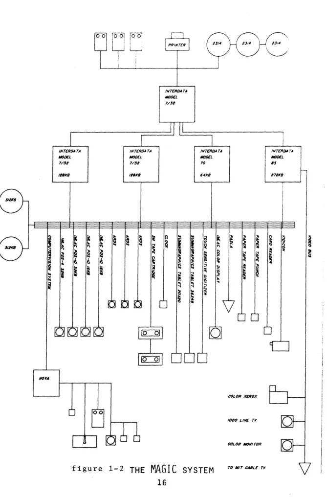
The organization of the MAS system is depicted in figure 1-1. Each program and the main data structures are explained In the appendix of this paper,
The is shown MAS uses
hardware configuration of MAGIC in which MAS is installed in figure 1-2.
MINICOMPUTER memory 64k bytes IMLAC DISPLAY memory 32k bytes MOVING HEAD DISK memory 2314m bytes
figure 1-1 THE
MAS
SYSTEMDISPATCHER
INITIALIZATIONCALLIN
MOVE SPACESCALMV
CHANGE VIEWCALLVW
ARRANGECALLAR
MAKE SPACESCALLSP
PERSPECTIVECALLPP
CONSTRAINCALLCO
PERSPECTIVECALLRL
figure 1-2 THE
MAGIC
SYSTEMCOL OR XEROX
/000 LINE TV
COLOR MONITOR
EXPLANAT ION
OF MAS SYSTEM'S
. .!. . .-T
figure 2-1
MA vIM
WIT
Il-1 SCREEN FORMAT
The MAS system uses a calligraphic display with two
screens refreshed from the same buffer. Both screens have the same format shown in figure 2-1. The format includes a display window, two menus, a key figure, a scaling
indicator, indications for xy and z axis and the name of the
projection type.
Il-1-1 Display Window
The display window is the area in which the spaces are displayed. The size of the display window is
inches square in shape. The
coordinate system of the display window is the orthogonal two dimensional coordinate field of
the three dimensional data space. All the figures displayed ih the display window are clipped at the border of the display window.
11-1-2 Menus
Two menus are stacked one above the other, formi ng a column to one side of the screen. The side on which they appear is determined by the user: for right handed users, the menus will appear to the right of the display window; for left handed users to the left. This 'is done so that figures displayed in the window area will not be
II E SPACES OwM M ~S NOmDESia PVcTIVE WlIT ~1 CIPAILATION LviMO M figure 2-2 ~a4C 1011 0 O ONTUT4,LO
WHICH HM" DO YOU POINT UITH, L OR R 7
JR0I T MAN'
figure 3-3
points at an item in the menu list. Figure 2-2 shows the screen format for the left handed user. The handedness of the user is queried at the very begining of
the design process ( figure 2-3 ).
The upper of the two menus will be refered to as MENU1 throughout this paper. This menu lists the various modes in which MAS can operate; these are modes into which the user can put himself as he wishes. In MENU1, the item "NODES/BOXES" and "QUIT" have somewhat different functions.
"QUIT" is the item that should be
pointed at to terminate the MAS system and to return to the
operating system. "NODES/BOXES" is
the light buttom to which the user
points when he wants to change the representation of the spaces:
between GRAPH and CUBOIDS. Both representations have their own
CHANGE VIEU NODES/BOXES MAKE SPACES CONSTRAIN ARRANGE PERSPECTIVE OJIT figure 2-4
MENU1 which is shown in figure
2-4. The other light buttons include: "CHANGE VIEW", "MAKE SPACES", "CONSTRAIN", "MOVE
SPACES", "ARRANGE" and
"PERSPECTIVE" The user is informed as to which mode he is In by a blinking technique. Note: blinking is achieved by pointing at the light button with the light pen.
The menu area below MENU1 is refered to as MENU2. This menu is changed as different modes of
IENU1 are "activated". These subordinate menus will be
explained later in conjunction with descriptions of the modes of MIENU1.
CHAO VIEU NOcs-SOXES MAKE SPACES COITRAIN MOVE SPACES PERSPECTIVE QUIT figure 2-4
Each screen has a small key figure at the upper right hand side corner. This key figure has two little arrows, one of which is always blinking. The blinking
arrow indicates the viewing direction of its own screen. The other non-blinking arrow indicates the view of the other screen.
(figure 2-4)
1l-1-4 Scale, Axes and Display Type Name
On each screen, there are two axes which indicate a pair of x, y and z directions. Under the
display portion of the screen, projection type name and scaling Indication appear. The proper unit of the scale is chosen according
to the current scale.
11-1-5 Cursor
The cursor is a indicator of the cutting location, direction and width of the other screen. The cursor does not appear when the viewing directions of the two
screens are either the same or the opposite. The active cursor has an associated dotted line which
indicates the depth of field of the other screen.
Both cursors and the dotted line are positionable with the light pen. The cursors are used to change the view direction of the screens ( precise explanation is
is cut by the active cursor, this space appears on the other screen brighter than the other spaces. This dfference of intensity allows
the user to separate the plane in which he is working from the
11-2 GRAPH AND CUBOID REPRESENTATION
MAS has two kinds of space representations; one of which is the GRAPH (node and link)
representation, and the other is the CUBOID space representation.
MAS deals with both the
absolute and the relative three dimensional location of spaces, and the three dimentional sizes of spaces accoding to various
constraints.
In the GRAPH representation, the node denotes the location of the spaces and the link denotes the adjacency constraint. In the CUBIOD representation, each space
Process Typo oF Representation GRAPH CUBOID CHANGE VIEW MAKE SPACES CONSTRAIN Adjacency Overlap Enclose Max. Dist. Mn. Dist. Area Proportion Dimension(x y z) Attributes MOVE SPACES ARRANGE PERSPECTIVE
Change Eye Loc. Real View f igure 2-5 0 0 0 0 0 0 0 0 0 0 0 0 0 0 0 0 0 0 0 0 0
has actual volume instead of the
adjacency constraint. These two kinds of representations can be chosen by pointing at the item "NODES/BOXES" in the MENU1 list.
But some processes are
particularly assigned to either type of representation. (figure
2-5)
11-2-1 GRAPH
The Architecture Machine Group is currenity working on a project called YONA. This project derived
its name from Yona Friedman, a consultant responsible for its basic philosophy (4).
assists the non-designer to design his/her own home. The basic
concept of this project consists in the difficulty of comnunication between the user and the designer of the house which should be
designed according to the personality of the user.
YONA's underlying structure is In graph theory. Nodes and
linkages of the graph denote
spaces and connections among them. Since the connectivity of spaces is one of the most important and basic constraints in early stages of architectural design, this graph representation is very useful to roughly capture the
relationship between spaces. Especially, in terms of
architectural design, it is
important to determine whether or not the graph is either planar or non-planar because planarity of
the graph assures the possibility of a solution. The planarity, however, applies only to two
dimensional objects. Therefore the planarity no longer has meaning in
the MAS system. Even so, the graph itself is a useful vehicle in
order to capture the relative location of spaces in three dimensions.
11-2-2 CUBOID
Cuboid has been chosen to
represent actual spaces. In part, this is because cuboids minimize computational complexity. And, in part, this is because cuboids approximate a real
3-dimens i onal i ty, i nd i g i nous to large portions of the built environment.
Each cuboid is defined by six variable descriptors, which
contain the data necessary to describe the position and size of rectangular volume in Euclidean space. Therefore it is impossible to rotate each space in the MAS system.
1 1-3 MODES OF MENU1
feg ur 20
2-f igure 2-6
aO 'lieu
"001,00
In this section, the MAS system's capabilities and
functions are explained according to the modes of MENU1. When HAS i s started, the user will be asked which hand he points with. The
user should type "R" or "L". Then the mode of the system Is set up at the "MAKE SPACES" mode, and the
status of the two display screens are initialized as in figure 2-1 and figure 2-6.
11-3-1 General Typed-in
Commands
4 type-in commands exist which can be typed in anytime. These are
, "SAVE", "GET" and "NO [ENU".
"fil
This command allows the user to return
temporarily to MAGIC, the operating system. Then to continue the design process, "CO" must be typed.
"SAVE"
This command allows the user to save current data. He does this by typing the file name together wi th "SAVE" command (i.e. "SAVE
IT"). Otherwise, he will be asked the file name.
"GET"
This is the complement of the "SAVE" command. With this command,
previously stored data can be retrieved. The user does this by typing the file name to be retrieved together with "GET" (i.e. "GET IT"). Otherwise, he will be asked the file name.
note: If "SAVE" or "GET" fails, the system will be left in MAGIC. This affords the examination of the file name in the directory. To continue the process, "CO" should be typed.
File names are associated with the suffix ".DATA", but must not be named
expl i ci tl y as such. The system does it
automatically.
"NO MENU"
This command allows the user to erase MENU2. To retrieve MENU2, he
should point at the appropriate Item of MENUl. If he Is in the
"MAKE SPACES" mode, he should call the menu again.
11-3-2 CHANGE VIEW
This mode allows the
....0 .. 6. v i t. uMM view CM-,11 NU
'"""""".,
CO".WA'N MM VIW Is~a ve figure2-'I
to the display screens. It's
functions are somewhat janitorial and are not a design aid per se (figure 2-7).
Menu for C1HANGE VIEW
7 (figure 2-8) THIS SCREEN OTER SCREEN MOVE VIEW SHINK VIEW EXPANO VIEW figure 2-8 - THIS SCREEN -- OTHER SCREEN
-These two light buttons are related to submodes, in which the behaviour of the cursosr is
different. The default is "OTHER SCREEN". Accordingly the item "OTHER SCREEN" is blinking. In order to change, it is nesessary to point at the opposite item with the light pen.
Submode "THIS SCREEN" --- item THIS SCREEN is blinki ng
By moving the cursor, the user
can change the viewing direction of that screen.
This submode is necessary to get the same viewing direction on each screens.
Submode "OTHER SCREEN" --- item OTHER SCREEN is blinking
By moving the cursor, the user can change the viewing direction of the other screen.
This submode is necessary to change the location of sections on one screen without changing the view of the other.
MOVE VIEW
-"""" of
+
f igure 2-9
This submode allows the user to pan. By pointing at this menu item with the light pen, the user can go Into the MOVE VIEW submode.
In this submode, the window can be moved over the data base by following the position of the cross which has appeared at the center of the display window. To terminate this submode, the user must point at the item "RETURN" with the light pen. (figure 2-9)
- SHRINK VIEW
-- EXPAND VIEW
-While pointing at either of these light buttons, the image is
ClAMdE VIEW
figure 2-10
...' es. uE
ENTRY CiWM VIEU
STAIRCASE r SA
C0O1IN
CIRCILAIIO
OTR SCD.
L 'le"0 Seli V.U
o - FLO PLAN .--.00 VIN
z'
f igure 2-11a
scaled up (or down). For every four times the image is redrawn, the scale becomes twice as large (or small) as before.
When the scale of the screen reaches the scale of the other screen, the movement will
terminate. If the user want to continue the same manupulation beyond this point, he has to release the button of the light pen and push it again.
2-10) C."Md VIEW P S@EillE 9.UE VIEU 1141 "'*:"" (figure
Screen manupulation for CHANGE VIEW
Cursor
In order to change the viewing direction or the cutting location of either screen, the user should move the appropriate cursor with
Y
NOWE VACS CONSTAIN PeRSVIVE ____________ .I.v13 figure 2-12a .'..' 4!6iE s.' M * """" ... f igure 2-12b 11-3-3 MAKE SPACES
This mode allows the user to create spaces or to delete spaces. This is the initial mode when the
MAS system is started.
It
the light pen. When he needs to move the non-active cursor, he should point at the either side of the display window with the light pen, whereupon the cursor will appear under the light pen.
When the cursor is let go near the one of the four sides of the display window , the previous
status of the screen will return.
By moving the dotted line which
belongs to the active cursor, he can change the depth of view of the screen. (figure 2-1la, figure
emS va~S 39 P"IrLOaft PLAN f igure 2-13 ENTRY CIRCULATION KITCHEN DINING ROOM LIVING ROOM BATHROOM BEDROOM STUDY STAIRCASE PATIO CLOSET figure 2-14 mum we= inI i.... (figure2-13)
Menu for MAKE SPACES
No menus are built-in for this mode, rather, the user has to prepare menus Otherwise he has to type In space names one by one. These typed-in space names appear in the MENU2 area. The length of these space names cannot exceed 12 characters.
When he has a prepared menu, he can call for it by typing its file name preceeded by "MENU ", then menu items will appear in the
MENU2 area. (figure 2-14)
Any name typed after that will appear in the MENU2 area, also.
Procedure to Make Menus:
EDIT HOSE.ENU EDIT U I ENTRY*150 2 CIRCULATIONs120 3 KITCHCN8330 4 DINING ROOMs250 5 LIVING R00M*500 8 BATHROOM'*110 I BEDROOM'240 8 STUDY*200 9 STAIRCASE*160 10 PATIO'800 11 CLOSETS 0 figure 2-15
At the MAGIC level, the user can make a file which contains space names. The file name for this space names should have the suffix ".MENU". Names can have up one blank, but as above cannot exceed 12 characters in length.
Each space name can be associated with an area
constraint. To specify this area constraint, the user must put the number of desired square feet
immediately following the space name, separated by "*".
Each file can hold up to 12 space names. (figure 2-15)
Screen Manipulation for MAKE SPACES
On either screen, the user can make a space by pointing at the name in the MENU2 list, and then dragging it onto the display area. ME SPACES it .. .. ..
Y
TChAIN HOW WAGS PM TIVE ,UIT D~tT Ce01LATIO. KITOHM OINND A LIVINO 001M.. PATIO CLOKT figure 2-16aA space is thus created where 4-figure 2-16b MAKE SPACES STUID2 ZCCLATIN nBATHROoA3 0@BATHVO *BEDRO 3 -e S EROOpe figure 2-17a
the name has been dropped, third dimension of and the its location EITOEN STAZMAS 01410M VIEW OOSAI! PTIA MOE .PACS PERIECTIVE Quit O" CInCUATION KITCEN DINI, plM LIVING MO BTamam STLOK STAIRAE PATIO svAXE SACES OaM VIEW CTitlE CImATIMA KITCT Kii,6 MA LINiMA MACS osate m STAIE.E ATIO PaT
and pushing the button quickly.
11-3-4 CONSTRAIN
is
Z
,Is Pe 3 Pel x FRN X-ECTION
determined by the position of the screen surface. (figure 2-16a, figure 2-16b)
The spaces that already exists inside the display area can be moved by the 1 ight pen. ( Note: low intensity figure is not sensi tive wi th the l ight pen.) (figure 2-17a, figure 2-17b)
A space is deleted by pointing
at the space with the light pen
Y
This mode allows the user to specify a variety of constraints.
---sa It is the kernel of the design
01 method implicit in HAS. (figure
2-18)
0
. 0 .. Menu for CONSTRAIN
figure 2-18
Each item of the menu
represents a submode, within which the particular tasks are
excutable. The current submode blinks. In order to move from submode to submode, it is only
necessary to point at another
light button.
There are two kinds of
constraints; one of which deals
with the relationships between two
spaces, and the other which deals with the attributes of a single
ADJACENT OVERLAP ENCLOSE MAX.DIST. MIN.DIST. AREA PROPORT ION DIMENSION ATTRIBUTES PRINT OUT figure 2-19
of ADJACENT, OVERLAP, ENCLOSE, MAX.DIST. and MIN.DIST., the
latter group consists of AREA, PROPORTION, DIMENSION(X Y Z) and ATTRIBUTES.
The specification of each is posted above the display area.
(figure 2-19)
- ADJACENT
-This submode only relates to the graph representations. By a two step process, the adjacency constraint can be specified
between two spaces. The result is that the machine will try to make the two spaces tangent, at least corner to corner.
The first step is to activate a space by pointing at it with the light pen or by typing its name, thus causing it to blink. Then,
ADACENT ENTRY STAIRASE CO61MIN CEA TIWE WlIT Iaa~Ia. ATMIMM' PawT a)? figure 2-20
the adjacency constraint can be specified by pointing at any other space or typing any other space name. Finally, a line appears
between the spaces. (figure 2-20) To deactivate the space, the user points at it with the light pen or types its name.
By the same process, this adjacency constraint can be removed.
- OVERLAP
-This constraint same manner as the constraint.
This cause the overlap between tw is input in the ADJACENT machine to allow o spaces. - ENCLOSE
-t
CZtLtLATION 0OINING OBATeoaP40HTA IW4
MLOET
This constraint can be input in the same manner as the ADJACENT constraint. Its application is important in evolving the envelop of the building, in handling the
location site of the building.
- MAX.DIST.
-This submode is only executable in a cubold mode of
representation.
The constraint MAX.DIST. means the distance within which the machine can move two spaces is limited.
The process of inputting data is similar to that in the ADJACENT submode. The f i rst step
(activating the space) is exactly same. The second step is dragging
any other spaces wi th the l ight
pen to specify the distance which is posted in the information area. The user also can specify the
distance by typing in the space name and the distance.
Distance is calculated from the surface of the space to the
surface of the other space in three dimensions.
- MIN.DIST.
-This submode is only assigned to cuboid representation.
This constraint is input in the same manner as the MAX.DIST.
constraint.
It causes the machine to move spaces beyond the distance
specified in the MIN.DIST. submode.
- AREA
-This submode is only assigned to the cuboid representation.
In this submode, the size of any spaces can be changed with the AREA BE100@ 3H at.
light pen. The user can also input the data by typing the space name and its square footage. (figure
2-21)
C AT
figure ?- PROPORTION
-f igure 2-21
This submode is only assigned to the cuboid representation.
The proportion is the ratio of the length of the X edge and the Y edge of the space, and it is
represented as a percentage. The process of inputting data
is the same as that in the AREA submode. - DIMENSION(X Y Z) -JSTAIKhE 21L figure 2-22a Z DZINcSIi STAIM
t
M ?t. If i 2 u -2UC2Ib *SON? figure 2-22b "'Nw CH M altow.- W
-" - ---Mow. .IM .laf6,0l M"' MaThis submode is also only assigned to the cuboid
representation.
This submode is divided into three lower submodes, where the user can input the X, Y or Z dimension respectively.
To change the lower submode, the user should point at the item "DIMENSION" with the Iight pen. The indication of the current
lower submode (X, Y or Z) will appear under the item "DI[MENSION".
(figure 2-22a, figure 2-22b) note: AREA, PROPORTION and
DIMENTION (X, Y) are related to each other. The data that is inputted
L I,1A R.O - date .1.1. AMA P.,...TI.. DIP I . Cx Y) pe II 0 roo ____________X__ FLOOR PLAN f igure 2-23 CHm vIU "fl2.xvIOI A00 CO&TMAIN -m OUST 0010M MIN.DIST. DIEI6I ATIIUR PRINT OUT
last has a priority in this system.
When the user type the space name with the datum 0, the user delete the data of AREA, PROPORTION and DIMENSION (X, Y)
altogether. (figure 2-23)
- ATTRIBUTES
-This submode has three lower submodes, which are "fixed", "rigid" and "<fresh>". These attributes are related to the behaviour of the spaces in the ARRANGE mode. Namely, the machine cannot move the "fixed" spaces, and the machine cannot change the size of the "rigid" spaces.
In the "<fresh>" submode, the user can delete the "fixed" and "rigid" attributes of the spaces.
o 4/).7 / 76 159: 39:N0
ADnr ENT
LtiRY r T RCUiLA TI (iN
C.I R y r, T fCHEN
STAIflrASE CIRCL T T 11
K TI CEEN V- TiNNG 90 rhR (-.LAIla CEIMG FO
O1fROULATTON LiV[NG FO01'!
C [IER'UL 10 I B nD;
'Tzr'ULA IT jN q rp n111
STAIPrASE V WrCLAI TLN.
bATriR Uud/ JEDrd007.
biAThibUE? BFDRuOM OrirULAITON) J ED R)0'0 C ICULiA 101%) 6EDR0I0-/ bEDROih/ STJDY EEDR(00 i STULI? bVERLAP LTV~t!G ?(,U' FPr I' ENrLiSE tAX DIST-r.I h . IST. E.NThY dEDROW' ~-~~~~~~~---~~---~---ENIRY IA ft., %, I ft., I tt. C I d'ULAiT T UN IsI sfti . , , i i . t , /.17 sft., 18 s ., it., 14 P ft , O , t. 1. it , LTV TNG P0jpO ()I I tft It I) sft . , f t. tt., S st. t I %, f t. it , 494 sft., 177 1, l tt., U CLLSE I 49 sft., 9/ %, 7 ft., 6 it. E Er Le P U sft., %, I ft.. 0 Lt., bATHR OOM/ 101 Ef t. o %, f t., t t. U sft., 0 %, u ft., o it. STUDY U sft., 0 %, STULi 1)0 sft., 0 BEDR00I3 13 sft., t af , CTCULATTONi 1.4s sft., 0 , PRINT OUT -//, ft. , . ft. I it. tt., ft.
By pointing at this item with the light pen, the user can get the data of the constraints listed on the line printer. (figure 2-24)
After printing, the submode
It.
will be set up to the ADJACENT submode. r ft. I t. n it. ft., U , ft. II tt. l tt. ft. ft., 0 ft., 0 ft. i ft., U it., a tt. 0 ft., o it., ) ft. a ft., 0 it., 0 ft. ft. 11-3-5 MOVE SPACES
This mode only relates to the graph representations. The user's main task in this mode is to
initialize the location of the spaces in three dimensions from which the machine begins to
f igure 2-25 MIRROR x MIRROR Y ROTATE + ROTATE -SHRINK EXPANO DEACTIVATE PLAN figure 2-26 CKM VIEU MWE SPACES MOKE SPACES PW@CTItVEQUThIT
suboptimize the configuration. (figure 2-25)
Menu for MOVE SPACES
Each item of the menu
represents capabilities which can be excuted by pointing at the Item. These operations would be applied to the active nodes, if any. Otherwise, these are applied
to all nodes. (figure 2-26)
- MI RROR - MI RROR
x
Y
By pointing light pen, the mirrored Image
at these with user gets the of the active the part IMOM x ROTATE-ExMat
of the nodes about the X or Y axis of the screen.
active nodes, be applied to
If there are no
this operation will all the nodes.
- ROTATE + -- ROTATE -
-While pointing at these with the light pen, the active portion of the spaces will be rotated clockwise(+) or
counter-clockwise(-). If there are no active nodes, this operation will be applied to all the nodes.
- SHRINK -- EXPAND
the light
will move there are operation nodes.
pen, the active nodes together or apart. If no active nodes, this is applied to all the
- DEACTIVATE
-bu be
By pointing at this light
tton, all the active nodes will deactivated.
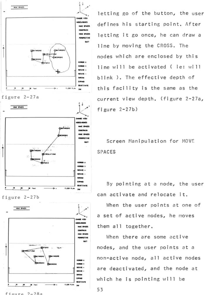
- INK
-This facillity is used to activate more than one space. By pointing at this light button, the track CROSS is turned on. By
dragging the CROSS to the appropriate location without
MOVE SPACES At figure 2-27a A. FLOOR PLAN 1W $e h so -t
At
*mcrn@ En tIz O NaUMT W -s~wa L poo ., - x F LOM PLA mI All
SALOVA
S S I
figure 2-27b can activate and relocate it.
HOW VACES ... A... ... ...l S IS N U f~t A LKS A.M GKVM VID) "M W0AS ---M.... "na x -- a WtAil -'S~ DIXTU.T ENWA
When the user points at one of a set of active nodes, he moves
them all together.
When there are some active nodes, and the user points at a non-active node, all active nodes are deactivated, and the node at which he is pointing will be "ME go=S 1im x MINIM V EmTA. -WAVE T.atiE
letting go of the button, the user defines his starting point. After letting It go once, he can draw a line by moving the CROSS. The nodes which are enclosed by this
l i ne w I I I be a c t i va ted ( i e: w 1 1 blink ). The effective depth of this facility is the same as the current view depth. (figure 2-27a,
figure 2-27b)
Screen Manipulation for MOVE
SPACES
t
I ~ ~ 3 ?w ~ Ps XNP~ figure 2-28b lOVE SPACESY
figure 2-28c CIM VIEUJ .-DEAe COMB1RaN POVE SPACES GIlT oem vil MMmm MTA1E . NTATE-2WIT DACTIVATE LO OR PLNA Z -- -Ae-CO--IN ROVE WACES CUBITAIN 4IMM VcE NTillE -I A N1 A ROTATE E~M DEACTIVATE FLOOR PLAN 1 MAK]IA OWM lAN ESRAII 1-MCIa GUIlmovable. (figure 2-28a, figure
2-28b, figure 2-28c)
1 1-3-6 ARRANGE
This mode is only assigned to the cuboid representation. In this mode, the machine will
automatically change the location and the size of the spaces in three dimensions to achieve the constraints which have been input. This operation is applied only to the deactivated spaces. This
operation is explained in the section, Background Movement for ARRANGE. At any moment, the user
can interrupt the machine's action and excute certain tasks. (figure 2-29) DEACTIVATE MOVE DALYv RESMat ONLY SE LJWS 4~. A~b~S1*'~ AM 54 ... U;4U ... ...
Menu for ARRANGE DEACTIVATE MOVE ONLY RESHAPE %~L Y SEE LINKS PLAN figure 2-30 (figure 2-30) - DEACTIVATE
-By pointing at this light
button, all active spaces will be deactivated.
- MOVE ONLY
-By pointing at this light button, the user enters into the MOVE ONLY submode, in which the spaces are moved and not reshaped. To move the space, the user points
at it and drag it with the light pen.
To terminate this submode, the user should point at it or
"RESHAPE ONLY".
- RESHAPE ONLY
-By pointing at this light button, the user enters the
RESHAPE ONLY submode, in which he can only reshape the spaces. To reshape the space he points at i t and squeezes or expands it with the light pen. In this submode, by pointing at the name of the space, the user can grab i ts corner
easily. Therefore he can reshape two sides of the space
s i mu 1 taneous 1 y.
To terminate this submode, the user should point at it or "MOVE ONLY".
- SEE LINK
-While pointing at this light button, the configuration of the i. spaces is displayed in a graph .MV." representation on both screens.
"" (figure 2-31)
This facility is used to see the current adjacency requirements in the ARRANGE mode.
MTVA1E
,M8M QQ.9
M Ly"si 8 1 a 38 Nee I FLOWR PKAN 1
f igur e 2-31-IN
This is the same facility as
that in the "M1OVE SPACES" mode.
Screen Manipulations for ARRANGE
By pointing at the name of a space and dragging it with the
light pen, the user can relocate it to the new position.
By pointing at the edge of the " space with the light pen, the user
W6ISO
can change the size of the space
by varying one dimension (ie: that
perpendicular to the edge), or by pointing at the corner of the space, he can change both the
, ?qL --o F- P- "" W dimensions. (figure 2-32)
figure 2-32
Background Movement for ARRANGE
While the user arranges the spaces, the machine keeps
suboptimizing the configuration of spaces in accordance with the
constraints specified by the user.
KEEP OUT ( default function )
This is a default, avoiding the overlap between spaces.
The sizes of the spaces are modified.
Two different movements: Vertical Movement:
When the Vertical overlap between spaces is less than the 1/3 of the floor height (3'4" -- based on the default floor height of 10 feet), the vertical movement of the upper spaces will take place In an
upward direction only.
Horizontal Movement:
When the vertical overlap between spaces is more than the 1/3 of the floor height (3'4" -- based on the default floor height of 10 feet),
horizontal movement will take place.
ADJACENT
The two spaces are moved to touch at least corner to corner in three dimensions. Vertically
spaces are only pulled down.
The sizes of the spaces may be modi fi ed.
OVERLAP
The two spaces are moved to touch at least corner to corner in three dimensions and KEEP OUT
function is not applied to them. Vertically spaces are always pulled down.
The sizes of the spaces ray be modifi ed.
ENCLOSE
The two spaces are moved to enclose each other.
The sizes of the spaces are not modi fi ed.
MAX.DIST.
When the current difference in the Z direction is greater than that specified by the user, either one of the spaces is pulled down. Otherwise both are moved
horizontally. The distance is always calculated in three dimensions.
The sizes of the spaces are not modified.
MI N.DI ST.
Two spaces horizontally dimensional d
are moved only
to satisfy the three istance between them.
AR EA
The area constraint (this is specified when spaces are made, and is not that specified in the
CONSTRAIN mode) can be changed.
This has the first priority among area, proportion and dimension(x,y).
PROPORTION
When no proportion constraints have been specified, the existing proportion is used to arrange
spaces. In this proportion will between 50'7 and case the be somewhere 200%. DIMENSION
X -- When specified, the machine adjusts the X dimension of the space.
Y -- When specified, the machine adjusts the Y dimension of the space.
Z -- When specified, the machine adjusts the Z dimension of the space.
The machine adjust only the upper edge of the space.
ATTRIBUTES
machine does not modify the location of the space.
rigid -- When specified, the
machine does not adjust the size of the space.
1 1-3-7 PERSPECTIVE
This mode allows the user to display perspective with hidden
line removal. (figure 2-33)
figure 2-33
Menu for PERSPECTIVE
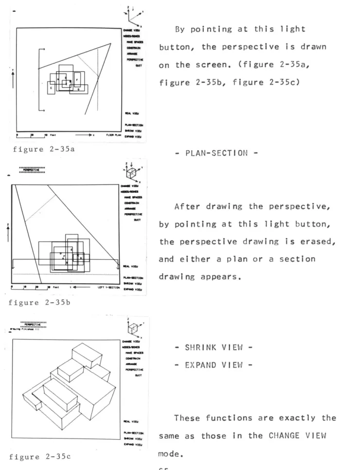
REAL VIEW (figure 2-34) PLAN-SECTION SHRINK VIEW PLAN EXPAND VIEW figure 2-34 - REAL VIEW
-t
bUAM VIVU CMMM v0"EU PEMMECIVE GCIT "INK Vigil ....By pointing at this light button, the perspective on the screen. (figure
figure 35b, figure 2-is drawn 2-35a, 35c) 2-35a - PLAN-SECTION -Z4n i , I-: MT MA. vie ... . .... After drawing by pointing at t
the perspective drawi and either a plan or
the perspective, his light button, ng is erased, a section drawing appears. figure 2-35b oan vis alT PLANMCTI.E EilPaU vimy - SHRINK VIEW -- EXPAND VIEW
-These functions are exactly the same as those in the CHANGE VIEW mode. figure 2-35c -COAT MA va fLU-MaC?,
X FLOO 113sON1 viIN
figure
PEPCTIVE mamt --CTivE own MWT
t11119TV
-t ff" V=t .448M.CTION '"",v"", .___ .,..,____ figure 2-36a *Vo" , 101w" II OWN vow -a .iT1...v
W
getis. vis __________ Ognme vise figure 2-36b umv...;g ;g.. Mona -11 *AT'K,
M. Vim A-ECT--1ess0 vim El.~. vm0Screen Manipulation for PERSPECTIVE
On each screen, scope figure which view location and d the perspective, By dotted line with th the user can change of the eye position its solid line with the user can rotate di rection. there is a indicates the irection for grabbing its e light pen, the location By grabbing
the light pen, the view
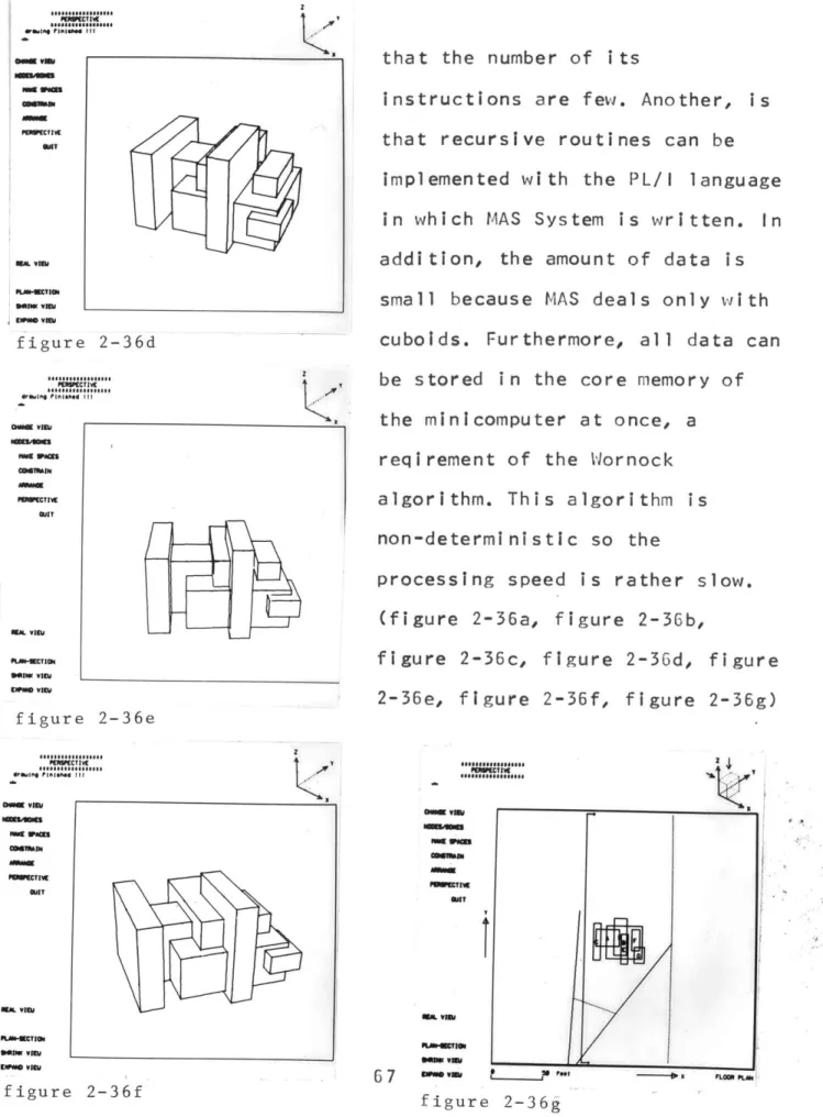
Algorithm fo hidden-line removal
The hidden-lines of the
perspective are removed by means of the Wornock algorithm. One reason for its implementation is
z
~ETIWE *amW Vnla __________ figure 2-36d POVfC IW ----CHOL VMU OlM.TIV QIT
GetT
oLrs-CT e figure 2-36e I PIMPETv Cmma MMCTIVI QUIT WE& VIIIa 2 that recursive cubolds. algori thm. non-deterministic so the processing 2-36e, figure 2-36f, So# a ITI 110*1,#1 Wm vft 67 ***o -o 014''that the number of i ts
instructions are few. Another, is routines can be implemented with the PL/I
in which MAS System is written. language
In addition, the amount of data is small because MAS deals only with
Furthermore, all data can be stored in the core memory of the minicomputer at once, a reqirement of the Wornock
This algorithmis
speed is rather slow. (figure 2-36a, figure 2-36b,
figure 2-36c, figure 2-36d, f i gure figure 2-36g)
I I I
APPLICATION
III APPLICATION (Experiment with an architect)
In comparison to "real world" design tasks, the range of the problems with which MAS can deal, Is rather basic and primitive. To test exactly how primitive, and to examine the current
direction of MAS, a case study was undertaken with a practicing architect. This case study provided the opportunity to investigate
the system's capabilities as used by a professional designer unfamiliar with computer aids.
The collaborator for the case study was Herman Zinter, an architect at The Architects Collaborative (TAC). He currently is
involved in the design of several hospital facilities, one in New York and others in Minnesota. He also has teaching experience.
I 1-1 FIRST MEETING ( March, 31, 12:I45 pm - 2:15 pm, at MIlT )
An initial meeting was held with Herman Zinter and two of his colleagues from TAC, Ken schwarz and Bill Sommerfeld. The purpose of this first meeting was to demonstrate MAS' capabilities and to explore the posibility of their participation in an experimental application. For demonstration purposes, a hospital-like building was designed with MAS. They asked numerous questions during this
session mostly about the capabilities and functions of the system.
After seeing the demonstration, they felt that MAS was not well suited to their goals. They felt that the system functioned best for "fine tuning" a given configuration rather than for
generating a broad range of alternatives, as they had hoped. They decided, however, to try HAS in an experiment anyway, and they
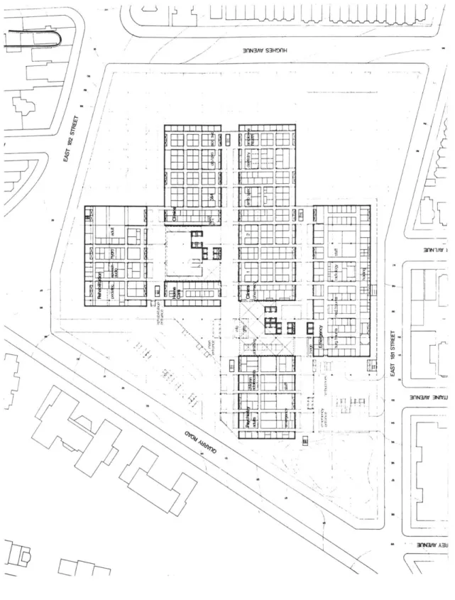
suggested that the Fordham Hospital, a project in their office, might be suitable for this experiment. The Fordham Hospital is to
be built in New York, but work is presently suspended for the political reasons. They suggested the Fordham Hospital project because it has been well documented throughout the design process.
A second meeting was arranged to examine the project more closely.
As a result of their comments during the first meeting, scale indicators were installed for each of the screens and two menu items in the constrain mode were changed from "NEAR'' to
"MAX.DIST." and from "FAR" to "HIN.DIST.".
I 1-2 SECOND MEETING ( April, 1, 12:45 pm - 3:00 pm, at TAC )
This meeting was held to develop, in detail, the exact nature of the project to be explored in the case study.
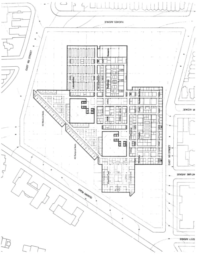
Herman Zinter outlined the design process during the
Fordha-Hospital project (figure 3-1). From his explanation, we tried to identify that part of the design problem which would make a clear and valid test of MAS' capabilities.
Their design process was divided into four steps:
architectural programming; schematic design; design development; and detail design. The project is currently suspended at beginning of the design development stage. During architectural programming,
the user's needs and the legal conditions were studied. in the schematic design phase, the various types of rooms were examined. And in design development, building configurations were generated using constraints from schematic design and the characteristics of the geometry of the site. Their reasoning was composed of a
mixture of the geometric constraints and considerations of the human activities that would take place in the building. Within the capabilities of MAS, it is very difficult to describe the
functional requirements of human activities: circulation,
supervision of patients, management and administration problems etc.
There were additional problems as well. The number of the rooms in the one nursing unit exceeded the data capacity of MAS.
Also, the architects search for a geometric solution had already led to a successful configuration, and it was clear that any alternative approach would just be a deceptive exercise. To make
3nlN3AV S3H~flH f 71 L.JJJ III_ia A AL.UJ
-FT
I l
I
4 1 F1 T __- annaL3WJ '7 3fe F aV A1H3nlN3Av
S3H~fl9-/
--
3flN3Av 3mio'figure 3-1 Fordham Hospital f- - -- - - ---
~KKLVI4 fT
z j l i
wwm SJW
h
i
figure 3-1 Fordham Hospital
73 140OH -- 3Av 3wvi.*IO v -1 r -av 1nNa3M Mun
matters worse, the solution was heavily dependent upon a rather unique, non-rectanglar arrangement.
After considering these problems, it was suggested that we explore schematic configurational alternatives at the department rather than at the room level. This seemed a good problem to address with MAS, since the floor area of the hospital
necessitated multi level, while the adjacency requirements are best solved on a single level. Furthermore, it was agreed that the site size could be varied to explore the consequences of fitting the building on different sites.
11 -3 THIRD MEETING (April, 5, 12:30 pm - 2:00 pm at TAC )
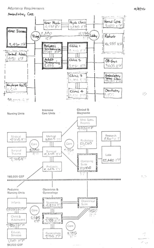
Based on the second meeting, Herman Zinter prepared a diagram of the "Adjacency Requirements" between departments of the Fordham Hospital project (figure 3-2). These were modified to fit MAS's
data capacity. That is some of the strongly connected department were combined, and, to simulate the three dimensional arrangement capabilities of the system, two elevator shafts were added as vertical linkages (figure 3-3).
Adjucency Requirements
I
~rR~jW~ ~1&~dt~CcI
i~C~I
~ 3~6(~') ~"rf ~' 1~~' ~i') -lL~~b~IflK.~LAAAA ~ I i'f) Nursing UnitsIntensive Clinical &
Care Units Diagnostic
figure 3-2 Adjacency Requirements
Adjacency Requirements A-4 ' hkcrW rTYtfl
Ir
IVa-IVi
1
CitZ - 1 q4.~0 ii , rf41 Nursing Units Intensive Care Units Clinical & Diagnosticfigure 3-3 Adjacency Requirements
4-4P
I)