INSTITUT POLYTECHNIQUE DE GRENOBLE
N° attribué par la bibliothèque
|__|__|__|__|__|__|__|__|__|__|
T H E S E pour obtenir le grade de
DOCTEUR DE L’Université de Grenoble délivré par l’Institut polytechnique de Grenoble
Spécialité : « Micro et Nano Electronique »
préparée au Laboratoire des Dispositifs Innovants (CEA-Leti) dans le cadre de l’Ecole Doctorale
« Electronique, Electrotechnique, Automatique & Traitement du Signal »
présentée et soutenue publiquement par
Louis HUTIN
le 07 octobre 2010
TITRE: Etude des transistors MOSFET à barrière Schottky, à canal Silicium et Germanium sur couches minces
DIRECTEUR DE THESE: Gérard Ghibaudo CO-ENCADRANTS: Cyrille Le Royer, Marco Pala
JURY
M. AUTRAN Jean-Luc , PROF. (Université de Provence Aix-Marseille 1) Président M. DIMOULAS Athanasios , DR NCSR (Demokritos, Athènes) Rapporteur M. DUBOIS Emmanuel , DR CNRS (IEMN, Lille) Rapporteur M. GHIBAUDO Gérard , DR CNRS (IMEP-LAHC, Grenoble) Directeur de thèse M. LE ROYER Cyrille , ING. (LETI/D2NT/LDI, Grenoble) Co-encadrant M. PALA Marco , CR CNRS (IMEP-LAHC, Grenoble) Co-encadrant M. BŒUF Frédéric , ING. (STMicroelectronics, Crolles) Invité
“Science is the acceptance of what works and the rejection of what does not. That needs more courage than we might think.”
Acknowledgments
The doctoral research presented in this thesis was performed from 2007-2010 at the French Alternative Energies and Atomic Energy Commission (CEA) in Grenoble, within the Leti research institute, NaNoTec Division (D2NT), Laboratory for Electronic NanoDevices (LNDE) which later split to spawn the Laboratory for Innovative Devices (LDI) some time in 2008. My first thanks go to then LNDE Manager Simon Deleonibus, and LDI successor Olivier Faynot for welcoming me in their group, but for also providing me with invaluable mentoring and support for the next steps on my career path.
I would like to acknowledge the members of my thesis jury for their time and effort assessing this work, for their expert comments and constructive criticism as well as their presence at my defense. Thanks to Jean-Luc Autran, Professor at Aix-Marseille Université for assuming the role of president of the jury. Thanks to Athanasios Dimoulas, Research Director at NCSR Demokritos (Athens, Greece) and Emmanuel Dubois, Research Director at Université de Lille I, for doing me the honor of reviewing my manuscript. Thanks also to Frédéric Boeuf, Advanced Devices Technology Manager at STMicroelectronics for agreeing to attend and provide valued feedback during the defense.
I wish to express my thankfulness to my PhD director Gérard Ghibaudo. Throughout my follow-up visits at IMEP-LAHC I have been consistently in awe of his sharpness and quickness to understand and suggest solutions to my technical problems before I even could formulate them clearly. I would also like to thank Marco Pala for his continued support and guidance as my IMEP supervisor.
My deepest gratitude goes to my day-to-day advisor at Leti, Cyrille Le Royer, who first trained me as a Master-level intern. With his obsession for perfect reports, clear presentations and neat figures (though we have had our disagreements about neon-themed color schemes) Cyrille has led me very early on to master the style, only to better focus on substance with applying the same rigor to analysis and scientific reasoning. In addition to offering his time and patience to help me build on solid foundations, his trust, generosity and overall great human qualities have strongly contributed to making my PhD years fulfilling.
In all honesty, I have found LNDE/LDI to be a truly exceptional work environment, and I would now like to thank my co-workers for making me glad and eager to go to work every single morning. I will start the name dropping parade with “General” Laurent Clavelier, then leader of the Germanium integration team, who welcomed me in the 41.23 building on my first day to brief me on push-ups-based disciplinary guidelines and introduce me to the now legendary “pedagogical aide” (which incidentally looks exactly like a massive heat sink). Claude “Yin” Tabone and Bernard “Yang” Previtali, who helped me get familiar with process technology, supervised the fabrication of my batches, provided daily necrology updates at lunchtime and/or heated debates on the existence of organic wine, the impending threat of water table drought or picking Creuse over Corsica as a holiday destination. Arnaud Pouydebasque who briefly joined the Ge team, the smoking breaks team and the squash team (never simultaneously), Maud Vinet who let me test her awesome DGSBFETs and brag about them myself, François Andrieu who let me test his amazing Dual Strained Channel batch and brag about it myself. Among other “fruitful discuteurs”: Professor Alexander Zaslavsky,
Thierry Poiroux, Yves Morand, Olivier Weber, Thomas Ernst, Sylvain Barraud, Phuong Nguyen. Thanks also to some of the LNDE alumni who later split towards LTMA: Bernard Guillaumot, Carine Jahan, Marc Gély, my apologies if I forget some of you due to insufficient memory. To Gabriel Molas and Georges Guégan, I simply say “bravo pour votre excellence” and “I have a DRAM”. Many thanks to our administrative assistants Corine Pantigny, Sabine Revol and Brigitte Gaillard for their life-saving helpfulness, their constant availability and good mood. I shall now proceed with former and current fellow students I will naturally start with the 416 crew (“I want to believe. But…”): Steph, Atsushi, Vince (bequeather of the holy digimon Casio calculator), Jean-Paul & Fred, Guigui dit “la fusée”, Milène, Cuiqin, Veeresh. Moving on to the other side of the corridor: Cécilia, Emilie, Estelle, Tiziana, Jyotshna, Tekto Marc Bockett, Mike, Ramon, Alex, Sophie, Kiichi, PH, Lia, Thomas, Alexandra, Jérôme, Caroline, and last but not least (!) Perrine.
Owing to the nature of my subject, the strong emphasis on collaborative work at CEA and our privileged relationship with IMEP-LAHC, I was lucky to be able to count on the support and expertise from researchers in various groups:
- At IMEP-LAHC: Youla Morfouli, Quentin Rafhay, Martine Gri, Xavier Mescot - At Leti/D2NT, in the Simulation group: Gilles Le Carval, Pascal Scheiblin,
Pierrette Rivallin, Marie-Anne Jaud, Sébastien Soliveres (who left us too soon), Stéphane Koffel, Sébastien Martinie, Brice Grandchamp.
- In the Electrical characterization lab: Krunoslav Romanjek, Mikaël Cassé, Xavier Garros, Jean Coignus, Patrick Grosgeorges, Jacques Cluzel, Denis Blachier
- In the Cleanroom (D2NT/L2MA and DPTS) and Off-line microscopy group: Jean-Michel “Arrhenius” Hartmann, Jean-François Damlencourt, Benjamin Vincent, Vincent Destefanis, Vincent Mazzocchi, Helen Grampeix, Fabrice Nemouchi, Véronique Carron, Maurice Rivoire, François Aussenac, Vincent Delaye, Dominique Lafond, Armand Béché, David Cooper.
Thanks to the other persons I came to know outside of the technical framework of my research project, during conferences or in Grenoble during coffee breaks, who might open this book and wonder why they were not mentioned (“Yes, yes of course you are”).
Finally and most importantly, I would like to specially thank my family who has been a pillar of strength since forever and during these three years in particular. My parents Evelyne and Jean-Marie for their unconditional support, my brother Simon and his wife Claire, my grandmother Elisa, my future parents-in-law Sabine and Henning, and to my amazing fiancée Stephanie.
6
Table des matie res
Table des matières___________________________________________________________6 Introduction générale _______________________________________________________10 Symbols, acronyms _________________________________________________________13 Chapter I. Introduction ______________________________________________________ 22
I.1. Context ___________________________________________________________________ 23 I.2. Schottky-Barrier transistors ___________________________________________________ 25 I.3. Transistors on GeOI _________________________________________________________ 25 I.4. Ge and metallic Source and Drain, a mutually profitable association? _________________ 26
Chapter I. - References ______________________________________________________ 27 Chapter II. Metal/Semiconductor contacts ______________________________________ 28
II.1. Theory of the Schottky junction _______________________________________________ 29
II.1.1. Formation of a Schottky Barrier _____________________________________________________ 29 II.1.1.a. « Perfect contact » limit case ___________________________________________________ 29 II.1.1.b. Imperfect interfaces __________________________________________________________ 30 II.1.1.c. Fermi-level pinning ___________________________________________________________ 32 II.1.1.d. The Schottky effect, or image force ______________________________________________ 35 II.1.1.e. Summary ___________________________________________________________________ 37 II.1.2. Interfacial current transport ________________________________________________________ 38 II.1.2.a. Thermionic Emission (TE) Theory ________________________________________________ 38 II.1.2.b. Diffusion Theory _____________________________________________________________ 40 II.1.2.c. Thermionic Emission Diffusion (TE-D) Theory _______________________________________ 41 II.1.2.d. Field-Effect Emission (FE) ______________________________________________________ 43 II.1.2.e. Minority carriers injection ______________________________________________________ 47 II.1.2.f. Interfacial layer – Tunnel Effect MIS diode _________________________________________ 48 II.1.2.g. Summary ___________________________________________________________________ 49
II.2. Experimental characterization methods ________________________________________ 50
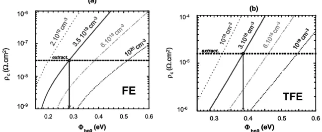
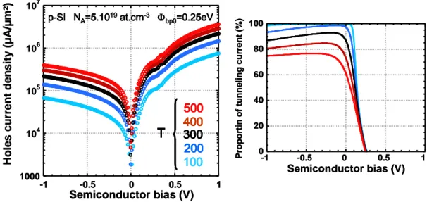
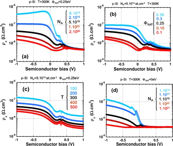
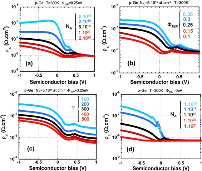
II.2.1. Method based on I-V characteristics _________________________________________________ 50 II.2.2. Activation energy method __________________________________________________________ 51 II.2.3. Method based on C-V characteristics _________________________________________________ 52 II.2.4. Photoelectric measurement ________________________________________________________ 52 II.2.5. Cases of ohmic and quasi-ohmic contacts _____________________________________________ 53 II.2.6. Practical examples for low and thin Schottky barriers ____________________________________ 54 II.2.6.a. Low barriers on moderately doped Si _____________________________________________ 54 II.2.6.b. Barriers on highly doped Ge ____________________________________________________ 56 II.2.7. Summary _______________________________________________________________________ 64
7 II.3. Analytical One-Dimensional Modelling _________________________________________ 64
II.3.1. One-Dimensional band diagrams ____________________________________________________ 65 II.3.1.a. Fermi-level __________________________________________________________________ 65 II.3.1.b. Accumulation and depletion ____________________________________________________ 66 II.3.2. Maximum of potential energy, turning points __________________________________________ 69 II.3.3. Interfacial majority carriers current density ____________________________________________ 72 II.3.3.a. Thermionic Current ___________________________________________________________ 73 II.3.3.b. Field Emission Current in depletion ______________________________________________ 73 II.3.4. Dependences ____________________________________________________________________ 75 II.3.4.a. Majority carriers current density ________________________________________________ 75 II.3.4.b. Ohmic behavior and contact resistivity ___________________________________________ 78 II.3.4.c. Case of metal/Ge contacts ______________________________________________________ 80 II.3.4.d. Summary ___________________________________________________________________ 83 II.3.5. Self-consistent, non-divergent modelling of the image force ______________________________ 84 II.3.5.a. Issues related to the classical formulation _________________________________________ 84 II.3.5.b. Self-consistent expression of the image force potential ______________________________ 85
II.4. Conclusion ________________________________________________________________ 87
Chapter II. - References _____________________________________________________ 89 Chapter III. The Schottky-Barrier MOSFET on SOI substrate ________________________ 93
III.1. Introduction ______________________________________________________________ 94
III.1.1. History of the Schottky-Barrier MOSFET ______________________________________________ 94 III.1.2. Reasons to chose Metal S/D over p/n junctions ________________________________________ 94 III.1.2.a. Series resistance reduction ____________________________________________________ 95 III.1.2.b. Low temperature processing ___________________________________________________ 97 III.1.2.c. Immunity to Short Channel Effects and variability __________________________________ 97 III.1.2.d. Latch-up and parasitic bipolar effects ____________________________________________ 97 III.1.2.e. Relevance of these advantages in the SOI case _____________________________________ 99
III.2. DC characteristics of Schottky MOSFETs ________________________________________ 99
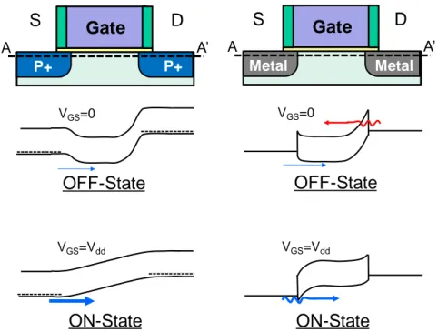
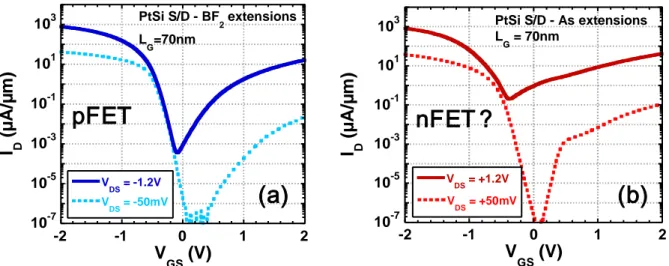
III.2.1. ON-State and OFF-State __________________________________________________________ 100 III.2.1.a. Basic principles _____________________________________________________________ 100 III.2.1.b. Schottky nFET or pFET? ______________________________________________________ 103 III.2.1.c. Ambipolarity analysis ________________________________________________________ 103 III.2.1.d. Influence of doping abruptness ________________________________________________ 106 III.2.2. Subthreshold regime in the Fully-Depleted SOI case ___________________________________ 108 III.2.2.a. Dependence on SOI thickness _________________________________________________ 108 III.2.2.b. Dependence on channel or interfacial doping ____________________________________ 109
III.3. Device integration ________________________________________________________ 111
III.3.1. Damascene Source and Drain _____________________________________________________ 112 III.3.1.a. Single Gate ________________________________________________________________ 112 III.3.1.b. Double Gate _______________________________________________________________ 113 III.3.1.c. Performance and scalability assessment _________________________________________ 114
8
III.3.2. Self-Aligned silicidation followed by selective etching __________________________________ 117 III.3.3. Dopant segregation techniques ____________________________________________________ 118 III.3.3.a. Principle ___________________________________________________________________ 118 III.3.3.b. Silicide thermal stability and ITS dopant segregation _______________________________ 119 III.3.4. Metallic S/D for nFETs ___________________________________________________________ 120 III.3.4.a. Dual S/D Metal for Schottky CMOS _____________________________________________ 120 III.3.4.b. Single S/D Metal for Schottky CMOS ____________________________________________ 124
III.4. Conclusion ______________________________________________________________ 124
Chapter III. - References ____________________________________________________ 126 Chapter IV. Ge-based substrates and devices ___________________________________ 133
IV.1. Introduction _____________________________________________________________ 134
IV.1.1. Early history of (Ge) electronics ____________________________________________________ 134 IV.1.1.a. The first transistors __________________________________________________________ 134 IV.1.1.b. The first integrated circuits and the reign of Silicon ________________________________ 136 IV.1.1.c. “Back to the future”? ________________________________________________________ 138 IV.1.2. Carriers transport in Ge __________________________________________________________ 138 IV.1.2.a. Crystal structure and basic electronic properties __________________________________ 138 IV.1.2.b. A smaller bandgap: pros and cons ______________________________________________ 139 IV.1.2.c. Effective masses, drift velocity and mobility ______________________________________ 141 IV.1.2.d. Summary of the general trends ________________________________________________ 143
IV.2. Germanium-based substrates _______________________________________________ 144
IV.2.1. Ge on Si _______________________________________________________________________ 144 IV.2.1.a. Virtual substrates and graded buffer layers ______________________________________ 144 IV.2.1.b. Thermal cycling _____________________________________________________________ 145 IV.2.2. Germanium-On-Insulator (GeOI) ___________________________________________________ 146 IV.2.2.a. Smart CutTM ________________________________________________________________ 146 IV.2.2.b. Ge enrichment _____________________________________________________________ 147 IV.2.3. Hybrid substrates for advanced CMOS and optoelectronics _____________________________ 149
IV.3. Ge and GeOI CMOS devices _________________________________________________ 151
IV.3.1. Generalities on technological modules ______________________________________________ 151 IV.3.1.a. Wet etching and cleaning _____________________________________________________ 152 IV.3.1.b. Resist stripping _____________________________________________________________ 152 IV.3.1.c. Gate stack and interface with high-k dielectrics ___________________________________ 152 IV.3.1.d. Dopant diffusion, solid solubility and activation ___________________________________ 153 IV.3.1.e. Germanidation _____________________________________________________________ 163 IV.3.2. Ge nFETs: challenges and recent developments _______________________________________ 164 IV.3.2.a. N-type doping ______________________________________________________________ 164 IV.3.2.b. Inversion layer and threshold voltage ___________________________________________ 164 IV.3.2.c. Recent progress ____________________________________________________________ 167 IV.3.3. Focus on the GeOI pFET __________________________________________________________ 168 IV.3.3.a. pFETs on Smart CutTM substrates _______________________________________________ 168
9
IV.3.3.b. pFETs on Ge substrates obtained by enrichment __________________________________ 175 IV.3.4. Status on pure-Ge technology for conventional CMOS _________________________________ 181 IV.3.4.a. Persistent technological bottlenecks for Ge CMOS _________________________________ 181 IV.3.4.b. « Is it worth it? » ____________________________________________________________ 182 IV.3.4.c. Interest of SiGe alloys ________________________________________________________ 183
IV.4. Compressively strained SiGe-On-Insulator (SGOI) _______________________________ 185
IV.4.1. SGOI obtained by Ge enrichment __________________________________________________ 185 IV.4.1.a. Device Fabrication __________________________________________________________ 185 IV.4.1.b. Long-channel FETs characteristics ______________________________________________ 186 IV.4.1.c. Low Vth,p and NBTI ___________________________________________________________ 187 IV.4.1.d. Short-channel FETs characteristics _____________________________________________ 189 IV.4.1.e. Transport enhancement in narrow-channel pFETs _________________________________ 190 IV.4.1.f. Summary __________________________________________________________________ 192 IV.4.2. Dual Channel CMOS by selective SiGe epitaxy ________________________________________ 193 IV.4.2.a. Dual Channel and CMOS process on (s)SOI _______________________________________ 193 IV.4.2.b. Strain characterization in the channel ___________________________________________ 195 IV.4.2.c. Trade-off between mobility gain & Vth shift ______________________________________ 196 IV.4.2.d. D(S)COI short channel devices & circuits _________________________________________ 198 IV.4.2.e. Summary __________________________________________________________________ 201
IV.5. Ge channel Schottky Barrier MOSFETs ________________________________________ 202
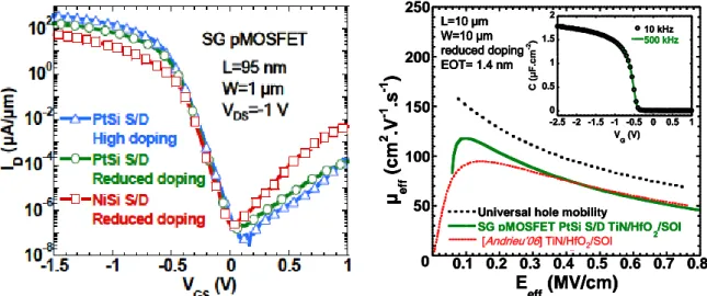
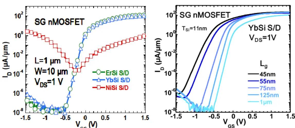
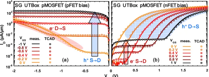
IV.5.1. State-of-the-art, undoped interface ________________________________________________ 202 IV.5.1.a. pFETs _____________________________________________________________________ 202 IV.5.1.b. nFETs _____________________________________________________________________ 204
Chapter IV. - References ____________________________________________________ 205 Chapter V. Summary and conclusion __________________________________________ 224
V.1. Metal/Semiconductor contacts ______________________________________________ 225 V.2. Schottky-Barrier transistors on SOI ___________________________________________ 226 V.3. Ge-based devices _________________________________________________________ 228
V.3.1. Transistors on GeOI ______________________________________________________________ 228 V.3.2. Transistors on compressively-strained SGOI __________________________________________ 229
V.4. Ge channel and metallic Source/Drain_________________________________________ 229
Chapter V. - References ____________________________________________________ 231 Résumé en français ________________________________________________________ 233 Conclusions générale ______________________________________________________266 Liste de publications _______________________________________________________272
10
Introduction Ge ne rale
Depuis sa première démonstration expérimentale par Kahng et Attala il y a un demi-siècle, le transistor à effet de champ à canal Silicium est devenu et s’est maintenu comme le moteur principal de l’industrie du semi-conducteur. Bien que son architecture et sont principe de fonctionnement soient restés essentiellement inchangés à ce jour, ses dimensions physiques n’ont cessé de décroître, suivant la loi de Moore.
Cette loi est principalement ressentie par le grand public sous diverses variantes telles que “mon prochain ordinateur portable sera plus rapide”, “mon prochain téléphone portable sera plus compact et aura plus de fonctionnalités”, qui peuvent toutes se conclure par “et je l’achèterai au même prix dans deux ans”.
En fait, la première formulation de cette loi par Gordon Moore lui-même est qu’en augmentant la complexité d’un circuit pour une surface de puce donnée, en d’autres termes la densité d’intégration d’ “environ un facteur deux par an” (à travers la mise en place des avancées technologiques réalisées pendant ce temps) permettrait de minimiser le coût de fabrication par transistor. De plus, les règles de “scaling” établies par Bob Dennard et al. ont montré la voie vers la diminution de la taille des composants, tout en maintenant la structure de la brique de base transistor, et en obtenant de surcroît un gain en performances mesuré en fréquence d’horloge.
Cette synergie entre considérations économiques et avancées technologiques a été décrite comme “l’horloge de Moore”, un mécanisme autorégulé pour lequel le ressort technique (minimisation du produit puissance×temps de propagation) se synchronise avec le pendule commercial de la réduction du coût par bit. C’est par le biais de cette horloge que la loi de Moore est devenue une prophétie auto-réalisée durant les années dorénavant connues sous le nom d’ère du « happy scaling », ayant perduré jusqu’aux années 2000. Depuis lors, le mécanisme s’est effondré, puisque la réduction de la taille des composants n’a plus suffi à garantir les bonus cumulés d’une meilleure performance et d’un coût de fabrication réduit.
Oublions temporairement les contraintes de réduction de coût pour nous focaliser sur les qualités nécessaires pour faire d’un MOSFET (Metal Oxide Semiconductor Field Effect Transistor) un interrupteur plus efficace. Une façon basique de voir le problème est de chercher à minimiser l’énergie de commutation à l’état bloqué et à l’état passant. Celle-ci vaut 0.5×CG×VDD2, où CG est la capacité de grille du MOSFET, et VDD sa tension d’alimentation. Au premier ordre, les lois du “happy scaling” impliquaient une réduction combinée de VDD et de la longueur de grille LG (et donc de CG).
Le principal obstacle à la réduction de VDDrésulte du fait que les MOSFETs sont des dispositifs thermiques, avec une limite de pente sous le seuil idéale fixée à (kT/q)×ln(10),
11 c’est à dire 60 mV par décade de courant à 300 K. Si l’on désire fixer le courant à l’état bloqué IOFF, alors la réduction de VDD a pour conséquences une plus faible surtension de grille (VDD-VT), et un courant à l’état passant ION plus faible. Inversement, si l’on désire fixer ION malgré un VDD réduit, cela implique d’abaisser la tension de seuil VT et ainsi augmenter IOFF.
Pourtant, diminuer VDD est une nécessité puisque cela permet de réduire la densité de puissance dans les circuits intégrés. Une densité de puissance trop élevée mène à un échauffement qui dégrade à la fois le courant passant (en dégradant la mobilité des porteurs) et le courant à l’état bloqué (en augmentant les fuites dues aux porteurs thermalisés).
Par le passé, réduire LG contrebalançait efficacement les effets de la réduction de la tension d’alimentation (la résistance de canal était réduite, et ION s’en trouvait augmenté). Malheureusement, ce n’est plus suffisant puisqu’avec la réduction de la longueur du canal, les résistances parasites externes deviennent prépondérantes dans la limitation d’ION. De plus, des MOSFETs avec LG~30-35nm étant d’ores et déjà en production industrielle à grande échelle, on ne peut pas s’attendre à ce que la réduction de LG se poursuive indéfiniment.
Trois solutions en rupture avec le “classique” MOSFET à Source et Drain dopés et canal Si de 1960 peuvent être proposées pour résoudre ce problème:
1. Réduire les résistances parasites externes qui limitent ION dans les dispositifs à canaux courts (Source et Drain surélevés dans le cas SOI, accès siliciurés, voire Source et Drain complètement métalliques…)
2. Augmenter la vitesse des porteurs dans le canal pour réduire la résistance de canal (stresseurs, Germanium, semi-conducteurs III-V, graphène…)
3. Abaisser la pente sous le seuil pour relâcher les contraintes en termes de compromise of ION/IOFF (I-MOS, TFETs, transistors Nano Electro-mécaniques à grille suspendue…)
Le but de cette thèse n’est pas de combiner des éléments des points 1, 2, et 3. Tout en restant relativement ambitieux, l’objectif se limite aux points 1 et 2: Source/Drain métalliques et canal Germanium. De plus, les analyses présentées dans ce manuscrit seront effectuées principalement dans le cadre de l’intégration sur substrats sur isolant (SOI, SiGeOI, GeOI). Ce choix est déterminé par plusieurs facteurs:
La préservation de l’intégrité électrostatique dans les dispositifs à canaux courts, les nœuds technologiques visés étant “sub-22nm”
La limitation des fuites de jonction qui dégradent les caractéristiques des MOSFETs sur Germanium (du fait de la faible bande interdite du Ge)
La limitation des fuites de jonction qui dégradent les caractéristiques des MOSFETs à barrière Schottky (du fait de leur fonctionnement ambipolaire) De plus, l’intégration de MOSFETs sur SOI est actuellement une pierre angulaire de la technologie développée au CEA-Leti.
12
L’essentiel de ce manuscrit est rédigé en anglais (chapitres I à V). Le lecteur francophone pressé pourra se rapporter au résumé en français ainsi qu’à la conclusion générale (pp. 243-282). Les références citées dans ces derniers sont explicitées dans les chapitres en anglais correspondants.
13
Symbols, acronyms
Symbol Meaning Units
A Area m-2
A* Effective Richardson constant for thermionic emission A.cm-2.K-2 An* Effective Richardson constant for thermionic emission for electrons A.cm-2.K-2 Ap* Effective Richardson constant for thermionic emission for holes A.cm-2.K-2 A** Effective reduced Richardson constant for thermionic emission A.cm-2.K-2 An** Effective reduced Richardson constant for thermionic emission for electrons A.cm-2.K-2 Ap** Effective reduced Richardson constant for thermionic emission for holes A.cm-2.K-2
B Magnetic field T
C Capacitance F
Cox Gate oxide capacitance µF.cm-2
d (Chap.III) Barrier thickness under which the transmission probability is 1 nm
Dit Interface states density eV-1.cm-2
Ditm Metal interface traps density eV-1.cm-2
Dits Semiconductor interface traps density eV-1.cm-2
Ditbottom Interface states density at the bottom interface (Si or Ge/BOX) eV-1.cm-2 Dittop Interface states density at the top interface (Si or Ge/Gate stack) eV-1.cm-2
Dn Diffusion coefficient for electrons cm2.s-1
Dp Diffusion coefficient for holes cm2.s-1
D0 Pre-exponential factor in the Arrhenius law of diffusivity versus temperature -
E Energy J
Ea Activation energy J
Ec Kinetic energy J
EC Conduction band energy J
Ecnl Charge neutrality level energy J
Eeff Effective transverse electric field V.cm-1
EF Semiconductor Fermi-level energy J
EF,degen Semiconductor Fermi-level energy in the degenerate case J EF,non-degen Semiconductor Fermi-level energy in the non-degenerate case J
EF,0 Semiconductor Fermi-level energy at T=0K J
EFm Metal Fermi-level energy J
EFn n-type semiconductor quasi-Fermi-level energy J
EFp p-type semiconductor quasi-Fermi-level energy J
Eg Energy bandgap
J / often in eV Egxx Energy bandgap of material “xx” (EgSi, EgSiGe, EgGe etc.)
J / often in eV Es Energy corresponding to the top of the barrier in the Fowler theory J Esat Saturation electric field, ratio of vsat to µeff V.cm-1
14
E0 Vacuum energy level J
E00 Characteristic energy for Field Emission J
fM Occupation probability in the metal -
fp Probability of emission over the Schottky Barrier -
fq
Ratio of total interfacial current flows with and without accounting for the
distortion of the electron distribution due to quantum mechanical transmission -
fS Occupation probability in the semiconductor -
Fmag Lorentz force N
G Conductance G
h Planck constant J.s
ħ Reduced Planck constant J.s
I Current A
IB Bulk current, most of the time normalized by the channel width µA.µm-1 Id, ID Drain current, most of the time normalized by the channel width µA.µm-1
IDsat Drain current in saturation regime µA.µm-1
IDsat0 Drain current in saturation regime corresponding to RS=0 µA.µm-1
IF Current in forward bias A
IG Gate current, most of the time normalized by the channel width µA.µm-1 Ilin
ON-State current, most of the time normalized by the channel width, in linear regime (low VDS)
µA.µm-1 IOFF OFF-State current, most of the time normalized by the channel width µA.µm-1 ION ON-State current, most of the time normalized by the channel width µA.µm-1 IOFFr OFF-State current, relative to the threshold voltage µA.µm-1 IONr ON-State current, relative to the threshold voltage µA.µm-1
IR Current in reverse bias A
IS Source current, most of the time normalized by the channel width µA.µm-1
J Current density A.µm-2
JD Reverse saturation current density, diffusion theory A.µm-2
JF Current density in forward bias A.µm-2
JFE
Reverse saturation current density in field emission dominant regime
By extension, current density of field-emitted carriers A.µm -2
Jm→s Current density, flux directed from metal to semiconductor A.µm-2
Jn Electrons current density A.µm-2
Jn0 Reverse saturation electrons current density A.µm-2
Js→m Current density, flux directed from semiconductor to metal A.µm-2
Jp Holes current density A.µm-2
Jp0 Reverse saturation holes current density A.µm-2
JTE
Reverse saturation current density, thermionic emission theory
By extension, current density associated to thermionically emitted carriers A.µm -2
JTED Reverse saturation current density, thermionic emission diffusion theory A.µm-2 JTFE
Reverse saturation current density in thermionic field emission dominant regime
By extension, current density of thermally excited, field-emitted carriers A.µm -2
Jtun Tunnel current density Jtun=JFE+JTFE A.µm-2
J0 Reverse saturation current density A.µm-2
15
k Wavevector -
L (Chap.II) Length of the quasi-neutral region nm
Lc Contact length µm
LD Debye length nm
Leff Effective channel length µm
Lg, LG Gate length µm
Loverlap Distance over which Gate and Source, or Gate and Drain overlap nm
Lrelax Distance of lateral strain relaxation nm
Lunderlap Distance between Gate and Source edges, or Gate and Drain edges nm
m* Majority carriers effective mass kg
mC Density of states effective mass in the conduction band kg
mhh Heavy holes effective mass kg
ml Longitudinal electrons effective mass kg
mlh Light holes effective mass kg
mso Split-off holes effective mass kg
mt Transverse electrons effective mass kg
mT* Majority carriers tunneling effective mass kg
mThh* Heavy holes tunneling effective mass kg
mTlh* Light holes tunneling effective mass kg
mV Density of states effective mass in the valence band kg
m0 Mass of an electron at rest kg
n Carriers concentration, electrons cm-3
ni Intrinsic carriers concentration cm-3
nixx Intrinsic carriers concentration in material “xx” (niSi, niSiGe, niGe etc.) cm-3 nm Electrons concentration at the maximum of potential energy xm cm-3 n0 Fictional electrons concentration in the case EFn(xm)=EFm cm-3
Na, NA Acceptor impurities concentration at.cm-3
NA- Ionized acceptor impurities concentration at.cm-3
Nact Electrical dopant activation level at.cm-3
NC Density of states in the conduction band cm-3
Nch Channel doping at.cm-3
Nd, ND Donor impurities concentration at.cm-3
ND+ Ionized donor impurities concentration at.cm-3
Nt Bulk traps density cm-3
NV Density of states in the valence band cm-3
q Elementary charge C
Qdep Depletion charge C
Qf Fixed charges near the Gate interface C
R Current response per absorbed photon in the Fowler theory A/W
Rac Accumulation resistance
Raccess Access resistance, cf. RSD
Rchannel Channel resistance
Rco Contact resistance
16
RH Hall coefficient cm3.C-1
RS Source-end series resistance .µm
Rsh Sheet resistance .sq-1
RSD Source and Drain series resistance .µm
RSi Resistance of a Silicon rod
Rsp Spreading resistance
S (Chap.II) Slope parameter -
S (Chap.III), Swi (Chap.IV)
Subthreshold swing mV/dec
Temperature K
Tdep Depletion depth nm
Txx Film thickness of material “xx” (TSi, TSiGe, TGe etc.) nm TM Temperature below which TFE conduction at zero bias becomes FE K Tox Gate oxide thickness or equivalent oxide thickness nm
TR Transmission probability across a potential barrier -
Up Total potential energy J
vD Effective diffusion velocity cm.s-1
vR Thermionic recombination velocity cm.s-1
vsat Saturation carrier velocity cm.s-1
vth Therman velocity cm.s-1
V Voltage V
VB Built-in voltage V
Vbg, VBG Back-Gate Voltage V
Vdd, VDD Supply voltage V
VDS Drain to Source voltage V
Vf-max Transition voltage from FE to TFE for degenerate semiconductors V
VF Forward bias V
Vfb, VFB Flat-band Voltage V
VGD Gate to Drain Voltage V
Vg, VGS Gate to Source Voltage V
VH Hall Voltage V
VR Reverse bias V
VT (Chap.II) Thermal voltage V
VT (Chap.III) Threshold voltage V
VT* Threshold voltage in saturation regime V
Vth (Chap.IV) Threshold voltage V
Vth,n Threshold voltage of nFETs V
Vth,p Threshold voltage of pFETs V
W Channel width µm
Wacc Accumulation region width nm
Wc Contact width µm
Wdep Depletion region width nm
WdepF Depletion region width, forward bias nm
17
Wdesign Top view channel width µm
Weff Effective channel width µm
WSCR Space Charge Region width nm
xm
Distance from the metal/semiconductor interface
of the extremum of potential energy nm x1 Distance from the metal/semiconductor interface of the first turning point nm x2 Distance from the metal/semiconductor interface of the second turning point nm
(Chap.II) Interfacial layer thickness Å
(Chap.II) Potential drop across the interfacial layer (thickness ) V GX Gibbs energy variation for the formation of the defect X J HX Enthalpy variation for the formation of the defect X J SX Entropy variation for the formation of the defect X J
b Image force barrier lowering eV
bn Image force barrier lowering for electrons eV
bp Image force barrier lowering for holes eV
F Image force barrier lowering, forward bias eV
Point in the E-k dispersion relationship where k=0 -
Effective barrier in the tunnel MIS diode theory eV
Ge Relative permittivity of Germanium F.m-1
i Permittivity of interfacial layer F.m-1
ox Permittivity of the gate oxide F.m-1
s Permittivity of semiconductor F.m-1
Si Relative permittivity of Silicon F.m-1
0 Permittivity of vacuum F.m-1
(Chap.II) Electric field V.cm-1
m Maximal value of the electric field (value at x=xm) V.cm-1
(Chap.II) Ideality factor -
(Chap.III) Fitting parameter in Poisson equation -
(Chap.II) Mean free path nm
(Chap.III) A characteristic length scale on which potential variations are screened nm
Carrier mobility cm2.V-1.s-1
e,n Electron mobility cm2.V-1.s-1
eff Effective mobility cm2.V-1.s-1
h,p Hole mobility cm2.V-1.s-1
0 Low-field mobility cm2.V-1.s-1
Photon frequency Hz
Photon frequency such that h=qb Hz
0 Charge neutrality level (relative to the Valence Band) eV
b Schottky Barrier Height eV
bn Effective Schottky Barrier Height for electrons eV
bn0 Intrinsic Schottky Barrier Height for electrons eV
bp Effective Schottky Barrier Height for holes eV
18
m Metal Workfunction (relative to vacuum energy level E0) eV n Position of the Fermi-level relative to EC (n-type) eV p Position of the Fermi-level relative to EV (p-type) eV
Density of charges per volume unit C.m-3
c Specific contact resistivity .cm2
chh Specific contact resistivity associated to heavy holes conduction .cm2 clh Specific contact resistivity associatted to light holes conduction .cm2
sd Resistivity of a doped semiconductor layer /sq
Conductivity S.cm-1
n Capture cross-section of electrons cm2
p Capture cross-section of holes cm2
acc Potential in the accumulation region eV
bibi Built-in potential eV
dep Potential in the depletion region eV
g Gate potential V
im Potential associated to the image force eV
s Surface potential V
n Minority carrier lifetime for electrons s
p Minority carrier lifetime for holes s
19
Acronyms
Meaning
AFM Atomic Force Microscopy
ALD Atomic Layer Deposition
ALCVD Atomic Layer Chemical Vapor Deposition
ASIC Application-Specific Integrated Circuit
BG Back Gate
BJT Bipolar Junction Transistor
BOX Buried Oxide
BTBT, BBT Band-To-Band Tunneling
CB Conduction Band
CBKR Cross-Bridge Kelvin Resistor
CMOS Complementary Metal-Oxide-Semiconductor
CMP Chemical Mechanical Polishing
DB Dangling Bond
DC Dual Channel
DCOI Dual Channel On Insulator
DFEH Dark-Field Electron Holography
DG Double Gate
DIBL Drain-Induced Barrier Lowering
DSCOI Dual Strained Channel On Insulator
DSS Dopant-Segregated Source and Drain
DUV Deep Ultra Violet (Lithography)
E-beam Electron Beam (Lithography)
EDS, EDX Energy Dispersive X-Ray Spectroscopy
EELS Electron Energy Loss Spectroscopy
EOT Equivalent Oxide Thickness
FDSOI Fully Depleted Silicon on Insulator
FE Field Emission
FG Front Gate
GAA Gate-All-Around
GeOI, GOI Germanium On Insulator
GIDL Gate-Induced Drain Leakage
GND Ground
HDD Highly Doped Drain
HF Hydrofluoric acid
High-k, High- Material with a high dielectric constant (compared to SiO2)
20
IBS Implantation before silicidation
II Ion Implantation
IL InterLayer
I-MOS Impact Ionization Metal Oxide Semiconductor (Field-Effect Transistor)
ITM Implantation Through Metal
ITRS International Technology Roadmap for Semiconductors
ITS Implantation Through Silicide
LDD Lowly Doped Drain
LOA Low temperature Oxygen Anneal
LOL Laughing Out Loud
LTA Laser Thermal Anneal
MESFET Metal Semiconductor Field-Effect Transistor
MIGS Metal-Induced Gap States
MIS Metal-Insulator-Semiconductor
MOSFET Metal-Oxide-Semiconductor Field-Effect Transistor
MPU Microprocessing Unit
NBED, NBD Nano Beam Electron Diffraction
NBTI Negative Bias Temperature Instability (of Vth,p)
NEGF Non-Equilibrium Green’s Function
nFET Metal-Oxide-Semiconductor Field-Effect Transistor with an n-type conduction channel
NIL Nitride InterLayer
OIL Oxide InterLayer
PAI Preamorphization-Assisted Implantation
PBTI Positive Bias Temperature Instability (of Vth,n)
PECVD Plasma Enhanced Chemical Vapor Deposition
pFET Field-Effect Transistor with a p-type conduction channel
PVD Physical Vapor Deposition
RMS Root Mean Square
RNM Read Noise Margin
RO Ring Oscillator
RTA Rapid Thermal Anneal
SBFET Schottky Barrier Field Effect Transistor
SBH Schottky Barrier Height
SC Semiconductor
SCE Short Channel Effects
SCR Space Charge Region
21
SEM Scanning Electron Microscopy
SG Single Gate
SGOI Silicon Germanium On Insulator
SIMS Secondary Ion Mass Spectroscopy
SNM Static Noise Margin
SOI Silicon On Insulator
SOLES Silicon On Lattice Engineered Substrates
SPER Solid-Phase Epitaxial Regrowth
SPM Sulfuric Peroxyde Mixture
(“x”T-)SRAM Static Random Access Memory with “x” Transistors
SRH Shockley-Read-Hall recombination
SRP Spreading Resistance Probe
SSL Solid Solubility Limit
STEM Scanning Transmission Electron Microscopy
TAT Trap-Assisted Tunneling
TCAD Technology Computer Aided Design
TDD Threading Dislocations Density
TE-D Thermionic Emission – Diffusion theory
TEM Transmission Electron Microscopy
TFE Thermionic Field Emission
TFET Tunnel Field-Effect Transistor
TLM Transmission Line Model
UTB Ultra Thin Body
UTBOX Ultra Thin Buried Oxide
VB Valence Band
VdP Van der Pauw structures
WKB Wentzel-Kramers-Brillouin approximation
XSTEM Cross-Sectional Scanning Transmission Electron Microscopy
XTEM Cross-Sectional Transmission Electron Microscopy
Amorphous
c- Crystalline or Compressively-strained
s- Strained
22
23
I.1. Context
Since its invention half a century ago [Kahng’60], the Si-based Metal-Oxide-Semiconductor Field-Effect-Transistor (MOSFET) has become and maintained itself as the driving force for the semiconductor industry. Although the architecture and working principle of the MOSFET has essentially remained the same, its physical dimensions have been constantly reduced following Moore’s Law [Moore’65].
This law is mostly experienced in the daily life under several variations such as “my next laptop will run faster” or “my next cell phone will be more compact and have more functions” which all could end up with “and I will purchase it to the same price two years from now”.
Actually, the first formulation by Gordon Moore himself in the original paper simply states that increasing the circuit complexity for a given chip area, in other words the integration density, by “a rate of roughly a factor of two per year” (through the implementation of technological advances) would minimize the manufacturing cost per transistor. Additionally, the set of scaling rules established by Bob Dennard et al. [Dennard’74] showed the way towards the downscaling of component size while maintaining the structure of the basic transistor building block, and achieving a gain in performance measured in clock frequency.
This synergy between economical considerations and technological achievements was described in [Declerck’05] as “Moore’s clock”, a self-regulating mechanism in which the technological spring of power×delay product improvement was perfectly synchronized with the commercial pendulum of cost/bit reduction. This is how Moore’s law became a self-fulfilling prophecy during what has been called the “happy scaling era”, which lasted up to the early 2000’s. Since then, Moore’s clock has been falling apart as the downsizing of the components no longer guaranteed the combined bonuses of higher performance and lower cost.
For now, let us forget about the cost-reduction aspects and focus on what it takes to make a MOSFET into a more efficient switch. One basic way to look at this problem is seeking to minimize the energy to switch the transistor on and off. This energy is equal to 0.5×CG×VDD2, where CG is the gate capacitance of the MOSFET, and VDD is the power supply voltage. Basically, the “happy scaling” rules implied a combination of lowering VDD and reducing the gate length LG (and therefore CG).
The main limitation in scaling VDD stems from the fact that MOSFET are thermal devices, with an ideal subthreshold swing limit set to (kT/q)× ln(10), ie 60 mV/decade at 300 K. If the OFF-State current IOFF has to remain the same, then reducing VDD results in a smaller gate overdrive (VDD-VT), and a lower ON-State current ION. If, reciprocally, ION should
24 remain the same at reduced VDD, it implies lowering the threshold voltage VT and therefore increasing IOFF (Figure I-1).
Figure I-1: Illustration by schematic ID-VGS MOSFET characteristic curves of the issues related to
scaling VDD in terms of ON/OFF trade-off, given the subthreshold swing limitation of 60mV/dec.
Yet, lowering VDD is fundamental as it enables to reduce the power density in integrated circuits. A too large power density means heat, which degrades both the ON-State performance (mobility degradation) and the OFF-State characteristics (increased thermal leakage).
In the past, downscaling LG has proven successful in counteracting the effect of VDD lowering, as it primarily resulted in reducing the channel resistance, therefore increasing ION. Unfortunately, this is no longer sufficient since along with aggressive scaling, ION became mostly limited by extrinsic series resistance. Besides, MOSFETs with LG~30-35nm being already in large scale industrial production to this day [Packan’09], we cannot expect the dimensions scaling to continue forever.
Three solutions in rupture with the plain old Silicon-based conventional MOSFET of 1960 can be proposed to solve this conundrum:
1. Reducing the extrinsic parasitic resistance limiting ION at short gate lengths (Raised S/D in the SOI case, silicided access, or completely metallic Source and Drain…)
2. Boosting the carrier velocity to drastically reduce the channel resistance (channel stressors, Germanium, III-V semiconductors, graphene…)
3. Lowering the subthreshold swing to relax the constraints in terms of ION/IOFF trade-off (I-MOS, TFETs, Nano Electro-mechanical relays…)
VT VGS log |ID| Actual MOSFET ION IOFF VDD 0 Ideal switch VT VGS log |ID| ‘1’ ‘0’ VGS log |ID| ION VDD 0 Maintaining IOFF VGS log |ID| ION VDD 0 Maintaining ION >60mV/dec IOFF VDD’ I’ON VDD’ IOFF I’OFF
25 The goal of this thesis is not to combine 1, 2, and 3. It is however, ambitiously enough, to combine 1 and 2: metallic S/D and Germanium channel.
I.2. Schottky-Barrier transistors
The idea behind the use of metal S/D is that no matter how highly the Source and Drain regions are doped, they will never be as conductive as if they were made of metal. On the other hand, one could object that no matter how low the metal/semiconductor Schottky barrier can be, it will be hard to fare better than the “no barrier” case of doped p/n diodes where carriers can freely diffuse on each side of the junction. This basically calls for a careful examination of the trade-off between sheet resistivity reduction in the access region and injection efficiency at the Source/Channel junction.
This injection efficiency can be evaluated through the parameter of metal/semiconductor contact resistivity. The smaller the Schottky barrier is, the lower the contact resistivity will be. If the barrier cannot be “intrinsically” small enough to lead to comparable performance with respect to conventional p/n junctions MOSFETs, a common way to increase the interfacial current density is to make it thinner to facilitate carrier transmission through it. This solution typically involves the formation of a thin, highly doped layer at the interface. Another trade-off then appears, as some of the advantages of an architecture featuring an undoped channel and atomically abrupt junctions (eg in terms of Short Channel Effects management, variability…) could be lost in the process.
The intrinsic barrier height properties depend on the metal, but also on the semiconductor. There are reasons to think that contacts on Germanium could lead to smaller barrier heights, contact resistivities, and therefore higher injection efficiency than on Silicon, mainly due to the smaller bandgap in Ge.
I.3. Transistors on GeOI
Regardless of what has been developed in the previous paragraph, the main motivation for using Germanium as a channel material is simply that carriers drift faster in this semiconductor compared to Silicon. Germanium is in fact a high mobility semiconductor, but has been abandoned in the early 1960’s for MOSFET fabrication due to the chemical instability and water solubility of its native oxide.
The introduction of high-k as gate dielectrics in the last decade has provoked a renewal of interest in Ge-based devices and their expected superior transport properties. On
26 the other hand, the development of the Ge technology and has accumulated a handicap of roughly 40 years with respect to Si, which makes practical implementations challenging. For instance, it seemed not so long ago that the realization of highly-doped, shallow junctions by n-type doping was a major obstacle for Ge nFETs fabrication, and therefore for Ge CMOS integration. If some progress has been made regarding electrical activation of n-type dopants in Ge, the high diffusivities of As and P above 550°C remain a challenge. Then again, there are good reasons to think that metallic Source and Drain would provide both lower access resistivity as well as ultimately abrupt junctions.
I.4. Ge and metallic Source and Drain, a mutually
profitable association?
In the quest for minimizing the contact resistivity of metal/semiconductor junctions in Schottky-Barrier MOSFETs, first order observations suggest looking into SBFET integration on Germanium. Reciprocally, from the point of view of Ge CMOS realization, first order observations on the need to achieve high junction abruptness and low sheet resistivity suggest looking into SBFETs.
Yet, these remain first order observations. The goal of this thesis will be primarily to provide, separately, an in-depth analysis of the pros and the cons for Schottky-Barrier MOSFETs (Chapter II and Chapter III), and Germanium-based devices (Chapter IV). In particular, these analyses will be carried out in the framework of integration on “On-Insulator” substrates (SOI, SiGeOI, GeOI). This choice can be justified by several factors:
The preservation of the electrostatic integrity of short-channel devices, as the sub-22nm technological nodes are targeted
The limitation of junction leakage plaguing the characteristics of low bandgap Ge-channel devices
The limitation of junction leakage degrading the characteristics of ambipolar SBFETs
Moreover, the integration of MOSFETs on SOI substrates is currently a cornerstone of the technology developed in Leti. Finally, we will see if their various qualities can combine when merging these architectures into SBFETs on GeOI substrates.
27
Chapter I.
- References
Declerck’05 G. Declerck; “A look into the future of nanoelectronics”; Proceedings of the 2005 VLSI Technology Symposium; pp. 6-10; 2005
Dennard’74 R. H. Dennard, F. H. Gaensslen, H.-N. Yu, V. L. Rideout, R. Bassous, A. R. LeBlanc; “Design of ion-implanted MOSFET’s with very small physical dimensions”; Journal of Solid-State Circuits; Vol. 9, No. 5, pp. 256-268; 1974
Kahng’60 D. Kahng; “Electric Field Controlled Semi-Conductor Device”; US Patent No. 3,102,230; Filed May 31, 1960; Patented Aug. 27, 1963
Moore’65 G. E. Moore; “Cramming More Components Onto Integrated Circuits”; Electronics Magazine; Vol. 38, No. 8, pp. 114-117; 1965
Packan’09 P. Packan, S. Akbar, M. Armstrong, D. Bergstrom, M. Brazier, H. Deshpande, K. Dev, G. Ding, T. Ghani, O. Golonzka, W. Han, J. He, R. Heussner, R. James, J. Jopling, C. Kenyon, S.-H. Lee, M. Liu, S. Lodha, B. Mattis, A. Murthy, L. Neiberg, J. Neirynck, S. Pae, C. Parker, L. Pipes, J. Sebastian, J. Seiple, B. Sell, A. Sharma, S. Sivamukar, B. Song, A. St Amour, K. Tone, T. Troeger, C. Weber, K. Zhang, Y. Luo, S. Natarajan; “High Performance 32nm Logic Technology Featuring 2nd Generation High-k + Metal Gate Transistors”; Proceedings of the 2009 International Electron Devices Meeting; pp. 659-662; 2009
28
Chapter II. Metal/Semiconductor contacts
The aim of this chapter is to identify the specifications that would make a Schottky junction suitable for CMOS logic applications, in particular in terms of contact resistivity. First, we will introduce the physics of Metal/Semiconductor contacts, from the formation of the Schottky potential barrier to the expression of the interfacial current densities. Subsequently, we will review the most commonly used experimental techniques for characterization of Schottky junctions, and the hypotheses on which they rely. We will then evoke the trade-off between the use of simplified expressions and the actual intricate nature of the contributions from the various current transport processes in some cases. These cases are often the most relevant for CMOS applications. A One-Dimensional analysis of a Metal/Si diode will provide further qualitative and quantitative understanding regarding the respective impacts of parameters such as barrier height, doping, bias and temperature on its electrical behavior.
29
II.1. Theory of the Schottky junction
II.1.1. Formation of a Schottky Barrier
In this section, the more intuitive case of an n-type semiconductor and electron currents will be considered for illustration.
II.1.1.a. « Perfect contact » limit case
When a metal is connected to an n-type semiconductor, electrons tend to naturally flow from the semiconductor into the metal as the Fermi levels tend to align. The energies of an electron at rest being no longer the same on each side, an electric field builds up between the two surfaces. A negative charge appears on the surface of the metal, counterbalanced by a positive charge on the semiconductor surface, resulting from the depletion of electrons no longer compensating for the presence of ionized donor impurities.
The concentration of these ionized donors being inferior by several orders of magnitude to that of electrons in the metal, the Space Charge Region (positive charge in our case) extends over a non-negligible width in which then bands are bent upwards. Contact is obtained by approaching both interfaces until the distance that separates them becomes zero. The height of the barrier then results from the bands bending on the semiconductor side. Following this simple picture, one can immediately deduce that the barrier height for electrons (b) is solely determined by the metal workfunction (m) and the semiconductor electron affinity () according to:
b m (eq. II-1)This is the so-called Schottky relationship, describing the “perfect contact” limit case (Figure II-1).
Figure II-1: Simplified band diagram of a metal/n-type semiconductor contact, defining the Schottky Barrier Height (b) in the perfect contact limit case.
+ + + + + qm q qb EC EV EF Metal SC E0
30
II.1.1.b. Imperfect interfaces
Yet in practice, the Schottky Barrier Height (noted SBH in the following) in a given semiconductor (e.g. Si, or Ge) is seldom if ever fully determined by the metallization. This is a consequence of the importance of the interface states (see section II.1.1.b.i for a discussion on their origin). This distribution of states within the forbidden band-gap can be characterized by a charge neutrality level 0 (also noted Ecnl). The surface is neutral if the surface states are occupied up to this energy level. Above this level, the surface states are called acceptor-like (neutral if unoccupied, negatively charged if occupied). Below, they are called donor-like (neutral if occupied by electrons, positively charged if unoccupied).
If 0 is superior to the Fermi-level, a global positive charge is induced by the interface states, which implies a narrowing of the Space Charge Region (SCR). This positive charge then contributes to counterbalance the negative charge at the metal surface, which implies that the contribution from the ionized donors in this compensation is diminished. Hence, the band bending is reduced, and therefore the SBH is lowered. This mechanically results in bringing 0 and EF closer to each other. Reciprocally 0<EF results in a negative surface charge, the SCR broadens and the SBH increases, reducing the shift between 0 and EF.
Thus, an interface states-induced negative feedback loop tends to reduce the gap between EF and 0. Intuitively, the higher the interface states density, the higher the gain in the loop. The charge neutrality level then “pins” the Fermi-level in the semiconductor, so that the SBH becomes virtually independent on metallization in the most extreme cases. This phenomenon is referred to in the literature as “Fermi-level pinning”.
Furthermore, an interfacial layer (e.g. native oxide) of thickness ≠0 almost always separates both surfaces. If is thin enough (a few Å), electrons can easily tunnel through it so that its impact on transport can be neglected. Nevertheless, the presence of this layer can modify the electrostatics of the contact by causing a potential drop. For the following, we can improve our description of the Schottky contact to Figure II-2.
31
Figure II-2: Simplified band diagram of a metal/n-type semiconductor contact taking into account an insulating (I) interfacial layer and interface states, with definition of some characteristic parameters.
II.1.1.b.i. Origin of the interface states
There has been a debate in the late seventies and early eighties regarding the origin of the interface states causing the pinning phenomenon. Rowe et al. [Rowe’75] have studied the relative importance of « intrinsic » states present at the surface of the semiconductor before metal deposition (finite number of discrete states induced by dangling bonds, broken bonds, surface disorder), and « extrinsic states » induced by the atoms of deposited metal.
These extrinsic states are commonly referred to as MIGS, for Metal-Induced Gap States. They originate from the disruption of crystalline periodicity at the interface: the wavefunctions of the electrons in the metal “tail” over a few Å past the interface with the semiconductor, following an exponential decay. The typical penetration lengths are of 3Å in Si and 4Å in Ge [Sze’07], as the decay length increases with decreasing semiconductor bandgap. This “tail” is expressed by a combination of Bloch states of the bulk semiconductor (Conduction Band States, Valence Band states) with complex wave vector, and results in a continuum of states located within the bandgap. The states in the upper half of the bandgap are primarily derived from Conduction Band states and are of acceptor type, whereas those in the lower half are primarily derived from Valence Band States and of donor type.
In [Rowe’75], it was observed in particular that on Ge(111) and Ge(100), the influence of intrinsic states disappeared during metal deposition and the extrinsic states associated to the adatoms were found to be dominant. However, in the case of Ge(110), the influence of the intrinsic surface states seemed unchanged after metallization implying that surface states were playing a predominant role in the Fermi-level pinning. Subsequent studies [Spicer’79],[Spicer’80],[Allen’82] focused on the role of surface states associated to defects in the semiconductor.
It was later argued by Tersoff [Tersoff’84] that these considerations were mostly valid for monolayer metal coverages, but inappropriate for bulk interfaces (ie with a thick metal
+ + + + + qm q qbn0 EC EV EF Metal SC E0 I q q0 qbi qn
m= Work function of metal
bn0= Intrinsic barrier height for electrons
0= Neutral level (above EV) of interface states
= Potential drop across interfacial layer = Electron affinity of semiconductor bi= Built-in potential
= Thickness of interfacial layer Dit= Interface states density
i= Permittivity of interfacial layer
s= Permittivity of semiconductor
E0= Vacuum energy level
EC= Conduction Band energy
EV= Valence Band energy
EF= Fermi-level energy
32 layer), and a parameter-free model for Fermi-level pinning by MIGS was proposed. Its core is that the branching point EB, energy at which the MIGS cross over from Valence to Conduction Band character, is the actual charge neutrality level 0 and is a property of the bulk of the semiconductor (not of its surface). In bulk interfaces, the MIGS screen any surface defect-induced dipole located within the decay length, and are orders of magnitude more significant in the pinning process. The decay length of MIGS varies according to the surface orientation, which explains the orientation dependence of pinning on ideal epitaxial interfaces [Tung’84], a feature that the surface defects model failed to explain. The consistence of these views has also been confirmed recently by experimental observations on Metal/Ge contacts obtained by deposition or germanidation [Dimoulas’06], [Nishimura’07].
II.1.1.c. Fermi-level pinning II.1.1.c.i. Dit and slope parameter
The sum of the charges in the interfacial layer and in the depletion region of the semiconductor is equal to the opposite of the charge at the surface of the metal. Gauss’s law thus allows expressing the potential across the interfacial layer. Let Nd be the donor impurities concentration in the semiconductor and Eg the energy bandgap. The following equation is obtained:
0 0
0 2 2 0 2 bn g i it n bn i d s bn m E q q qD q kT N q
(eq. II-2)We can introduce the quantities 2 2 1 2 i D sN q c and it i i D q c 2 2 .
If we assume a transparent interfacial barrier, i = 0 and c1 can be neglected. The SBH can then be expressed as a linear function of the workfunction:
2
0 2 3 2 0 1 c c q E c c m g m bn (eq. II-3)With varying m, the experimental extraction of c2 and c3 can lead to 0 and Dit. From (eq. II-3) arise two limit cases:
If Dit→∞ then c2→0 and qbn0 = Eg - q0 (total Fermi-level pinning to the charge neutrality level, also known as Bardeen’s strong pinning limit case [Bardeen’47])
If Dit→0 then c2→1 and qbn0 = qm - (no pinning, the Schottky-Mott law applies [Mott’38], [Schottky’40])
![Figure III-18: Simplified process flow of the self-aligned Double Gate Metal S/D MOSFETs fabrication [Vinet’09], [Hutin’09]](https://thumb-eu.123doks.com/thumbv2/123doknet/12842447.367330/115.892.122.808.457.627/figure-simplified-process-aligned-double-metal-mosfets-fabrication.webp)