HAL Id: hal-00830728
https://hal.archives-ouvertes.fr/hal-00830728
Submitted on 6 Jun 2013HAL is a multi-disciplinary open access archive for the deposit and dissemination of sci-entific research documents, whether they are pub-lished or not. The documents may come from teaching and research institutions in France or abroad, or from public or private research centers.
L’archive ouverte pluridisciplinaire HAL, est destinée au dépôt et à la diffusion de documents scientifiques de niveau recherche, publiés ou non, émanant des établissements d’enseignement et de recherche français ou étrangers, des laboratoires publics ou privés.
3D Multi-Scale Segmentation Of Granular Materials
Vincent Tariel, Dominique Jeulin, Alain Fanget, Gérald Contesse
To cite this version:
Vincent Tariel, Dominique Jeulin, Alain Fanget, Gérald Contesse. 3D Multi-Scale Segmentation Of Granular Materials. Image Analysis and Stereology, International Society for Stereology, 2008, 27 (5), pp.23-28. �10.5566/ias.v27.p23-28�. �hal-00830728�
3D MULTI-SCALE SEGMENTATION OF GRANULAR MATERIALS
V
INCENTT
ARIEL1,D
OMINIQUEJ
EULIN2,A
LAINF
ANGET3ANDG ´
ERALDC
ONTESSE41Laboratoire de Physique de la Mati`ere condens´ee, UMR CNRS 7643, Ecole Polytechnique, 91128 Palaiseau
Cedex, France;2Centre de Morphologie Math´ematique, Ecole des Mines de Paris, 35 rue Saint Honor´e,77305 Fontainebleau Cedex ;3DGA, Centre d’Etudes de Gramat, F46500 Gramat;4DGA, Centre d’Etudes de Gramat, F46500 Gramat
e-mail: [email protected], [email protected]
(Accepted January 14, 2008)
ABSTRACT
On a microscopic scale, a pyrotechnic material is made of a polymer matrix containing grains with different sizes and shapes. Its physical behaviour can be predicted by homogenization. Information about the morphology of the grains can be obtained by different ways. One of these ways is 3D image processing. This has been made easier by the use of a new imaging technique, the microtomography, allowing fast three-dimensional reconstruction and processing. In this paper images of two granular materials are segmented by means of 3D mathematical morphology algorithms, based on a multi-scale extraction of markers for watershed segmentation.
Keywords: mathematical morphology, microtomography, multi-scale, segmentation, swamping segmentation.
INTRODUCTION
The 3D reconstruction of microstructures by microtomography is based on X-ray radiography (Buffiere et al., 2000). From several radiographs, obtained after rotations of a specimen, and with an appropriate algorithm, 3D images of the sample are obtained at a micro scale. This article opens the way to the direct 3D morphological analysis of the microstructure. In the case of materials, 3D images of the microstructure can be introduced in a numerical homogenization process by computer, in order to predict their macroscopic physical properties from the microscopic properties (Kanit et al., 2006). However, the first step to achieve this goal is to perform a correct extraction of the components of the microstructure. This is not an easy task, since most often the tomographic reconstruction amplifies the noise of the projections, and generates artefacts, resulting in impressive images with generally a too weak quality for a quantitative and automatic use. Therefore the segmentation is a crucial step in the exploitation of the content of 3D micrographs. In this paper, we will first introduce the studied materials and images. Then we will present the proposed and validated segmentation process that was specifically developed. Starting from the watershed segmentation (Beucher, 1990), improvements are made, based on multi-scale approach of markers. First, the assumption of swamping segmentation is described. Second, the limits of swamping segmentation will lead to two new procedures in multi-scale segmentation and one procedure in marker classification. The purpose is
illustrated by examples of segmentation for two granular materials.
MATERIALS AND METHODS
Pyrotechnic materials are usually made of a polymeric matrix containing grains. To make the use of this kind of materials safe and reliable, it is necessary to control its microstructure (size and spatial distribution of the grains), which controls the physical and chemical properties of the material. For this purpose, the Centre d’Etudes de Gramat decided to buy a laboratory microtomograph designed by Skyscanr. Examples of slices in 3D reconstructions of two materials are shown in Figs. 1 and 4. Material A (Fig. 1) is a two-phase material (grains in dark and a binder in light-grey). Material B (Fig. 4) is a three component material containing small dark grains, large grains, and a binder. The resolution of these images is nearly 3 µm. The typical sizes of images studied in this paper are 500× 500 × 150 voxels (material A) and 350× 350 × 300 voxels (material B). Due to the acquisition of radiographs and to the numerical reconstruction, noise is apparent in the images (Fig. 1), as well as some linear grey-level artefacts (Fig. 5). In addition, the images are somewhat fuzzy. These defects make the extraction of the grains difficult, and practically impossible by standard thresholding procedures, so that a specific segmentation procedure was developed, as illustrated below. The algorithms were developed and implemented on the Aphelionr software.
TARIELVET AL: Multi-scale segmentation
SWAMPING SEGMENTATION
An efficient segmentation procedure developed in mathematical morphology is the watershed segmentation (Beucher, 1990), usually implemented by a flooding process (or region growing) from markers. In order to avoid an oversegmentation, due to an excess of markers, the swamping segmentation proposes major enhancements of watershed and marker controlled watershed (Beucher and Mayer, 1990). We recall these tools in this section, based on our application to the segmentation of the 3D images of granular materials.
Watershed: Any greyscale image can be
considered as a topographic surface and all boundaries as sharp variations of the grey level. When a gradient is applied to an image, boundaries are enhanced. When the topographic surface obtained from the gradient is flooded from its minima, the waterfronts meet on watershed lines in 2D, and on watershed surfaces in 3D. A partition of the investigated volume is obtained, where the catchments basins are separated by the watershed surfaces. However, in practice, this merging produces an important over-segmentation due to noise or local irregularities in the gradient image, generating a set of uncontrolled and unwanted markers.
Marker controlled watershed: To avoid this
problem coming from too many minima, the image
I(x) is filtered. Here, we use a composition of vertical (with respect to the grey level) and horizontal filters, in order to individualize each grain with a single marker (Beucher, 1990). Typically, the horizontal filter is a Gaussian or an alternate sequential filter that removes the high frequencies (Serra, 1982). The vertical filter uses the notion of dynamics depending on the parameter h. The operator is a geodesic reconstruction of the image I(x) + h by the reconstruction (γrec(I, I +
h)) that fills the valleys with depth lower than h. At the end of this smoothing process, internal markers Min are obtained as minima of the filtered image:
Min= minima( fvertical◦ fhorizontal(I)) . (1)
To obtain the boundaries of the grains, additional markers have to be located outside of the grains. They are obtained as a first watershed (WS) is generated from the original image with internal markers, Min. The external markers, Mex, are the watershed lines/surfaces (LS) of this watershed:
Mex= LS(W S(I, Min)) . (2)
For the last step, internal and external marker controlled watershed, applied to the gradient of
the image, gives the partition of the swamping segmentation S :
S = W S(grad(I), Min∪ Mex) . (3)
Limits: The success of this technique depends on
how well the two main assumptions are met:
– There exist correct filter parameters to individualize each grain with a single internal marker.
– If the internal and external markers of a grain are well located, then the final watershed lines correspond to the grain boundary.
In practice, these two assumptions are not often satisfied. However the encountered problems can be solved with a multi-scale approach.
INDIVIDUAL PYRAMID
The first material (A) of this study has two components, with different average grey levels (Fig. 1):
– dark for the grains;
– light for the binder.
Fig. 1. Material A; size: 500× 500 × 150; resolution:
3µm.
In a first step, the standard threshold segmentation method can be used. The problems with this operator are:
– There are some connections between two neighborhood grains and some added virtual grains.
– The final watershed lines are not located on the boundaries of the grains.
To obtain better results, the swamping segmentation was performed. However it is impossible to individualize each grain with a single marker. The two possible consequences are (Fig. 2):
– Some grains are missed by the segmentation, as they contain no marker,
– Some grains contain more than one marker, and then are split into several parts.
Fig. 2. The red lines represent the numerical grains
boundary. First image: miss, some grains are not segmented because the filtration of the minima is strong. Second image: split, some grains are over-segmented because the filtration of the minima is soft.
To correct these artefacts in the segmentation, a multi-scale approach building a pyramid is proposed. It is explained below.
Definitions and properties:
– Starting form an image I, let G the set of grains.
– Let(αvert,αhoriz) the filter parameters.
– Let Mαh,αv = minima( fvert( fhoriz(I,αhoriz),αvert)
the markers, where f is a filter.
– Let SM = W S(grad(I), M ∪ W S(I, M )) the partition obtained by the swamping segmentation with the markers M .
– Let SmMthe domain that is associated to the marker m∈ M .
– A grain is individualized if one and only one marker is included in it. If the property of grains individualization is not satisfied, then the miss or split property is verified (Fig. 2). A grain with no marker included in it is considered a missed grain. A grain with more than one marker included in it is considered a split grain.
If the miss or split property is observed, no correct segmentation can be obtained by this process. To avoid this real problem, three assumptions on the properties of the material will be made:
– There is no marker outside of a grain,
(∃m /∈ M )(m 6⊂ G ) . (4)
– If there is a single marker in a grain then the domain associated to the marker is the same as the grain,
(∃!m ∈ M withm ⊂ g) ⇒ (SmM = g) . (5)
– The domain associated to a marker is included in a single grain,
(∀m ∈ M )(∃!g ∈ G with SmM ⊂ g) . (6)
The problem is now how to generate the largest domains included in the grains in the final partition.
Union Pyramid: – Let(αi
h,αvi)n∈Na sequence of filter parameters.
– Let S M
αi
h,αvi the partition obtained from the
segmentation with the parameters(αi h,αvi).
– The union pyramid is the union of all partitions:
P= [ n∈N S M αi h,αvi . (7)
Properties of the union Pyramid: If a grain is
individualized at least one time by the two parameters (αi
h,α i
v) then this grain will be inside the partition of the union pyramid P.
Proof : Let g a grain respecting at least one time
(for one filter) the property of individualization. Then there is i in N such as m is a single marker in g.
The domain associated to the marker m, S M
αi h,αvi
m ,
is equal to the grain g, according to the unicity of the grain. The last element to know is wether the union of partitions will not enlarge S
M αi
h,αvi
m (the elements of the final partition are not connected). According to the property, every domain associated with a given marker is included in a single grain; then the union will not enlarge S
M αi
h,αvi
m . So the partition of the union pyramid P will include the grain g= S
M αi
h,αiv
m .
Besides, if the error between two sets is defined as follows: error(A, B) = R 1(A ∪ B\A ∩ B) R 1(A) +R1(B) , (8) then we can prove that the error between the union pyramid and the grains is lower than all the errors between the partition and the grains,
TARIELVET AL: Multi-scale segmentation
How to choose the sequence of filter parameters: – Thanks to the union pyramid, it is sufficient to
individualize each grain at last one time to get a robust segmentation. A multi-scale segmentation is used to reach this goal.
– For example if there are two classes of grains: a small one and a big one, then:
1. With the first scale, the small grains are individualized with a soft filtration (the big grains are split).
2. With the second scale, the big grains are individualized with a strong filtration (the small grains are missed).
After these two steps each grain has been individualized one time. That is the result we were looking for.
– If there are different size grains, the process is similar: starting with a soft filtration, and progressing to a stronger filtration in order to get a complete scanning of the grains.
Application: For the material A, the pyramid is
decomposed in three steps to get a good segmentation (see Fig. 3).
Fig. 3. First image: the 3D mesh on a segmented image
of material A. Second image: a slice of the segmented image. The red lines represent the numerical grains boundary and match the visual segmentation.
However this result shows one difficulty: some groups of two grains close one to each other become connected after the segmentation It means that the property of inclusion is not always satisfied in the present case. This fact, which has no heavy consequences in this case, has to be avoided for the next material.
Complexity of the union pyramid: The global
complexity of the algorithm used in the union pyramid is O(nk) where
– n is the size of the image and the complexity of the
watershed segmentation;
– k is the number of levels in the union pyramid.
The result for material A was obtained with a three levels pyramid.
MARKER PYRAMID
The material B has three components, with different average grey levels (Fig. 4):
– small dark grains,
– large grains with a medium average grey level,
– a light grey binder.
Fig. 4. Material B (size: 350 × 350 × 600 and
resolution: 3µm).
The first class of grain (the smallest dark grains) is easily extracted. Threshold segmentation gives good results here. To improve the quality of this segmentation, a black top hat (the difference between
I and the closing of I) is operated before thresholding.
A threshold segmentation gives bad results to extract the second class of grains (Fig. 5): for the choice of a correct greyscale level, we also have the inconvenient to get rings around small grains, due to a halo artefact. This is a typical case of a halo effect, connected probably with a rather high noise level (due to the X-ray tomography). It is not difficult to use the halo correction procedure, it may just be useless. It is why the swamping segmentation was implemented.
Fig. 5. Threshold 70-140, producing halos around
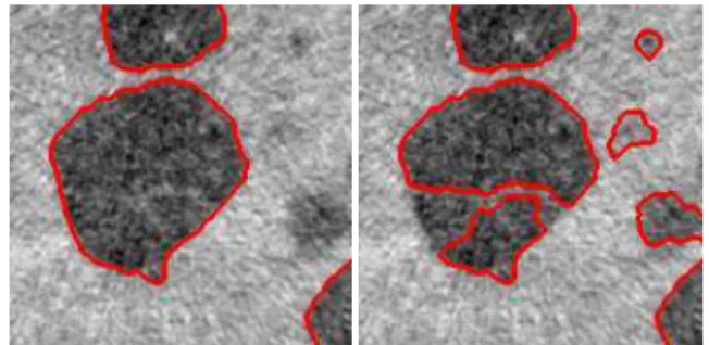
Problems with the swamping segmentation: Two major problems appear (Fig. 6):
– The property of inclusion is not satisfied because the final partition of large grains includes some small grains.
– The phase of individualization of each grain with a single marker can be obtained with the addition of some wrong markers that are not located in the grains.
Fig. 6. One wrong region in the center and
multi-inclusion of small grains
Marker pyramid:
– Let(G1, . . . , Gn), the different set of grains (in the case of material B there are two sets(Gs, Gl)).
– Let(M1, . . . , Mn), the set of markers such as each Mi satisfies the property of individualization for the grains Gi.
The problem of the obtained partition SMl is that
some small grains are included: ∃g ∈ Gs/g ⊂ S
Ml .
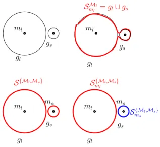
To avoid this major problem, a marker pyramid was developed. The partition of each set of grains Gj is: PMj m = S S iMi−δ SSiMi,∞( [ i6= j Mi) , (10)
such asδX,λ(Y ) is the geodesic dilatation of sizeλof Y in X . To prevent from the inclusion of small grains, the markers of small grains were added to the swamping segmentation SSiMi. The subtraction of the geodesic
dilatation of size∞ofSi6= jMiin SSiMi, removes all
the areas not included in Gj (Fig. 7).
ml gs gl ms ml ml gs gs ms gl ml gs gl S{Ml,Ms} ms S{Ml,Ms} S{Ml,Ms} ml gl SMl ml = gl∪ gs
Fig. 7. The up and left picture shows two grains and
markers: small and large. The up and right picture shows the inclusion of a small grain. The down picture shows the result of the marker pyramid.
The result (Fig. 8) shows that the inclusion problem is now solved. In the next step, the wrong grains must be removed.
Fig. 8. First problem resolved: inclusion problem
CLASSIFICATION OF MARKERS
The problem of virtual or wrong grains comes from the addition of markers outside of the grains. The first idea is to filter the set of markers and to keep only the right ones. But the problem is how to characterize a right or a wrong marker, when a marker represents only some voxels. For this reason, the classification between right or wrong grains was performed at the end of the segmentation Fricout (2004).
The classification criterion uses the tint information. The approach consists of selecting a grey-level range. This range corresponds to the tint of the grain class that we want to extract. A numerical grain is erased if less than half of its voxels are in this range. It is considered as artefacts. For the material A, the range is 70-140 for the big grains (see Fig. 9).
TARIELVET AL: Multi-scale segmentation
Fig. 9. First image: the 3D mesh on a segmented image
of material B. Second image: a slice of the segmented image. The red lines represent the numerical grains boundary and match the visual segmentation.
RESULTS
After segmentation, of the grains, it is possible to use a meshing procedure of the boundary of the grains in the 3D space (Fig. 10). Then, the meshed image can be introduced in a finite elements code to compute stresses and strains, as well as other fields like the thermal flux and the temperature distribution in the material at a micro scale. These calculations are a first step to predict the macroscopic behavior of the granular pyrotechnic materials, and will then help us to improve their safety and performances
Fig. 10. Example of 3D mesh on a segmented image of
a granular material.
CONCLUSION
Microtomographic images involve specific problems of image segmentation, due to some artefacts generated during the reconstruction. In the case of granular materials, we have seen that many problems can appear during the usual swamping segmentation. In the first part of this paper, the Pyramid Union was introduced to solve the problem of individualization of each grain with a single marker, under the assumption that all markers and associated boundaries are included in the grains. In the second part, the false detection of wrong grains was removed by means of a classification of markers; the wrong inclusion of small grains in large grains is solved by adding markers from a lower scale, based on a Marker Pyramid. Therefore a multiscale approach of watershed segmentation, necessary for microstructures involving a wide range of scales, enables us to improve a segmentation, that it would be difficult to obtain by other means.
REFERENCES
Beucher S (1990). Th`ese: Segmentation d’images et morphologie math´ematique. Paris: Ecole des Mines de Paris.
Beucher S, Meyer F (1990). Morphological segmentation. J Vis Commun Image R 1(1):21–46.
Buffiere J, Maire J-Y, Merle E (2000) X-Ray Tomography in Material Science. Paris: Hermes Science Publications. Fricout G (2004). Th`ese: Propri´et´es Morphologiques et
optique des surfaces rugueuses. Paris: Ecole des Mines de Paris.
Kanit T, N’Guyen F, Forest S, Jeulin D, Reed M, Singleton S (2006). Apparent and effective physical properties of heterogeneous materials: representativity of samples of two materials from food industry. Comput Meth Appl Mech 195(33-36):3960–82.
Serra J (1982). Image Analysis and Mathematical Morphology, vol. I. London: Academic Press, .
Serra J, ed. (1988). Image Analysis and Mathematical Morphology. Vol. II, Theorical advances. London: Academic Press.