HAL Id: cea-02339873
https://hal-cea.archives-ouvertes.fr/cea-02339873
Submitted on 5 Nov 2019
HAL is a multi-disciplinary open access
archive for the deposit and dissemination of
sci-entific research documents, whether they are
pub-lished or not. The documents may come from
teaching and research institutions in France or
abroad, or from public or private research centers.
L’archive ouverte pluridisciplinaire HAL, est
destinée au dépôt et à la diffusion de documents
scientifiques de niveau recherche, publiés ou non,
émanant des établissements d’enseignement et de
recherche français ou étrangers, des laboratoires
publics ou privés.
Effect of dislocation channeling on void growth to
coalescence in FCC crystals
P.O. Barrioz, J. Hure, B. Tanguy
To cite this version:
P.O. Barrioz, J. Hure, B. Tanguy. Effect of dislocation channeling on void growth to coalescence in
FCC crystals. Materials Science and Engineering A- Structural Materials Properties Microstructure
and Processing, Elsevier, 2019, A749, pp.255-270. �10.1016/j.msea.2019.01.115�. �cea-02339873�
E
ffect of dislocation channeling on void growth to coalescence in FCC crystals
P.O. Barrioz, J. Hure∗, B. TanguyaCEA Saclay, Universit´e Paris-Saclay, DEN, Service d’ ´Etudes des Mat´eriaux Irradi´es, 91191 Gif-sur-Yvette, France
Abstract
The effect of dislocation channeling - a heterogeneous deformation mode at the grain scale observed in irradiated, quenched or heavily cold-worked materials - on void growth to coalescence in Face-Centered-Cubic (FCC) crystals is investigated exper-imentally. Solution Annealed 304L austenitic stainless steel is used as a model FCC material, in a reference state or irradiated with protons in order to trigger dislocation channeling deformation mode. Micrometric cylindrical voids drilled using Focused Ion Beam (FIB) technique at the grain scale in thin tensile samples subjected to uniaxial stress loading conditions allows a detailed description of void growth and coalescence. Compared to the reference state where plasticity appears homogeneous at the void scale, dislocation channels strongly interact with voids at the irradiated state, especially at low applied strain where characteristic localization patterns are observed and described. As applied strain increases, deformation becomes more and more homogeneous at the void scale through gradual activation of secondary channels. Numerical simulations based on FCC crystal plasticity con-stitutive equations are performed and compared to experiments. The main experimental features are recovered by the numerical simulations, but discrepancies remain for both reference and irradiated states. Ductile fracture modeling in materials exhibiting dislocation channeling is finally discussed based on these experimental and numerical results.
Keywords: Ductile fracture, Void growth, Coalescence, Dislocation channeling, Irradiation
1. Introduction
Ductile fracture through void growth to coalescence is a common failure mode of metal alloys [1] which involves three different stages known as void nucleation, growth and coales-cence [2, 3]. Inclusions or second-phase particles debonding or
5
cracking [4] lead to voids that grow under diffuse plastic flow [5, 6] until coalescence occurs through localized plastic flow between adjacent voids [7, 8]. Early models [6] have empha-sized the major roles played by porosity - void volume fraction - and stress triaxiality - ratio of hydrostatic stress over
devia-10
toric stress - on ductile fracture through void growth to coa-lescence, but also the effect of the mechanical behavior of the matrix material surrounding the voids through the hardening modulus [5]. The critical influence of matrix material behav-ior has been subsequently detailed mainly through porous
unit-15
cells simulations, where both plastic anisotropy (i.e. through Hill’s yield criterion) (see [9, 10, 11] and references therein) and strain-hardening effects [12, 13] were confirmed. Specific directions of the porous material appear harder or softer due to plastic anisotropy, while void growth in materials
exhibit-20
ing strong strain-hardening may be significantly diminished, as shown also experimentally in [14] and [15]. Early examina-tions of fracture surfaces characterized by dimples or recent X-ray tomography visualization [16] show that, for many metal alloys, voids involved in ductile fracture have often a size well
25
below the grain size, i.e., voids are in single crystals. In that case, the existence of well-defined sets of slip systems may
∗Corresponding author
lead to a very strong plastic anisotropy that has been shown to influence void growth. Analytical [17] and experimental re-sults [18, 19] showed the interactions between crystallographic
30
orientations and void shapes as well as lattice rotations around voids. Full three-dimensional porous unit-cells simulations us-ing crystal plasticity constitutive equations for the matrix mate-rial [20, 21, 22, 23] emphasized the influence of crystal orien-tation and void arrangement on void growth and coalescence,
35
especially for low stress triaxialities. All these experimental and numerical results serve as a basis to the development of homogenized models for porous materials incorporating the ef-fects of porosity, stress triaxiality, matrix anisotropy and hard-ening ([24, 25] for recent reviews) following early works of
40
Gurson [26] and Thomason [27]. The most advanced contri-butions include the combined effects of void shapes and crystal plasticity for voids in single crystals [28, 29, 30].
Homogenized models for porous materials described here-above consider that the matrix material around voids deforms
45
rather homogeneously at the void scale. Such assumption comes from the choice of matrix material constitutive equations that do not exhibit softening, which is a necessary condition for strain localization to happen [31]. However, lower scale simu-lations such as Discrete Dislocations Dynamics (DDD) clearly
50
indicate that heterogeneous dislocations structures do appear at void scale [32, 33, 34]. Finite element porous unit-cell simula-tions using softening matrix material [35] also show heteroge-neous deformation through localization bands and their inter-actions with void growth. Materials exhibiting highly
hetero-55
geneous deformation mode at the grain scale through the ap-pearance of localization bands are in fact not so uncommon,
such as irradiated or quenched materials [36, 37]. Such phe-nomenon, referred to as dislocation channeling, is particularly observed and studied in irradiated metal alloys. Irradiation with
60
high-energy particles, e.g., encountered in nuclear power plants, leads to the creation of crystalline defects such as dislocations, dislocation loops, nano-voids and precipitates in metallic ma-terials [38, 39] through ballistic interactions between incident particles and atoms. In addition to drastic evolution of
macro-65
scopic mechanical properties [40, 41, 42], the presence of these nano-scale defects can induce a change of deformation mecha-nisms at the grain scale where plasticity is observed to be con-fined into narrow channels surrounded by undeformed material [43, 44]. From a metallurgical point of view, dislocation
chan-70
neling is explained by the removal of immobile irradiation fects by a leading dislocation, creating a clear path (free of de-fects) where following dislocations can easily glide [45, 46, 47]. From a mechanical point of view, the potential removal of irra-diation defects corresponds to a softening mechanism that can
75
trigger strain localization. An example of the manifestation of dislocation channeling is given in Fig. 1a, where widely spaced slip traces can be observed at the surface of an irradiated ma-terial under mechanical loading. Dislocation channeling defor-mation mode has consequences on the macroscopic
mechani-80
cal properties of irradiated materials, such as limited hardening that favors macroscopic plastic instability [46] and a potential detrimental role in intergranular stress-corrosion cracking due to high stresses arising at the intersection between channels and grain boundaries [48]. Dislocation channeling is not limited
85
to irradiated materials, but has also been observed in quenched [49, 50] or predeformed [51] materials. The mechanism is sim-ilar to the case of irradiated materials, where defects that can be removed are created due to quenching or prestraining.
(a) (b)
Figure 1: (a) Slip traces observed at the surface of a sample of irradiated austenitic stainless steel subjected to uniaxial stress loading conditions (taken from [52]), resulting from dislocation channeling deformation mode. (b) Sketch of the potential influence of dislocation channeling on void growth to coales-cence mechanism
Recent experimental observations [53, 54, 55], numerical
90
simulations [56, 57, 58] and analytical models [59] lead to a better understanding of channels initiation mechanisms, widths and spacings. However, the potential influence of dislocation channeling on micron-scale void growth to coalescence has not been studied (Fig. 1b), although ductile fracture is the
domi-95
nant fracture mode of materials exhibiting dislocation channel-ing (e.g. irradiated austenitic stainless steels [60]). Therefore,
the main objective of this study is to investigate experimentally the influence of dislocation channeling on micron-scale void growth to coalescence fracture mechanism. In addition,
numer-100
ical simulations based on crystal plasticity constitutive equa-tions are performed and compared to experimental results. In order to amplify the potential effects, void deformation under low applied stress triaxiality (where crystal anisotropy effects are known to be more significant) in highly irradiated material
105
(where severe dislocation channeling is expected) are used in the following and compared to a reference (unirradiated) case where homogeneous deformation mode occurs.
The paper is organized as follows. In Section 2, the mate-rial and methods used are described, with an emphasis on the
110
experimental setup allowing assessing void growth to coales-cence in crystals and on obtaining a material exhibiting dislo-cation channeling deformation mode through irradiation. Sec-tion 3 describes the experimental results, comparing the effect of homogeneous vs. heterogeneous plasticity on void
deforma-115
tion as a function of applied plastic strain. Experimental results are discussed with respect to ductile fracture modeling in mate-rials exhibiting dislocation channeling in Section 4, as well as compared to numerical results.
2. Material and Methods
120
In this section, the material and the methodology used in this study to assess experimentally the effect of dislocation chan-neling on void growth to coalescence in FCC crystals is de-tailed. In addition, the numerical method and constitutive equa-tions used to model FCC single crystals are described.
125
2.1. Material
A commercial austenitic stainless steel of type 304L has been selected for this study. 304L has a Face-Centered-Cubic (FCC) crystallographic structure, and thus can serve as a model alloy to describe other FCC materials where dislocation
chan-130
neling is observed. Moreover, austenitic stainless steels have been thoroughly characterized with respect to the evolution of the mechanical properties [61] as well as deformation mecha-nisms [62, 44] with irradiation, and exhibit dislocation channel-ing after irradiation when tested at high temperature (300◦C).
135
Pb W Zr S P C Mg Co Si
8ppm 0,035 12ppm 0,002 0,010 0,012 0.003 <0,05 0.450
Cu V Mo Mn Ti Ni Cr Fe
0,240 0,015 0,020 1,650 <0,05 8,55 18,75 Bal
Table 1: Chemical composition (in weight %) of 304L austenitic stainless steel
304L is a material used for most parts of Light Water Reactors (LWR) internal structures [42], so that results obtained in this study will be relevant regarding industrial issues. The chemical composition of the material is given in Tab. 1.
(a) (b)
Figure 2: Electron Back-Scattered Diffraction (EBSD) analysis of the material, (a) in the as-received state and (b) after additional heat-treatment (4 hours at 1100◦C followed by water quenching). Colors correspond to different crys-tallographic orientations. Heat treatment allows to make grains bigger and to reduce the number of small grains
The material was supplied in a solution annealed condition (Heat treatment of 30 minutes at 1100◦C followed by water quenching). The methodology described in Section. 2.2 requir-ing large grain size, an additional heat treatment of 4 hours at 1100◦C followed by water quenching was performed on plates
145
(90x100x3mm) to obtain larger grains. Typical crystallographic structures obtained by Electron Back-Scattered Diffraction (EBSD) on the as-received material and after the additional heat treat-ment are given Fig. 2. The evolution of grain diameter distribu-tion after the addidistribu-tional heat treatment shows a slight mean
in-150
crease of 8µm, but large grains in the as-received condition have grown significantly (up to 200µm diameter). Hereafter, the (ref-erence) material refers to the one with the additional heat treat-ment. The Vickers hardness was measured to be 193±10 HV0.02
using conventional Vickers micro-hardness machine with 20g
155
applied load and 10 seconds hold time. Tensile specimens of gage length 8mm, width 2mm and thickness 2mm were ma-chined through electrical discharge machining. Tensile tests have been performed at 300◦C on an universal testing machine, and stress-strain curve is given on Fig. 3.
160
Solution-Annealed 304 austenitic stainless steel is known to deform rather homogeneously at the grain scale through dislo-cation glide in high temperature testing (300◦C) [44], and will
thus serve as a reference state to assess the effect of dislocation channeling on void growth. In order to get a material that has a
165
dislocation channeling deformation mechanism, part of the ten-sile samples from the reference material were irradiated with high energy protons. An irradiation energy of 2MeV was se-lected in order to have a significant irradiated thickness, while the fluence (H+.cm−2) and irradiation temperature were
cho-170
sen in accordance to previous studies [52] so to have signifi-cant irradiation defects to trigger dislocation channeling. Prior to irradiation, tensile samples were mirror polished using stan-dard polishing techniques up to 1/4µm diamond paste. 2 MeV proton irradiation was performed at 350◦C ± 10◦C on tensile
175
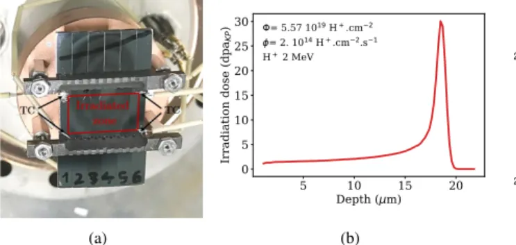
samples using Tandem accelerator at Michigan Ion Beam Lab-oratory, University of Michigan [63]. The integrated fluence is 5.57 1019 H+.cm−2 with a flux about 2 1014 H+.cm−2.s−1.
Temperature was controlled by an infrared camera and using 4 thermocouple probes (Fig. 4a) welded on the tensile samples
180
and calibrated prior to irradiation. As discussed in [64], these conditions lead to irradiation defects in quantitative agreement (number, size) with the ones observed for neutron irradiation at about 290◦C, so that the irradiated material obtained in this
study is relevant for Light Water Reactors conditions.
Irradi-185
ation levels are usually characterized with Displacements Per Atoms (noted dpa) value that attempts to compute the average value an atom from the material has been displaced from its lat-tice position during the irradiation. Such value is particularly relevant when comparing irradiations with different particles
190
(neutrons, ions, electrons). SRIM-2013 software [65] was used to compute dpa, using Kinchin-Pease (KP) model [66] and a displacement energy of 40 eV for Fe, Cr and Ni [67]. The dam-age profile is given in Fig. 4b, showing an irradiated layer of about 18µm depth. As shown in [52], for these irradiation
lev-195
els, dislocation channeling is expected under mechanical load-ing at 300◦C. The irradiated microstructure constituted mainly
of Frank dislocation loops has been fully characterized, and re-sults are detailed in Appendix A.
0
2
4
6
8 10 12
Cumulative plastic strain %
0
100
200
300
400
500
Cauchy stress (MPa)
Thin sample Bulk sample Simulation
Figure 3: Tensile curves - Cauchy stress as a function of cumulated plastic strain - for the reference material (as-received with additional heat treatment). Exper-imental results on a thick tensile sample (Bulk sample) and thin tensile sample (Thin sample, see Section 3). Numerical result using a polycrystalline Voronoi aggregate and FCC crystal plasticity constitutive equations (Section 2.2).
2.2. Methods
200
2.2.1. Experimental methodology
The experimental methodology used to assess void growth and coalescence is derived from the one proposed by Weck & Wilkinson [68] based on model cylindrical holes obtained through laser machining in thin tensile samples. Upon
strain-205
ing, monitoring voids shapes evolutions with Scanning Electron Microscope (SEM) as a function of applied strain allows to as-sess the physical mechanisms involved as well as to evaluate models, as still done recently in [69].
Substantial modifications of the original setup are required
210
to assess void growth in single crystals exhibiting dislocation channeling deformation mode. Firstly, as described in Sec-tion 2.1, the maximal depth of the irradiated layer is about 20µm
(a) 5 10 15 20 Depth ( m) 0 5 10 15 20 25 30 Irr ad iat io n do se (d paKP ) = 2. 10= 5.57 1014 H+.cm2.s1 19 H+.cm2 H+ 2 MeV (b)
Figure 4: (a) Irradiation setup: Tensile samples are mounted on a copper stage cooled by liquid nitrogen to compensate heating due to high flux proton irradi-ation. Details about the irradiation setup can be found in [63] (b) Dose in dpa as a function of depth through the thickness of the 304L samples. Dpa level is computed using SRIM-2013 software [65], using Kinchin-Pease (KP) model, with a displacement energy of 40 eV.
- with an almost constant irradiation dose thickness of about 15µm - so that tensile samples used should be thinned down
215
to less than 20µm to get an almost homogeneous sample ex-hibiting dislocation channeling. This thickness also ensures to get a polycrystalline material with mostly one grain across the thickness - at least for large ones - due to the grain growth heat treatment applied (Section 2.1). Tensile samples are thinned
220
down to less than 20 µm by mechanical polishing: SiC grinding paper is used with grit of 320 up to 200 µm thickness, then 600 grit up to 100 µm and 1200 grit until the final thickness. The thickness of the samples is regularly measured with a dial in-dicator to verify the good parallelism of the samples faces, and
225
finally precisely measured in SEM.
Secondly, as irradiation was performed before drilling the cylindrical holes, laser machining technique has been replaced by another technique, as laser induces local heating that might remove close to the holes the irradiation defects needed to get
230
dislocation channeling mechanism. Focused-Ion Beam (FIB) machining was selected as it does not involve any heating, and generates artefacts (additional irradiation defects) only in very limited regions (. 100nm). On one face of the sample, an elec-trochemical attack (using 60% volume nitric acid at 65%, 40%
235
volume water) is first performed to reveal grain boundaries and to select large grains. EBSD analysis is also performed all along the gauge surface to assess crystallographic orientations. Cylin-drical voids (either one or two) are then drilled using FIB in sin-gle grains throughout the thickness of the tensile samples. FIB
240
milling leads to slightly conical through-thickness void shape that is minimized by performing drilling on both sides of the specimens. Void diameter, selected as the smallest allowing drilling completely through the thickness of the thin samples, remains however slightly smaller in the middle of the specimen
245
than on the surface. For the reference material (resp. irradi-ated), voids mean diameter is 11.0 µm (resp. 4 µm), with inter-void distance of 15 µm (resp. 7.5 µm) when two adjacent inter-voids are drilled.
In addition, in order to get full-field strain measurements
250
through high resolution Digital Image Correlation (DIC), a speckle pattern is generated on the other face of the sample by the
re-modeling of a deposited gold layer using the methodology de-veloped in [70]. Surface is polished up to 1/4 µm diamond paste and then polished during 10 min with a colloidal silica solution
255
(0.05µm, pH=7). A 70 nm gold layer is deposited using a stan-dard metallizer. Finally, the gold film is remodeled during 1h at 300◦C under water vapor leading to a speckle pattern with
speckles size from 100 to 200 nm (see Inset Fig. 7b).
This methodology, described schematically in Fig. 5, allows
260
to get thin tensile samples with model cylindrical holes in FCC crystals, for both reference material that have homogeneous de-formation mode at the grain scale and irradiated material having dislocation channeling deformation mode. For the latter, as the material is expected to exhibit early macroscopic necking due
265
to limited strain-hardening capability, notches have also been drilled using FIB at locations where voids have been drilled, in order to ensure that plasticity will take place in that area (Fig. 10b).
Figure 5: Overview of the different steps of samples preparation: mirror pol-ishing, irradiation, thinning of bulk samples by mechanical polishing leading to fully irradiated 2D polycrystalline aggregate (with one grain along the thick-ness), FIB drilling of cylindrical holes in grains.
Tensile tests are performed on an in-situ SEM micro
me-270
chanical tensile machine equipped with a 200N load cell at a mean strain rate of 10−4s−1. A resistive heater in direct con-tact with the back of the specimen allows heating to a target temperature of 300◦C. Because of the extreme thickness of the samples, temperature is not measured during the tensile tests.
275
Tests are performed previously to calibrate the temperature of the resistive heater to have a temperature of 300◦C on the thin sample (measured with a thermocouple). The uncertainty on the temperature value is estimated to be ± 25◦C. Interrupted tensile tests are performed to monitor the evolution of voids
280
shapes as a function of applied strain. For each (pair of) void in the reference material, SEM acquisitions are performed us-ing back-scattered electrons mode signal with a resolution of 2048x1536 pixels. The magnification is x2000. The contrast is maximized while limiting the noise in order to facilitate the
285
digital image correlation. For the irradiated material, acquisi-tions are performed using secondary electrons mode signal with a resolution of 3072x2304 pixels.
2.2.2. Numerical methods
Digital image correlation is performed using Yadics
soft-290
ware [71] with the finite element method (8x8 subdivision pixel is used and 5x5 median filter). Results are plotted with a 2D equivalent strain defined as: εeq= [2/3]qε2xx+ ε2yy+ 2ε2xy.
Numerical simulations of the experiments are performed us-ing crystal plasticity models and Fast Fourier Transform(FFT) based solver AMITEX FFTP [72]. Details about these simu-lations can be found in Appendix B so that only the modeling of the mechanical behavior of the material and boundary condi-tions are described in this section. Simulacondi-tions relie on crystal plasticity constitutive equations that are widely used in the liter-ature to describe single crystals in structural calculations [73], accounting for the existence of slip systems that are activated once the resolved shear stress on a given slip system exceeds a critical value. In a viscoplastic version of crystal plasticity, the flow rule is:
. γs =* |τs| −τsc K +n +
sign(τs), with h•i+=( • ; • > 0 0 ; • ≤ 0 (1) where γs and τs = σ : Ns are the shear strain and resolved shear stress in slip system s, respectively, with Ns= ms⊗ nsthe
Schmid tensor characterizing a slip system of normal ns and
direction ms. Parameters K and n regulate the viscosity of the
plastic flow, and are usually used only for numerical purposes close to the rate independent limit. τs
ccorresponds to the critical
resolved shear stress that evolves with shear strain, thus mod-eling strain-hardening. For the reference material, physically-based hardening for austenitic stainless steels described in [74] is used. The critical resolved shear stress is written:
τs c= τ0+ µ s X u asuru r.s= qP s bsuru κ − Gcrs |γ.s| (2) where rs is the normalized dislocation density in the slip sys-tem s and asuis a 12x12 matrix with 6 independent parameters
295
which characterize the long-range interactions between dislo-cations. The evolution of dislocations in slip systems is com-posed by a multiplicative and an annihilation terms. bsu is an
interaction matrix with the same shape of asu. κ is proportional
to the number of obstacles crossed by a dislocation before
be-300
ing immobilized and Gc depends on the annihilation
mecha-nisms of dislocations. Parameters of the law are taken from [74], except three parameters (τ0, κ and Gc) that have been
obtained through calibration of the tensile response of a 3D polycrystalline Voronoi aggregate against experimental tensile
305
curve from a bulk sample - similarly to what have been done in [75] - leading to: {τ0= 70 MPa, κ = 10 , Gc= 12}. The
com-parison between the experimental and numerical tensile curves is given in Fig. 3.
For the material where dislocation channeling is expected, crystal plasticity constitutive equations have been proposed in the literature to describe the presence of removable irradiation defects [75, 76, 77], leading to locally softening behavior and to the appearance of localization bands. These models involve many additional state variables / parameters and are numeri-cally heavy. Thus, a simple phenomenological softening law (Eq. 3) is used. Slip systems are considered independent to each other as a first approximation. The second term of Eq. 3 aims at modeling softening induced by the removal of irradiation de-fects. At large strains, re-hardening is expected due to multipli-cation of dislomultipli-cations, corresponding to the third term added in
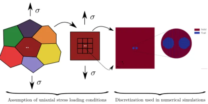
Figure 6: Assumption of uniaxial stress loading conditions at the grain scale used in the numerical simulations, by considering either static uniform bound-ary conditions or periodic boundbound-ary conditions (Appendix B)
Eq. 3. In all simulations reported hereafter, the values of the pa-rameters are set to (τ0 = 100 MPa, ∆τ1 = 50 MPa, γ0 = 0.01),
but have no influence on localization patterns reported in Sec-tion 4. The parameter∆τ2is set equal to∆τ1or zero to assess
the effect of rehardening.
τs c= τ0+ ∆τ1 exp − γs γ0 +∆τ2 γ0 |γs−γ0| (3)
In order to be able to perform numerical simulations only
310
at the single grain scale where the voids are drilled, an assump-tion has to be made regarding the stress/strain state of a single grain inside a 2D polycrystalline aggregate subjected to uniax-ial stress loading conditions. Low constraint along the thick-ness leads to assume that uniaxial stress conditions also applies
315
at the grain scale. A unit cell containing (one or) two cylindri-cal voids is thus considered, as shown on Fig. 6. Uniaxial stress state can be applied either considering static uniform boundary conditions either assuming periodic boundary conditions. Both conditions can be applied through FFT based simulations, as
320
shown in Appendix B, where the latter is a standard loading condition while the former can be made adding free surfaces at the cell boundaries. The choice between these two boundary conditions is detailed and discussed in Section 4.
3. Experimental results
325
3.1. Homogeneous deformation mode
Interrupted tensile test has been performed on the reference material tensile sample of thickness ∼ 15µm, with seven strain increments, the last one corresponding to fracture of the sam-ple. After each increment, applied load was kept constant
dur-330
ing the acquisition of SEM images of the voids. The tensile curve obtained with the thin sample is given on Fig. 3. Com-pared to the tensile curve of the reference material obtained on a bulk sample, higher stress is measured for the thin sample, which was suspected to come from a hardened layer induced by
335
the mechanical polishing. Transmission Electron Microscope (TEM) investigation (not shown here) revealed a higher dislo-cation density than a typical solution annealed state under the surface, at least to a depth of 7 µm (which corresponds to the
(a) (b)
Figure 7: (a) Evolution of voids shapes as a function of macroscopic plastic strain inside a grain with crystallographic orientation [106◦, 156◦, 207◦] (Euler angles orientation with the Bunge convention (zx'z'') obtained through EBSD on the other side of the sample (Fig. 5)). Tensile direction is along x (b) Digital image correlation on voids V1 between the images taken at 1.4% and 2.3% macroscopic plastic strains. Inset: Initial speckle pattern
depth of the TEM sample). The average hardening (across the
340
thickness) due to mechanical polishing corresponds to a pre-strain of about 4% (Fig. 3). However, such pre-pre-strain is not ex-pected to influence void evolution as a function of applied strain as the macroscopic strain-hardening modulus - which is a key parameter [14] - is rather constant in that range of deformation.
345
Figure 7a shows the typical evolution of two voids under mechanical loading. Voids elongate along the tensile direction, and shrink along the perpendicular direction, as expected from such low stress triaxiality conditions [68]. Due to premature failure of the tensile sample (which is expected for such thin
350
samples that are known to be sensitive to machining imperfec-tions), no coalescence events have been observed. As deforma-tion increases, lines can be seen on the images that correspond to steps on the tensile specimen surface. These steps are the traces of activated slip systems that have a slip direction with a
355
non-zero component along the normal direction of the samples, thus leading to an extrusion which are well captured with SEM images sensitive to topology changes. On that particular case, only one slip system appears to be activated. As a slip system with slip direction perpendicular to the sample normal would
360
not lead to steps - thus being invisible with SEM images - digi-tal image correlation has been performed to assess the potential activation of secondary slip systems. Fig. 7b shows a typical example of strain field obtained where no clear indication of activation of other slip systems can be found. Thus, a single
365
slip state occurs, consistently with the uniaxial stress loading conditions associated with non-symmetric crystallographic ori-entation. Voids are found to have no clear influence on plastic-ity as slip bands have similar orientations far and close to the voids. Similar observations were also done in [78] on voids in
370
an aluminum alloy where plastic slip traces appear to run across the voids.
Analysis of other void shapes evolutions on the same ten-sile sample but in different grains leads mainly to the same con-clusions. In all cases, crystallographic orientations are, as in
375
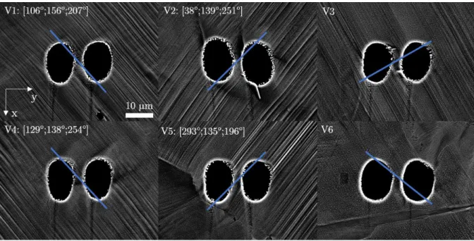
the first case, non-symmetric with respect to the loading direc-tion. Fig. 8 shows the different sets of voids for a given
ap-plied macroscopic strain, which are very similar qualitatively to what have been already discussed based on Fig. 7 for voids denoted V1, V2, V3 and V4. For voids V5 and V6, slip lines
380
patterns suggest the presence of grain boundaries close to the voids which complicates the analysis. As almost uniaxial stress state is expected at the grain scale especially due to the presence of only one grain along the thickness (Fig. 5), the computation of the highest Schmid factor S (defined such as τs= S σ) is
ex-385
pected to find the active slip system. This is confirmed on Fig. 8 where slip traces of the slip system with the highest Schmid fac-tor match well with the slip traces observed for voids V1, V2, V4 and V5. This also confirms that, for these voids, there is only one grain along the thickness as EBSD measurements
-390
used to compute crystallographic orientations and thus Schmid factors - have been performed on the other side of the specimen (Fig. 5). For voids V3 and V6, no agreement is observed, proba-bly related to the presence of several grains along the thickness, so that the orientations reported on Fig. 8 may not describe the
395
crystal throughout the thickness.
Quantitatively, the evolution of voids axis a and b (defined as the axis of an ellipse inscribed in the voids Fig. 7, averaged on the two voids) as a function of engineering plastic strain (de-noted Fxx− 1= ∆l/l0, with l0the initial gage lenth of the
ten-400
sile sample, and∆l the elongation) measured from the tensile curve are plotted on Fig. 9. Even though voids deformation ap-pears qualitatively similar, as shown in Fig. 8, significant di ffer-ences are observed due to crystallographic effects, which have been shown to be predominant for void shape evolution
un-405
der low stress triaxialities conditions in numerical simulations [33, 79, 80, 81]. Differences of void elongation along the tensile direction up to 100% are found, e.g. between voids V1 and V2. Experimental results on voids evolutions in the reference mate-rial, that exhibits very homogeneous deformation mode, serve
410
as a reference case to be compared to similar results described in the next section in presence of dislocation channeling.
3.2. Dislocation channeling deformation mode
As for the reference material exhibiting homogeneous de-formation mode, interrupted tensile tests have been performed
Figure 8: Comparison of the voids shapes for 6 different pairs of voids at 12.7% macroscopic plastic strain on the reference material sample. Tensile direction is along x. Euler angle orientations of the grains, given with the Bunge convention [zx'z'']), are obtained by EBSD analysis on the other side of the sample (Fig. 5). Blue line is the intersection between the surface and the slip plane of the slip system having the highest Schmid factor calculated assuming uniaxial stress state and computed on the undeformed configuration.
Figure 9: Evolution of voids axis a and b (defined as the axis of an ellipse inscribed in the voids, see Fig. 7) as a function of engineering plastic strain (denoted Fxx− 1= ∆l/l0, with l0the initial gage lenth of the tensile sample, and∆l the elongation) for the reference material
on the irradiated thin tensile samples - expected to have disloca-tion channeling deformadisloca-tion mode. The only difference is that notches have been drilled on the tensile samples (Fig. 10b) to macroscopically localize deformation in the region where voids have been drilled, as early necking of such material is expected.
420
Average applied strain along the tensile direction applied to the voids can not be computed from the tensile curve, contrary to the reference material. Moreover, in case where deformation is not homogeneous, any measure of strain is dependent on the reference length on which it is computed. Thus average strain
425
levels along the tensile direction (along the x axis) are eval-uated using displacements measured at the boundaries of the
images taken of voids shapes and reference length equal to the images’ height (Fig. 10a), for comparisons purposes to the ref-erence material.
430
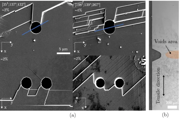
Figure 10 shows typical results at the early stages of voids deformations, corresponding to very low applied strain on the tensile sample. Highly localized deformation mode is observed with plasticity localized into few channels, leading to steps on the sample surface. Transmission Electron Microscopy (TEM)
435
observations shown in Appendix C confirm that these channels correspond to regions where irradiation defects have been re-moved, thus to dislocation channeling deformation mode. Strong interactions between dislocation channels and voids are observed. A typical pattern (Fig. 10a left images) is the activation of two
440
different slip systems. One of them (indicated by the blue line) has the highest Schmid factor under the assumption of uniaxial stress state (as for the reference material), and the associated channel crosses almost the entire grain. The other activated slip system has a low Schmid factor, but has the particularity
445
to have a slip direction belonging to the slip plane of the other slip system. These features are recurrent in all situations ob-served at low applied macroscopic strain, and will be discussed in Section 4. It was not possible to characterize nucleation and propagation of these channels. As a consequence of
disloca-450
tion channeling, void growth is discontinuous, and potentially severe considering the very low level of macroscopic applied strain. The distance between slip traces tends to be closer as the deformation increases. Figure 11 shows voids in the coa-lescence regime for two different pairs of voids. Distance
be-455
tween slip traces is very low compared to the distance far from the voids. Voids shape after coalescence tends to be similar to what is typically observed in materials deforming homoge-neously [68, 82]. At the very end of one test (Fig. 11a), a crack
Figure 10: (a) Characteristic slip patterns around voids in material exhibiting dislocation channeling deformation mode. Each image corresponds to different grains: Euler angle orientation (given with the Bunge convention [zx'z'']) are obtained by EBSD analysis on the other side of the sample. Average strain levels along the tensile direction (along the x axis) are evaluated using displacements measured at the boundaries of the images and a reference length equals to the images’ height. Blue line is the intersection between the surface and the slip plane of the slip system having the highest Schmid factor calculated assuming uniaxial stress state and computed on the undeformed configuration. (b) Visualisation of half of the irradiated thin tensile sample, showing the area where voids have been drilled and notch geometry used to localize plasticity.
that initiates from the sample notch propagates towards the
re-460
gion where voids were drilled. The particular shape of the voids for 35% strain is attributed to the crack coming across the voids. Experimental results indicate a strong effect of dislocation channeling deformation mode on voids evolution in single grains subjected to uniaxial stress conditions. A clear interaction
be-465
tween dislocation channels and voids is observed through the appearance of characteristic deformation patterns. As applied strain increases, additional channels are activated, leading to more homogeneous deformation mode. Upon coalescence -that corresponds to interactions between adjacent voids and thus
470
to deviation from uniaxial stress loading conditions between the voids and higher local strains - the effect of dislocation channel-ing on voids evolutions weakens. These results are discussed in the next section with respect to ductile fracture modeling through void growth to coalescence in material exhibiting
dis-475
location channeling deformation mode, as well as compared to numerical simulations.
4. Discussion
4.1. From dislocation channeling to homogeneous deformation For low applied strain, a clear difference regarding voids
480
evolution has been observed between the reference material that
has an homogeneous deformation mode and the irradiated ma-terial having a dislocation channeling mode. For the latter case, a characteristic dislocation channels pattern has been observed where two slip systems are activated. In most situations (where
485
there is only one grain through the thickness), the pattern ob-served on one side corresponds to point symmetry to the one observed on the other side where the homothetic center appears to be close to the middle of the sample, at the center of the void (or at the middle of the intervoid line for the cases with two
490
voids). In addition, another interesting feature is that the chan-nels corresponding to the slip system with the highest Schmid factor (Fig. 11a) are often observed at some distance δ from the voids, typically on the order of void diameter. These observa-tions can be rationalized as follows. Assuming that the primary
495
activated slip system is the one with the highest Schmid factor in uniaxial stress conditions, the slip plane normal is oriented at about 45◦ from the loading direction, defining a family of
potential slip planes as sketched in Fig. 12. The intersections between these planes and the sample surfaces correspond to the
500
steps observed in the experiments, which are related through a point symmetry from one side to the other. The position of the homothetic center can be understood as follows. For a voided plate subjected to a far field uniaxial tension state, local stresses
Figure 11: Typical observations of voids coalescence in the material exhibiting dislocation channeling deformation mode
close to the void deviate from the imposed loading conditions
505
due to the presence of free surfaces. As sketched on Fig. 12, regions above and below the void (in blue in Fig. 12) are es-sentially stress-free, while stress concentration along the ten-sile axis appears in other regions (in red), with a stress con-centration factor of three for elastic isotropic material [83]. In
510
addition, in these regions, stresses are expected to be higher at mid-thickness of the specimen than close to the surface where the sample free surfaces impose plane stress conditions. There-fore, plasticity is expected to initiate in that particular area. Due to high probability to find well-oriented (or almost) slip system
515
in a FCC material, plastic slip will occur on a plane oriented at 45◦from the loading direction: two limit cases are illustrated in
Fig. 12 with the corresponding slip traces at the surface which explains the experimental observations shown on Fig. 11a. For the case 1, these surface traces will appear at a distance from the
520
void center equal to δ ≈ h/2 ≈ φ, as observed experimentally, but not in the stress-free region where no driving force exists for dislocation motion.
The number of surface steps increases with increasing ap-plied strain, indicating that the primary channels do not have
525
the ability to accommodate plasticity anymore. As the chan-nels cross the entire grain, the multiplication of chanchan-nels may be related to their impingement at grain boundaries where inter-actions with the adjacent grains lead to back stresses preventing further deformation. In addition, channels multiplication is
par-530
ticularly observed in between voids at coalescence. This may be related to the numerical results described recently in [58] where localized plastic flow in irradiated materials was found to be suppressed in presence of high dislocation density and/or to the activation of multiple slip systems. At low applied strain,
535
dislocation density is low and single slip is promoted due to the
Figure 12: Schematic of slip planes oriented at 45◦from the loading direction and stress field around a cylindrical void inside a plate subjected to uniaxial stress loading conditions
uniaxial stress state imposed on non symmetric crystallographic orientations. Both conditions are expected to trigger localised plastic flow, as detailed in [58]. As applied strain increases, the increase of dislocation density and more importantly the
inter-540
actions between adjacent voids leading to complex stress/strain fields requiring in general multiple slip activity tend to weaken localized plastic flow.
Besides the physical mechanism, multiplication of the dis-location channels around voids detailed in the experimental
re-545
sults (Fig. 11) clearly indicates a gradual clearance of irradi-ation defects over an extended area, leading to a deformirradi-ation mode that becomes more and more homogeneous at the void scale. Such observation has implications for ductile fracture through void growth to coalescence modeling in irradiated
ma-550
(a)
(b)
(c)
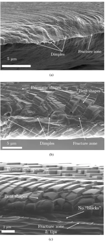
Figure 13: SEM observations of fracture regions of the thin tensile samples, (a) for the reference material and (b,c) for the irradiated material
applied strain, is gradually less operating with increasing strain. In order to assess this statement further - which is relevant for the description of voids impingement (Fig. 11) - fracture sur-faces of the tensile samples (both reference and irradiated ones)
555
have been observed with SEM.
Fracture occurs through almost complete necking in both reference and irradiated material with very limited fracture sur-faces (Fig. 13). Few dimples are present, showing rare void growth events, which is rooted into the small thickness of the
560
samples thus to a low density of inclusions. In the reference material (Fig. 13a), deformation mode is found to be homoge-neous. On the contrary, the irradiated material shows traces of localized plastic flow (Fig. 13b,c). Interestingly, different de-formation modes are observed depending on the distance from
565
the fracture surface. Far from the fracture surface and outside the necking region, undeformed prismatic blocks are observed (Fig. 13b), indicating that plasticity was localized in the chan-nels in between these blocks. Far from the fracture surface but in the necking region, these prismatic blocks have a bent shape
570
(Fig. 13c), which means that plastic deformation does not only appear in between the blocks through localized plastic flow, but also inside the blocks. This indicates that the multiplication of channels is not the only mechanism leading to more homoge-neous deformation mode, but also homogehomoge-neous deformation
575
mode appears in between channels. In the immediate vicin-ity of the fracture surface, prismatic blocks seem to disappear due to the high level of plastic strain, and deformation is ho-mogeneous down to very low scales (as can be observed on the fracture zone in Fig. 13c). These fractographic observations are
580
found to be also in line with the numerical results proposed in [58], especially regarding the ability of multiple slip activation (necessary in the necking region due the complex stress/strain states) to suppress localized plastic flow.
As deformation mode gradually moves from localized to
585
homogeneous, this raises the question of using continuous plas-ticity framework to model ductile fracture through void nucle-ation, growth and coalescence in irradiated materials. Although not assessed in this study, void nucleation is expected to be influenced by dislocation channeling that may lead to severe
590
local plastic strain and create voids, e.g., following a mecha-nism described in [84]. However, void growth and coalescence, mostly concerned with large strains and high stress triaxiality (that somehow weakens localized plastic flow), are expected to be far less influenced by dislocation channeling
deforma-595
tion mode as shown by the experimental results obtained in this study. Therefore, these results argue for a simplified modelling of ductile fracture in materials exhibiting dislocation channel-ing by uschannel-ing models derived under the assumption of homo-geneous deformation mode. Moreover, the experimental
re-600
sults presented in Section 3 can be used to assess, calibrate and improve crystal plasticity constitutive equations developed to describe the mechanical behavior of single crystals within the framework of continuum mechanics, for both reference mate-rial and for the matemate-rial exhibiting dislocation channeling. The
605
latter results could also serve as a test for Dislocation Dynamics simulations [34, 58] ability to reproduce the localization pat-terns. A complete study comparing numerical predictions to the experimental results is outside the scope of this study, but preliminary comparisons using crystal plasticity are given and
610
discussed in the next section.
4.2. Comparisons to numerical results
As discussed in Section 2.2.2, the assumed uniaxial stress loading conditions at the grain scale can be applied to the unit cell used in the simulations assuming either periodic boundary
615
(a) (b)
Figure 14: (a) Comparisons between experimental and numerical (red lines) voids shapes for different crystallographic orientations (b) Evolution of voids axis a and b (defined as the axis of an ellipse inscribed in the voids Fig. 7) as a function of engineering strain (denoted Fxx− 1= ∆l/l0, with l0the initial gage lenth of the tensile sample, and∆l the elongation) for the reference material: Comparisons between experimental (dashed lines) and numerical (solid lines) result for different void pairs (V1,V2,V4 and V5).
free surfaces). Experimental results on the reference material show that the influence of the presence of the voids on plas-ticity is rather weak, justifying the use of periodic boundary conditions that have thus been applied for the simulations of
620
voids evolutions in the reference material. The comparisons of the predicted deformed void shapes and void axis evolution as a function of the engineering plastic strain along the ten-sile axis to the experiment results are shown on Fig. 14. For voids V1, V2 and V5, simulations reproduce fairly accurately
625
both voids shapes and voids axis evolution, with no adjustable parameter, capturing the influence of crystallographic orienta-tions observed between voids V2 and V1 (or V5). For voids V4, the results do not match the experiments. Figure 15 shows the proportion of plastic slip (|γs|) in each slip system with a pie
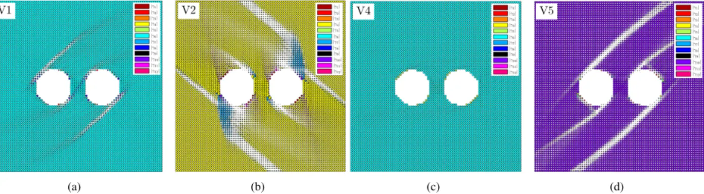
630
chart plotted for each voxel of the simulation. The surface of the pie chart is also proportional to the sum of the cumulative plastic strain P |γs|. It is shown that far from the voids, only
one system is activated, which corresponds to the experimental observations. Moreover, the activated slip system in the
simula-635
tions corresponds to the slip traces of the activated slip system in the experiments. Other slip systems are activated in some areas close to the voids, especially for voids V2, which is not observed in the experiments.
As an intermediary conclusion, the use of crystal
plastic-640
ity constitutive equations for FCC crystals appears to lead to rather satisfactory predictions in comparisons to experimental results on the reference material, with some noticeable discrep-ancies that may be related to numerical assumptions, especially
(1) uniaxial stress conditions that may be not relevant in some
645
grains due to the interactions with other grains and/or (2) the definition of engineering plastic strain which is the macroscopic one for the experimental results but local one (at the grain scale) for the numerical results.
For the irradiated material, experimental results clearly
in-650
dicate a localization pattern at the grain scale, so that periodic boundary conditions - that prevents such localization - can not be used. Therefore, simulations have been performed using free surfaces at the boundaries of the unit cell, mimicking the weak constraint imposed by the surrounding grains on the
deforma-655
tion behavior. Fig. 16 shows the typical results using the crystal plasticity softening behavior described in Section 2.2.2, using the crystallographic orientation of the grain shown in Fig. 10 up-left image. Cumulated plastic slip defined asP |γs| is plotted
to visualize plastic localization and to compare to experimental
660
results. Using a pure softening law (∆τ2 = 0 in Eq. 16), a
lo-calization pattern is observed (Fig. 16(a)) where two principal bands appear close to the void boundary. These bands corre-spond to the activation of only one slip system which is the one having the highest Schmid factor. Interestingly, as observed
665
experimentally, a second band is observed linking the void and the main slip band in the same way observed in the experiments. However, the slip system contributing to this second band does not correspond to the slip system activated in the experiments. Using the softening-hardening law (Eq. 3 with∆τ2 , 0), the
670
localization pattern observed in Fig. 16 first appears, and then bands spread out, leading to a transition from dislocation
chan-(a) (b) (c) (d)
Figure 15: Proportion of the activated slip systems (|γs|) close to the voids and at the surface of the sample, represented by a pie chart in each voxel of the simulation. Surface of the pie chart is proportional toP
s
|γs|, (a) V1 (b) V2 (c) V4 (d) V5. Far from the voids (not shown here) only one slip system is activated
neling deformation mode to homogeneous deformation mode observed in the experiments, although nucleation of secondary bands can not be reproduced with such simple modeling.
675
(a) (b)
Figure 16: Cumulated plastic slip defined asP |γs| resulting from the simulation of a FCC single crystal under uniaxial stress loading conditions (accounting for free surfaces), using the hardening law described in Eq. 3, with (a)∆τ2 = 0 and (b)∆τ , 0, for the crystallographic orientation corresponding to Fig. 10a up left image
5. Conclusions and Perspectives
Homogenized models developed for porous materials in the context of ductile fracture modeling assume implicitly homoge-neous deformation mode at void scale in the sense that no strain localization appears at a lower scale. However, some materials
680
such as metals quenched, heavily cold-worked or irradiated do present heterogeneous deformation mode at the grain scale re-lated to the presence of defects. The so-called dislocation chan-neling deformation mode is almost always observed in irradi-ated materials that fail in most cases through a void growth to
685
coalescence fracture mechanism. The influence of dislocation channeling deformation mode on void growth to coalescence has been studied experimentally based on model experiments at the grain scale, through comparisons to a reference material deforming homogeneously. In both cases, an influence of
crys-690
tallographic orientation on voids evolutions under mechanical loading is observed, consistent with previous studies. A strong effect of dislocation channeling on voids evolutions is observed
at low applied strain through the appearance of characteristic channels patterns interacting with voids. However, gradual
ac-695
tivation of secondary dislocation channels tends to lead to more and more homogeneous deformation mode with increasing ap-plied strain. These observations have been made on low stress triaxiality tests, but the effect of dislocation channeling mode is expected to be even weaker for higher stress triaxiality for
700
which multiple slip is activated. The experimental results argue for a simplified modelling of ductile fracture in materials show-ing a propensity to localization at the grain scale due to dislo-cation channeling deformation mode, at least when fracture is driven by void growth to coalescence, by using homogenized
705
models for porous materials developed for materials deforming homogeneously. For materials where fracture is driven mainly through void nucleation, an influence of dislocation channeling may be expected, due to potential local high stresses/ strains, that remains to be studied.
710
Comparisons of experimental to numerical results regard-ing voids deformations in FCC sregard-ingle crystals performed in this study indicate that the use of crystal plasticity constitutive equa-tions is able to reproduce quantitatively some experimental ob-servations such as voids evolutions in the reference material
715
and (partly) the localization pattern for the dislocation chan-neling material. However, for the reference material, a good agreement is observed by using boundary conditions inferred from experimental observations, i.e., periodic boundary con-ditions that prevents strong localization. Interestingly, more
720
realistic simulations for the reference material that consider a 2D polycrystalline aggregate with free surfaces with voids at the grain scale lead to strong localization through the appear-ance of a slip band crossing the voids, which is not observed in the experiments. Such localization is in fact rooted in the
725
crystal plasticity constitutive equations used where the param-eters κ and Gchave been calibrated through comparisons to a
tensile curve on a polycrystalline aggregate. The values of the parameters lead to a softening behavior in the case of single slip, thus localization in the case of uniaxial stress state. This
730
emphasizes the fact that calibration of crystal plasticity consti-tutive equations should be performed at the single crystal scale to lead to quantitative - and even qualitative - behavior con-sistent with experimental results. For the material exhibiting
dislocation channeling, the use of an ad-hoc softening
behav-735
ior mimicking more complicated formulations proposed in pre-vious studies reproduces somehow the localization pattern and phenomenologically the transition between localization and ho-mogeneous deformation mode. However, such simple model-ing can not trigger the gradual activation of additional channels
740
which deserves attention in further studies with respect to phys-ical mechanism involved and numerphys-ical modeling.
Finally, interactions between dislocation channels and voids have been studied for voids sizes (∼ 1µm) larger than chan-nels widths (∼20nm). As irradiation can also lead to nanovoids
745
(as shown in Appendix A) of typical sizes lower than chan-nels widths, another kind of interaction can also be observed, as shown in Fig. 17, where nanovoids deform inside a disloca-tion channel. A full descripdisloca-tion of such phenomenon, as well as the potential implication regarding ductile fracture of irradiated
750
materials, remain to be studied.
(a) (b)
Figure 17: TEM observations of interactions between nanovoids and a dis-location channel under (a) underfocus condition where voids are white spots surrounded by a black line and (b) overfocus conditions where voids are black spots surrounded by a white line. Voids are not observed inside the channel as a consequence of void rotation and closure under large shear strain
6. Acknowledgements
The authors would like to thank V´eronique Cloute Cazalaa and Elodie Rouesne for their help with Scanning Electron Mi-croscope observations, and Lionel G´el´ebart for the use of the
755
AMITEX FFTP solver. This project has received funding from the Euratom research and training programme 2014-2018 un-der Grant Agreement N◦661913. This work reflects only the authors’ view and the Commission is not responsible for any use that may be made of the information it contains.
760
7. Appendices
7.1. Appendix A: Irradiated material
The microstructure of the irradiated material has been char-acterized through Transmission Electron Microscopy (TEM) observations performed on a FEI Tecnai G2 300kV. Disk-shape
765
thin foils (diameter 3mm, thickness 100µm) sampled at the sur-face of an irradiated specimen have been obtained by mechan-ical polishing. Electrolytic polishing finally allows to get ar-eas of thickness about 100nm that can be observed by TEM.
Typical bright and dark fields TEM observations are shown on
770
Fig. 18(a,b), showing two types of irradiation defects, namely nanovoids and faulted dislocations loops/ Frank loops that lie in (111) planes. Frank loops are observed in dark field con-dition by selecting g=1/2(311), while voids are differentiated from over microstructural features using underfocus/ overfocus
775
observations. Size distributions of voids and Frank loops are shown on Fig. 18(c,d), with average sizes of 3.7nm and 6.1nm, respectively. Assuming a mean thickness of the TEM foils of 150nm, voids and Frank loops densities have been evaluated to 2.0 1021m−3and 5.3 1022m−3, respectively. 780 (a) (b) 0 5 10 15 20 25 30 35 40 Diameter (nm) 0.000 0.025 0.050 0.075 0.100 0.125 0.150 0.175 Frank Loops (c) 0 1 2 3 4 5 6 7 Diameter (nm) 0.00 0.05 0.10 0.15 0.20 0.25 0.30 0.35 Voids (d)
Figure 18: (a) Dark Field TEM image (obtained by selecting g=1/2(311)) al-lowing to observe Frank loops (b) Bright Field TEM images showing the pres-ence of nanovoids. (c,d) Size distribution of Frank loops and nanovoids
The Vickers hardness of irradiated samples has been mea-sured to be 310 ± 14 HV0.02 using the same conditions as for
the reference state (20g with 10s hold time). The increase of hardness is thus equal to ∆HV = 117, in agreement with the
Frank loop density and size measured (as the major contributor
785
to hardening) following the correlation explained for example in [85].
7.2. Appendix B: Numerical simulations
Numerical simulations using crystal plasticity constitutive equations (detailed in Section 2.2.2) and compared to experi-mental results have been performed using AMITEX FFTP Fast Fourier Transform based solver [72]. This numerical method, first introduced by [86], relies on structured grids (composed of voxels) subjected to periodic boundary conditions where the displacement field u is:
where F is the macroscopic (volume average) deformation gra-dient tensor, and u? a periodic fluctuation. Macroscopic
de-790
formation gradient F can be prescribed, or either macroscopic Cauchy stress σ (through finding the corresponding macroscopic deformation gradient by an iterative procedure). A finite strain extension of the original FFT method is implemented in AMITEX FFTP by solving the equilibrium equation using first Piola-Kirchhoff
795
stress tensor on the reference (undeformed) configuration [72]. Each voxel of the structured grid can be assigned different con-stitutive equations. The code generator MFront [87] has been used to implement the finite strain crystal plasticity constitutive equations. Details about the implementation can be found in
800
[74, 81].
Although FFT method relies on unit cell subjected to peri-odic boundary conditions, free surfaces can easily be added by considering stress-free voxels at the boundaries of the unit cell,
805
as shown on Fig. 19a.
(a) (b)
Figure 19: (a) FFT discretization of a plate with two cylindrical voids subjected to uniaxial stress loading conditions by adding free surfaces. (b) Corresponding Finite Element mesh
As a validation test, a FFT simulation of a plate with two cylin-drical holes is performed under uniaxial loading conditions (Fig. 19), assuming von Mises plasticity with isotropic hardening (R(p)= R0+ Q1[1 − exp(−b1p)]. {R0 = 126 MPa, Q1 = 219 MPa
810
b1 = 7}), and the evolutions of void axis {a, b} are compared
to reference results obtained in [82] with the Finite Element Method (FEM). Details about the reference simulation can be found in [82], and a typical mesh used in shown on Fig. 19b. Stress-free voxels are used for the voids and also to model free
815
surfaces (on all side of the cell except along the tensile direc-tion), as shown on Fig. 19a. Average deformation gradient is applied along the tensile direction. As for finite element simu-lations, cumulative plastic strain is measured far from the voids. Size of the normalized axis a and b as a function of the far field
820
plastic strain are compared in Fig. 20. Results show a good agreement between both FFT and FEM simulations, validating the use of FFT solver considering free surfaces.
0
1
2
3
4
5
6
7
Cumulative plastic strain %
0.95
1.00
1.05
1.10
1.15
1.20
1.25
1.30
1.35
a a
&
0b b
0 FEM FFTFigure 20: Evolution of voids axis a and b (defined as the axis of an ellipse inscribed in the voids) as a function of far field plastic strain. Comparisons between reference results from [82] obtained by the Finite Element method (FEM) to FFT simulations
For all simulations performed in this study, structured grids shown in Figs. 6 and 19a are used. Stress-free constitutive
equa-825
tions are assigned to the voxels corresponding to the cylindri-cal voids (and to the free surfaces for Fig. 19a), while crystal plasticity constitutive equations (described in Section 2.2.2) are assigned to the remaining voxels. Orientation of the crystal is given by the experimental EBSD analysis. Deformation
gra-830
dient Fxx along the tensile axis is prescribed, and all Cauchy
stress tensor components - except σxx- are set to zero to model
uniaxial stress state. Convergence with respect to the number of voxels used has been carried out, and 301 voxels are typically used along the in-plane length. As FFT method computes only
835
deformation gradient and stress tensors for each voxel, a post-processing is applied to recover displacement field by solving the compatibility equation [72], leading to the evolution of void size as a function of the prescribed deformation gradient.
7.3. Appendix C: Observation of dislocation channels
840
A Transmission Electron Microscope (TEM) sample was extracted (using FIB lift-up technique) perpendicular to the steps observed on sample surface, as shown in Fig. 21(a). TEM ob-servation shows that these steps correspond to narrow bands where Frank loops irradiation defects have been largely removed,
845
thus appearing clear on TEM bright field images (Fig. 21(b)). The typical channel width is about 20nm or less. As the steps of the channels on the sample surface can be estimated to be about 1µm high, shear strain can be evaluated to be about 5000%.
![Figure 1: (a) Slip traces observed at the surface of a sample of irradiated austenitic stainless steel subjected to uniaxial stress loading conditions (taken from [52]), resulting from dislocation channeling deformation mode](https://thumb-eu.123doks.com/thumbv2/123doknet/12949772.375795/3.892.78.418.717.891/irradiated-austenitic-stainless-subjected-conditions-dislocation-channeling-deformation.webp)

![Figure 7: (a) Evolution of voids shapes as a function of macroscopic plastic strain inside a grain with crystallographic orientation [106 ◦ , 156 ◦ , 207 ◦ ] (Euler angles orientation with the Bunge convention (zx'z'') obtained through EBSD on the other si](https://thumb-eu.123doks.com/thumbv2/123doknet/12949772.375795/7.892.67.828.121.357/evolution-function-macroscopic-crystallographic-orientation-orientation-convention-obtained.webp)