The Design and Analysis of a Large Angular Range, Two-Axis Flexure Assembly
by
Barry A. Gin
SUBMITTED TO THE DEPART MENT OF
MECHANICAL ENGINEERING
IN PARTIAL FULFILLMENT OF THE REQUIREMENTS
FOR THE DEGREES OF
MASTER OF SCIENCE IN MECHANICAL ENGINEERING and
BACHELOR OF SCIENCE IN MECHANICAL ENGINEERING
at the
MASSACHUSETTS INSTITUTE OF TECHNOLOGY
February, 1988
C Barry A. Gin
The author hereby grants to MIT and Hughes Aircraft Company permission to
reproduce and to distribute copies of this thesis document in whole or in part.
Signature of Author
Certified by
Accepted by
DeparTmift of M4/hanical Engineering February, 1988
. - ,' X ---
Professor Igor Paul Thesis Supervisor
Professor Ain Ants Sonin
Chairman, Department Graduate Committee
MASSACHUSEiI iSTiu'rTE OF TECHNOLOGY
MAR 18 1988
Exhibit C
ENGINEERING INTERNSHIP PROGRAM SCHOOL OF ENGINEERING
MASSACHUSETTS INSTITUTE OF TECHNOLOGY
Cambridge, Mass. 02139..
THESIS REVIEW LETTER
Attention: John R. Martuccelli, Director, Room 1-211
Master's Thesis of Barry A. Gin
(student name)
The Design and Analysis of a Large Angular Range, Two-Axis The attached thesis, Flexure Assembly.
(Title)
has been reviewed by the undersigned Hughe's Aircraft Company
(company name)
representatives and confirmed that it does not contain details objectionable
from the standpoint of Hughes Aircraft Company
(company name)
In addition, we understand that the aforementioned thesis report becomes the
permanent property of M.I.T., will be placed in the M.I.T. Library within one
month of the date of submission and may not be published wholly or in part
except by authorization of the Department of Mechanical Engineering
(department name)
in which the student is enrolled. (It is understood that authorization is granted o the Company for such limited publication as the Company's prior
contractual obligations may require.)
Hughes Aircraft Company
Gomfapny,Narqe /o - T
of Approvd By (for/company)
Title:, , , ..
-Date: / /? 6/ Ay Da
rect Company Supervisor StudentJlaHe
: Student Date:25 Jt- 1 9 ES Subject: I i - - . -- . . te:
The Design and Analysis of a Large Angular Range, Two-Axis Flexure Assembly
by
Barry A. Gin
Submitted to the Department of Mechanical Engineering in partial fulfillment of the requirements for the degrees of Bachelor of
Science and Master of Science in Mechanical Engineering
ABSTRACT
A new concept for a large angular range, two-axis flexure assembly
using a crossed-leaf approach was designed. It was to be a brazed
assembly that would be able to have a high stiffness about its axial axis as well as in translation along all three axes, yet be rotationally soft about its radial axes. The flexure was to have an angular range of 87 mrad and was designed to meet the requirements of an application at Hughes Aircraft Company in El Segundo, California.
After a materials study, three prototypes were fabricated out of PH 13-8 Mo Stainless Steel, assembled using a two-step braze process and heat treated to obtain optimum strength and ductility.
The prototypes were tested for stiffnesses about the radial axes,
hysteresis, and fatigue life and the results compared to the
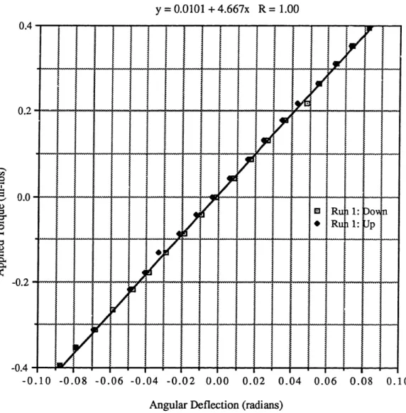
performance predictions. The stiffnesses ranged from 3.69 in-lbs/rad
to 4.67 in-lbs/rad, compared to 4.21 in-lbs/rad theoretical stiffness.
The maximum hysteresis obtained was approximately 2 mrad. The one
flexure that was fatigue tested had one blade fail after 400,000 cycles, suggesting that there were either eccentricities in the test setup or deterioration of mechanical properties due to the heating and cooling cycles of the brazing and heat treating processes.
Thesis Supervisor: Prof. Igor Paul
Acknowledgements
There were many people who enabled me to complete this project. I
would like to take this opportunity to give special thanks to the following:
- Robert Fairbanks of Scarrott Metallurgical Company, whose extreme
generosity with his time and the facilities at Scarrott enabled me to get the flexures brazed and heat treated.
- John Harrell, my company thesis supervisor, whose guidance, ideas
and advice was invaluable. Working with him was a great learning
experience for me.
- Tom Pavliscak and Dave Hiley, the managers of the Mechanical
Engineering Laboratory, for their encouragement and support. I
would also like to thank Dave Hiley for the work he did in
developing the equations in Chapter 3.
- Dave Goulding, Don Mannas, and Dave Bronson, engineers and
scientists at Hughes, for their technical support and suggestions. - Jeff Barina, a co-worker who was a great help in selecting the
materials, coming up with ideas, and solving problems.
- Allison Sheridan, my officemate, who was always more than willing
to offer her assistance with the project and the computer problems
and questions I had.
- The guys down in the machine shop and the Precision Mechanisms
laboratory, who machined all of the parts and were really helpful in getting the tests set up.
- My roommates, Nelson and Steve, who provided me a home away
from home.
- Rich, Howard, Wallace, and Ron, who kept me spiritually minded
during my time out here.
- Ivan, Dickson, Bob, Melissa, and Paul C., great friends who really
reached out to me during the rough times.
- My parents, whose constant love, prayers and encouragement have
always kept me going.
Table of Cntents Abstract. ... 2 Acknowledgem ents ...3 Table of Contents ...4 List of Figures ...6 List of Tables ...8 Chapter 1: Introduction ... ...9 1.1 Background ... 9
Chapter 2: A Description of the Design ... 5
2.1 Basic Concept ... 15
2.2 Basic Fabrication and Assem bly ... 7
Chapter 3: Cross-Leaf Flexure Theory ... 22
3.1 Single Pair of Blades About One Axis ... 22
3.2 Two Pairs of Blades About One Axis ... 26
3.3 Two Pairs of Springs About Two Axes ...28
Chapter 4: Design Developm ent ...3 1 4.1 Requirements Study ...3 1 4.2 M aterial Selection ... ...3 2 4.3 Blade Design Development ...3 4 4.4 Fabrication Considerations ... 7
4.4.1 The Brazing Process ... 47
4.4.2 The Heat Treating Process ... 49
4.5 Design Summary ... 4...5 4 Chapter 5: The Fabrication of the Prototypes ... 55
5.2 Brazing the Assembly...5 7 5.3 Heat Treating the Assembly...6 9 5.4 Machining Off the Protruding Ends of the Tubes ...7 1
Chapter 6: Performance Testing ... .74
6.1 Test Objectives ...7 4 6.2 Test Setup and Procedure ... 7 4 6.2.1 Static Stiffness and Hysteresis Measurements ... 7 6 6.2.1.1 Experimental Error ... 7 9
6.2.2 Fatigue Testing ... 8 0...
Chapter 7: Test Resuils and Analysis ... ... .8 2 7.1 General Characteristics...8 2 7.2 Static Measurements ... 8 2 7.2.1 Stiffness ...8 2
7.2.2 Hysteresis ...89
7.3 Fatigue Test Results ...9 1
Chapter 8: Conclusions and Recommendations ...94
Bibliography ... 97
Appendix A: Data and Graphs...9 8 Appendix B: Detail Drawings ... 164
List of Figures
Figure No. Title Page
1.1 - Bendix Flex Pivot ... ...10 1.2 - Elliptical Post Flexure ... 1 2 2.1 - Exploded Isometric View of the Concept ... 1 6
2.2 - Jigging Tube... ...18
2.3 - Brazing of the Blades into the Jig ... 1 8 2.4 - Brazing of the Jig Assemblies into the Frame Pieces ... 1 9
2.5 - Completed Assembly After Machining Off Protruding
Ends of Tubes ...2 1 3.1 - A Single Pair of Blades ... 23
3.2 - Vertical Translational Stiffness Assuming
Small Deflections ... 23 4.1 - Lateral Natural Frequency vs. Length of Blades ... 3 9
4.2 - Bottom View of Assembly Showing Bridge Length and
Clearance Between Blade and Outer Diameter ...4 1 4.3 - Blade Width vs. Blade Thickness for a = 0.363" . ...43 4.4 - Initial Blade Design ... 44
4.5 - Effect of Variation in Solution Treatment Temperature.52
5.1 - Application of Powdered Filler Material for
Jigs #1, 3, 4, and 5 ...5 9
5.2 - Radiographic Photo of Blade and Jig Assembly #3 ...6 1
5.3 - Filler Material Placement for Wetting and
Pull-Through Experiment...64 5.4 - Placement of Nicoro Foil for Jig Assembly #2 ... 67
6.1 - Setup for Static Stiffness Measurements ... 77
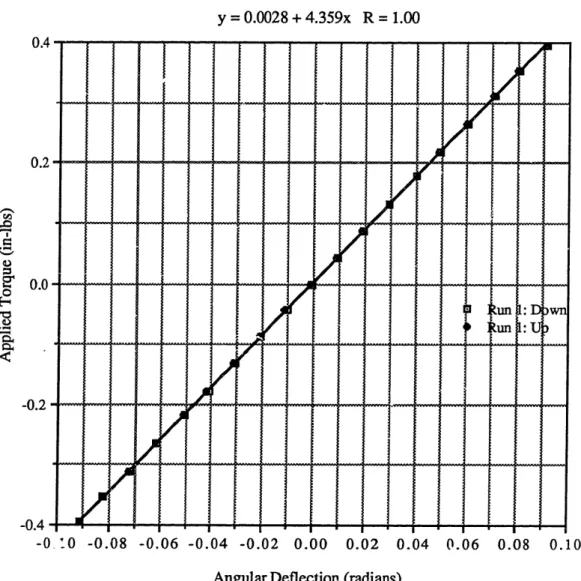
6.2 - Fatigue Test Setup ...8 1 7.1 - Torque vs. Angular Deflection for the X Axis
of Flexure 2 ... 8 5
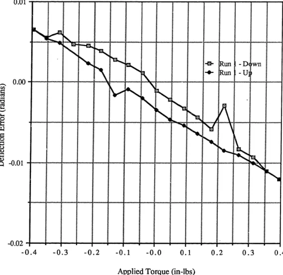
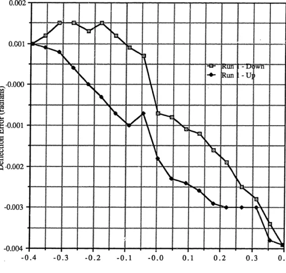
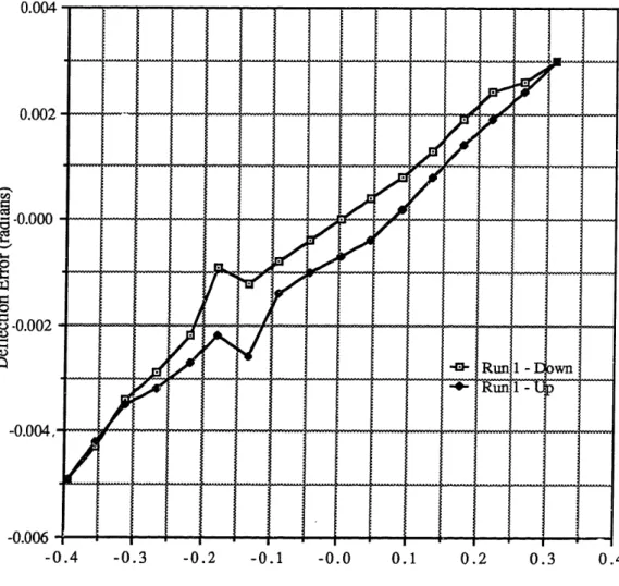
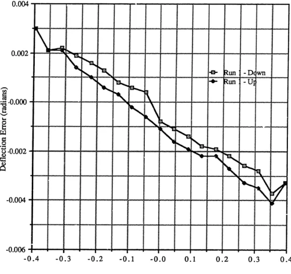
7.2 - Deflection Error vs. Torque for the X Axis of Flexure 2...8 6 7.3 - Normalized Error Curve for the X Axis of Flexure 2...8 8
List of Tables
Table No. Title Page
3.1 - Performance Equations for a Two-Axis Flexure
Assem bly ...3 0
4.1 - Application Parameters and Requirements ...3 2
4.2 - Comparison of 420 CRES and PH 13-8 Mo ...35
4.3 - Lateral Natural Frequencies for Various Blade
Lengths, Thicknesses, and Nominal Distances ... 3 7
4.4 - Performance Predictions for a 0.009" Thick Blade ...46
4.5 - Mechanical Properties for Various Age Hardened
C onditions ... 0
6.1 - Comparison of Application Driven Mass and
Test Inertial Mass ... 75
7.1 - Data from the x axis of Flexure Assembly ... 8 3 7.2 - Summary of the Results of the Static Stiffness
Measurements ... 8 7
CHAPTER 1
Introduction
1.1 Background
In many aerospace precision mechanisms, a variety of
applications call for the use of flex pivots. These pivots basically are mechanisms which allow a driven mass to flex about one or more axes
of rotation. Many kinds of springs would be able to serve this purpose
about one axis of rotation. One such spring is the cross-leaf flexure,
which consists of two leaves, or blades, arranged in an 'X' configuration.
One side of the 'X' is connected to ground while the other side is attached to the flexing element, which theoretically pivots about the
axis created by the intersection of the two blades. A significant
advantage to using the cross-leaf spring is that there is no sliding or
rubbing contact between the members. Because of this, there is
absolutely no wear of parts due to friction, and no lubrication is
necessary. Another advantage is the insensitivity of these flexures to
contamination. In other types of assemblies where ball bearings are
used, cleanliness and careful alignment are required in order for the flexure to operate properly. With the cross-leaf flexures, tolerances do not have to be as tight, and cleanliness of the parts and their operating environment are not as critical.
A single-axis flexural pivot bearing using the same principles as the cross-leaf spring has been developed and marketed by the Bendix
Corporation. These pivots basically consist of concentric, cylindrical
members interconnected by a cross-leaf spring (Fig. 1.1). It is a brazed
-~ ~~~~~~~~~- -: -&
4
;-- 1.6 D ---.76 D-1 r---.76C- r.76C-I4 _ I .III I~~~~
Figure 1.1 - Bendix Flex Pivot
(Reprinted from "Considerations in the Applications of Flexural Pivots," Automatic Control, November, 1962,
p. 41
come in varying thicknesses, and thus, various spring rates can be
attained. Depending on the blade thickness, these pivots can have an angular range as high as 30° and an elastic deflection range of ±10° .
Because these springs are only capable of flexing about one axis of
rotation, four of them must be used to construct a two-axis flexure,
which is much more complicated than a single-axis flexure. A two-axis flexure, as the name implies, enables a driven mass to pivot about two axes. Many of the applications in the aerospace industry call for other
requirements which are rather difficult to meet. These requirments
include a sufficient angular range, a high axial stiffness while having a
relatively low radial stiffness, high translational stiffnesses along all three axes, as well as certain natural frequency requirements, infinite fatigue life, and a high g-load carrying capacity. Four Bendix flexures would likely be able to meet most of these requirements of a two-axis
flexure. This four flexural pivot design, however, would be quite
expensive because it would require a number of parts that would have to be aligned and pinned with a high degree of precision. Fasteners for this type of arrangement would be rather bulky and take up space. Since aerospace precision mechanisms are required to be of minimal
size and weight, this type of configuration would not be ideal.
The axis elliptical post flexure (Fig. 1.2) is one type of two-axis flexure which has been commonly used for several applications.
Its main flexing element is a post machined out of titanium. An
elliptical curve is machined out of this post such that the smallest
cross-sectional area is in the middle. This is done to minimize any
stress concentrations at the interfaces. The flexure is able to pivot in
S-Bar Elliptical Post
'x
Figure 1.2 - Elliptical Post Flexure with S-Bar
/
circling the post and connected to the opposing elements, keeps the
flexure from pivoting about the axial axis. This ring is thin so that it does not add significant stiffness to the axes about which the flexure is
to pivot. The axial compressive strength of the post keeps the flexure
stiff in translation along the axial axis, and both the S-bar and the post contribute to the stiffness along the radial axes. The elliptical post with
S-bar has several advantages. Like the cross-leaf, single-axis flexures, it has low friction and hysteresis, a low predictable spring rate, a relatively simple design, and quantities such as stiffnesses and stresses
which are easy to analyze.
There are, however, several disadvantages to the elliptical post flexure. First of all, it is quite limited in angular rotation, having a
maximum angular travel of about 5 mrad. Some applications require
an angular travel of about 90 mrad, almost 15 times the maximum
travel of the elliptical post. Another major disadvantage is the
manufacturing complexity and high cost. Because of its shape, the
elliptical cross-section is rather difficult to machine. The assembly
must be heat treated to give it maximum strength, and then hand polished to a very high finish because surface defects would shorten
the fatigue life.
Because of the shortcomings of the four flexural pivot design and
the elliptical post with S-bar flexure, as well as new applications being
proposed requiring multi-degree angular travel, a new concept for a
two-axis flexure is desired. Such a flexure would need to maintain the
compact packaging of the elliptical post flexure, have the low stiffness capability and large angular range of the four flexural pivot design, yet still maintain simplicity in design and be inexpensive to manufacture.
A concept for a large angular range, two-axis flexure assembly
meeting the above requirements has been proposed. It works basically on the same principle as the cross-leaf pivots, yet does not take up the
large amount of space that would be needed if the Bendix flexure pivots were used. This concept should also have much better stiffness and natural frequency characteristics than do the previous concepts. Another advantage is that it should not be as difficult to manufacture as the elliptical post flexure.
A prototype of this concept was designed, fabricated, and tested to
analyze its performance characteristics and ease of fabrication. Quantities such as stiffilesses, natural frequencies, and fatigue life were
to be analyzed to see whether or not this new concept was practical
CHAPTER 2
A Description of the Design
2.1 Basic Concept
An isometric drawing illustrating the basic components of the design as initially proposed is shown in Figure 2.1. It is comprised of four basic elements; the top frame, the middle frame, the bottom
frame, and the blades. The bottom frame is grounded to a stationary
platform. The driven mass is attached by four bolts to the middle
frame. This frame piece is the pivoting element of the flexure, and is
able to flex about the x and y axes. Slots are cut into these two frame
pieces, and two pairs of blades, which are the flexing elements, are brazed into these slots. The other ends of these blades are brazed into the top frame, which holds the entire assembly together.
The middle frame is able to pivot freely about the y axis using the
set of blades which attach it to the top frame as the flexing elements. When this happens, the top frame is held stationary by the blades
attaching it to the bottom frame. However, when the middle frame
pivots about x, the blades attaching it to the top frame move the top frame along with it, and the blades attaching the top frame to the
bottom frame are the flexing elements. Theoretically, the pivoting
about x is independent of the pivoting about y.
Because of the arrangement of the blades in this configuration, the flexure should be rotationally soft about the x and y axes. It should, however, be quite stiff in rotation about the z axis as well as in translation. These quantities will be analyzed in a later section.
z
.L
Figure 2.1 - Exploded Isometric View of the Concept
There are several advantages to this concept. First of all, it is simple in design. There are only four unique parts to the design, all
which are rather simple in form and can be easily machined. Another advantage is that it can be made out of a low cost material, such as 410
CRES or another high strength stainless steel. Since it is a brazed
assembly, it requires no mechanical fasteners, which tend to wear or
loosen over a period of time. Like the elliptical post flexure, it is a very
compact package, yet can have the large angular range that many of
the new applications require. Because of these advantages, this new
concept would be very superior to the existing flexures.
2.2 Basic Fabrication and Assembly
One major limitation to the initial concept illustrated in Fig. 2.1
was the difficulty in cutting the slots into which the blades were to be brazed. Since alignment of the blades with respect to the axis about
which they flex as well as the alignment of the two opposing slots for each individual blade was very important, attaining the tolerances required in these slots would have been a rather slow, difficult, and
expensive process. A solution to this problem was proposed and
implemented. Instead of cutting these slots into the main frame pieces, these slots would be cut into a jigging tube, which is illustrated in
Figure 2.2. A single pass with a slitting saw would be able to make the
two slots necessary for one blade while another pass would make the
two slots necessary for the other blade. Once this was done, the blades
would be brazed into these slots as shown in Fig. 2.3. After this
process, four of these blade and jig assemblies would be brazed into the frame pieces as illustrated in Fig. 2.4. Once the entire assembly was
Figure 2.2 - Jigging Tube
Figure 2.3 - Brazing of the Blades into the Jig
N i-4 a) 1-4 c , *-4 oz AX 04
heat treated, the protruding portion of the jigs would be machined off,
resulting in the finished assembly (Fig. 2.5). The advantage of using
such a two-step braze process was that should one of the blade and jig
assemblies fail to align properly or obtain a good braze joint, the fault
could be detected and the defective blade and jig assembly easily
discarded and replaced without ruining the entire assembly. Hence,
there would be a much better chance of getting quality flexures without any defects because good blade alignment and braze joints are assured.
to
b
0 C-.- e C U ~ O C a) -© 50CHAPTER 3
Cross-Leaf Flexure Theory
Most of the analysis for the two-axis cross-leaf flexure can be
done using beam theory for small deflections. To obtain performance
predictions for the two-axis flexure, the equations from beam theory can be applied to a single pair of leaves, or blades, then these results
applied to a pair of springs about one axis, and finally, the results from
a pair of springs used to obtain predictions on performance for two
pairs of springs about two axes.
3.1 Single Pair of Blades About One Axis
For a single pair of blades, as shown in Figure 3.1, the rotational stiffness about the x axis is determined by the following equation:
2EI
kx 2EI (3.1)
where E is the elastic modulus of the material, I is the moment of inertia (bt3/12), and is the length of the leaf. By substituting in for
the moment of inertia, the following expression is obtained:
Ebt3
kx= 61 (3.2)
I
t
Figure 3.1 - A Single Pair of Blades
F F '2F F I VT AE
x ·
=,
Iv
aV
6=
Fl
AE F AE v 8v I k = EbtFigure 3.2 - Vertical Translational Stiffness Assuming Small Deflections
l --
1l
F 2 -B~,,,, , , , , , ,, -I I I Qx -- p
By assuming small deflections, the translational stiffness along the
z axis is found to be (Fig. 3.2):
Ebt
k l/N
z I (3.3)
When determining the stiffness of the pair of blades along the x axis, both the s'lear stiffness of the blades as well as their bending
stiffness must be taken into account. By combining equations for shear stress and strain, the shear displacement along the x axis due to a load F applied on the top of the blades in the x direction is:
Fl s - Gbt
s Gbt
(3.4)
where G is the shear modulus of the blade material.
displacement due to the same applied force is:
The bending
Fl3
§b- Etb3 (3.5)
By combining these displacements, the total stiffness along the x axis for two blades becomes:
2Gbt
The critical buckling load due to a force in the z direction can be
determined using the model for a simple cantilever beam with both
ends fixed. This quantity is determined by the following:
F = cr 4 2 EI 2 (3.7)
A force F in the z direction gives a resultant compressive force of F/I'2 along the axis of the blade. A force in the y direction will result in this same force acting on one of the blades. Therefore, by substituting this
into Eq. 3.7 and substituting in the variables for the moment of inertia,
the critical buckling load along the z axis becomes:
-\2,t2Ebt3
F cr = 312 (3.8)
yz
The critical load along the x axis can be determined using the lateral buckling load for a beam in bending under the condition that
both ends are fixed. This equation can be found in Strength of
Materials by F. R. Shanley. For one beam, the critical lateral buckling
load is:
F = 0.6413 (3.9)
X cr 12
If we assume that the loads are equally shared by both blades in the spring, then the critical load can be doubled. Therefore, the critical
load for a pair of blades becomes:
F = 1.2826 Eb (3.10)
xcr 12
Another important quantity in the analysis of the flexure is the bending stresses due to flexing. If the top component of the flexure blades flexes an angle , then the resulting maximum bending stress at
the middle of the blade is:
Et
2l (3.11)
3.2 Two Pairs of Blades About One Axis
Since the equations for a single pair of blades about one axis have
already been derived, the equations for two pairs of blades about the
same axis is a rather simple process. One can obtain the stiffnesses of
this system by treating the two pairs of blades as two springs in
parallel. Since the stiffnesses of two springs in parallel add, the
resultant stiffnesses of this two pair configuration are double the stiffnesses of a single pair of blades. Assuming symmetry of loading, the buckling loads are also doubled because there are twice as many members resisting the forces applied. The only quantity that does not change is the bending stress due to rotation about the x axis, which is
only dependent upon and independent of the number of blades used.
Hence, for a single axis pair of springs, the performance characteristics are governed by the following equations:
Ebt3
kx - 31
Translational stiffness along the x axis:
k 4Gbt
X I
Translational stiffness along the y and z axis:
2Ebt
k =
y,z I
Critical load along the x direction:
Ebt3
F = 2.56 -2
X cr 12
Critical loads along the y and z directions:
Fcr yz
- 2272Ebt32
312
Bending stress due to rotation about the x axis:
OEt A 2 1 (3.12) (3.13) (3.14) (3.15) (3.16) (3.17)
3.3 Two Pairs of Springs About Two Axes
For the two-axis flexure using two pairs of springs (or four pairs of blades) in the configuration shown in Fig. 2.1, the system can be modeled as two springs in series when determining the translational stiffness along the x or y axis. The reasoning behind this is that a force
acting on the middle frame is transmitted first to the top frame by the
blades connecting these two pieces. This in turn is transmitted to the bottom frame by the blades connecting the top to the bottom frame. Therefore, the translational stiffness of two pairs of blades along the x axis (Eqn. 3.13) is put in series with the translational stiffness of two
pairs of blades along the y axis (Eqn. 3.14). The resulting translational stiffness of the flexure along the x and y axis becomes:
4Ebt
k
=k
(3.18)
2+--+
/
G
For the rotational stiffness about the z axis, the system can also be
modeled as two springs in series. This quantity is found by using the
translational stiffness in the y direction from Eqn. 3.14, which will now be called the lateral stiffness k. By definition, the stiffness about the z direction is:
M
Mk Fa
=(3.19)
Fadeflection about z. For small deflections:
8
0 -a (3.20)
and by substituting this into Eqn. 3.19, the following is obtained:
F 2
kz =a2
(3.21)
In linear translation, F/8 is the lateral stiffness k. Therefore, by
substituting this into Eqn. 3.21 and taking two of these springs in
series, the rotational stiffness about the z axis is:
Ebta2
kez I (3.22)
Similarly, the translational stiffness of the entire assembly along the z
axis can also be determined by modeling the system as two springs in
series, using the translational stiffness in the z direction. Thus, for the entire assembly, the translational stiffness along this axis is:
Ebt
k =EN (3.23)
Table 3.1 is a summary of all the equations described above for a
two-axis flexure. From these equations, all of the quantities necessary in predicting the performance of this two-axis flexure can be obtained.
- Performance Equations for a Two-Axis Flexure
Rotational Stiffness
Ebt
3About x and y k0x ky - 31
Rotational Stiffness Ebta2
About z kez I
4Ebt
Translational Stiffness k =y
Along x and y
Translational Stiffness
Ebt
Along z z
2/' 2i2 Ebt3
Critical Axial Load F =
cr 312
Ebt3
Critical Lateral Load F = 2.56
r 12
Bending Stress Due to OEt
Rotation about x and y 21
CHAPTER 4
Design Development
4.1 Requirements Study
There were several projects at Hughes Aircraft Company which
called for the use of these two-axis flexures. The angular range
requirements of these applications ranged from 13 to +87 mrad, while
the weight of the driven masses varied from 1.8 lbs. to 36 lbs. There
were various other criteria that were given, including natural
frequencies, critical loads, and size requirements. A comparison study
was done to determine which application the prototype was to be
designed. After sotie preliminary analysis, it was recommended that
the prototype be designed to meet the requirements of the application
that required the highest angular range. This application was chosen
for several reasons. First of all, a high angular range was one of the
most important features of this two-axis concept. Therefore, since the
angular travel requirements of this application were roughly six times that of the others, designing the flexure to meet this requirments would give a much better picture of the capabilities of this design. Secondly, there were other shortcomings to the other applications which would have made the flexure more difficult to test or to
assemble. One application had a driven mass weighing almost 40 lbs.,
which would have made the assembly and testing more difficult. Another application would have also been more difficult to assemble because it was determined that the blade lengths that would be
Table 4.1 shows a summary of the parameters and requirements
of the chosen application.
Table 4.1 - Application Parameters and Requirements
4.2 Mater;al Selection
The critical element of these flexures was the flexing elements, or the blades. It was important that these blades be made of a material that would be able to flex the required angles and have an infinite life
when implemented. It also would have to be strong enough to support
the weight of the driven mass as well as the middle and top frames.
Originally, these blades were intended to be made out of Type 420 Corrosion Resistant Stainless Steel (CRES). The main reasoning behind this was that this was the material that Bendix used in their flex pivots.
Flexure Diameter 1.00 in
Weight of Driven Mass 1.81 lbs
XX Iv 0.038 in-lbs-sec 2
Iz z 0.074 in-lbs-sec 2
Angular Travel + 87 mrad (± 5° )
Natural Rocking Frequency < I Hz
About x and y
Natural Frequency about z 40 Hz
Lateral Natural Frequency 550 Hz
Type 420 is a high strength martensitic stainless steel with a tensile strength of up, to 230 ksi and a yield strength of 195 ksi when
hardened at a temperature between 1800-1900 F and tempered at
6000 F.
Although Type 420 CRES seemed to be an ideal material, there
appeared to be several potential problems. First of all, it did not
appear that the material would respond favorably to a two-step braze
process. If the blades were hardened before brazing, the brazing
temperature would then have to be below the hardening temperature.
It appeared that even the temperatures that the low-temperature
braze alloys required could harm the heat treat properties. If the
blades were brazed before hardening, they would have to be brazed at
a temperature above the hardening temperature. At such high
temperatures, there would probably be irreversible grain growth in the
material. This would result in a deterioration of the mechanical
properties, and ultimately, a premature failure of the blades.
Another potential problem with the 420 CRES that made the material incompatible with this design was the fact that water or oil
quenching was required after the hardening treatment. This was
potentially dangerous because the blades were so thin. Water or oil
quenching could bring about a thermal shock on the blade which could cause a distortion of the blades as well as potential internal stresses within the blade, which were undesirable for this application.
The possibility of these potential problems warranted an
investigation into other materials in order to find a material that was
more suitable for this application. Such a metal would not require
to cooling rates, and would be able to go through several heating and
cooling cycles without severe deterioration of mechanical properties or
irreversible grain growth. In addition, this metal would also have the
ductility and fatigue properties which would enable it to meet the requirements of the flexure.
PH 13-8 Mo, a precipitation hardened, martensitic stainless steel
manufactured by Armco, was a material which met these
requirements. When compared to 420 CRES (Table 4.2), it had the
same, if not better, mechanical properties. It could have a tensile
strength of up to 230 ksi and a yield strength of 210 ksi. It had good
ductility properties, and most, if not all, of its mechanical properties were irrespective of grain orientation. Another advantage was that its mechanical properties were not sensitive to cooling rates. Also, if the metal was brought to a temperature above the solution treatment temperature, as would be done in the flexure assembly, the grains
could easily be refined by cooling the metal down to 600 F. rhus, the
material could undergo several heating and cooling cycles without any
significant deterioration of mechanical properties. Because of these
advantages, it was decided to machine the whole assembly out of PH
13-8 Mo.
4.3 Blade Design Development
As was shown earlier in the theoretical development, the
performance of this flexure was mainly dependent upon the material of the blades as well as its dimensions. Once the material was selected, the dimensions to obtain the desired performance were determined. This was done using the equations derived in Section 3.3 (Table 3.1).
Table 4.2 - Comparison of 420 CRES and PH 13-8 Mo Ultimate Tensile Stress 2% Yield Stress e (2 in) % Density Coef. of Thermal Expansion Elastic Modulus 420 CRES 230 ksi 195 ksi 8 .280 lb/cu. in 5.7 x 10'6 29.0 x 10⁶ PH 13-8 Mo 215 ksi 205 ksi 13 .271 lb/cu. in 5.8 x 10- 6 29.4 x 10⁶ I I ~ ~ _
For PH 13-8 Mo, the fatigue limit is 90 ksi. For the initial analysis, the fatigue limit was taken to be 50 ksi in order to put in a margin of safety. Thus, by substituting this value into Eqn. 3.17 and substituting
in for , the maximum ratio of thickness to length was obtained. By
varying the four design parameters for the blades, which are the length
1, thickness t, width b, and the nominal distance of the two blades from
center a, various performance characteristics, such as stiffnesses and natural frequencies, can be obtained.
There were several limitations to these dimensions due to size
requirements. A gap of 0.020" was desired between the blades to
insure that they would not come in contact with each other during
operation. Therefore:
a + b + .010" < .500" (4.1)
A quick analysis was done to get a rough estimate of he size of the
blades that would be needed to meet the requirements of the flexure.
The most difficult requirement to meet was the lateral natural
frequency along the x and y axis. Data showing the relationship
between the length of the blade and the lateral natural frequency for various blade widths and nominal distances from center are shown in
Table 4.3. Figure 4.1 shows the resulting graphs. From this
information, it can be seen that in order to meet the lateral natural frequency requirement, the length of the blade would have to be between 0.1" and 0.3", and that the width of the blade would have to be between 0.090" and 0.140". The thickness of the blade would also
Table 4.3 - Lateral Natural Frequencies and Thicknesses for Various
Blade Lengths and Nominal Distances from Center
For a=0.400 in, b=0.090 in:
For a=0.375 in, b=0.115 in:
Length of Blade Blade Thickness Natural Frequency
in in Hz
0.100
0.004
721.5
0.125 0.005 695.10.150
0.006
666.5
0.200
0.008
607.0
0.225 0.009 577.80.250
0.010
549.7
0.500
0.020
347.8
0.736 0.029 250.1Table 4.3 (cont'd)
For a=0.350 in, b=0.140 in:
Length of Blade
Blade Thickness
Natural Frequency
in in Hz 0.100 0.004 814.5 0.125 0.005 793.1 0.150 0.006 769.1 0.200 0.008 716.7 0.250 0.009 689.6 0.250 0.010 662.7 0.500 0.020 446.1 0.667 0.026 356.1
= 0.0396
1
o.0 15"
0.1 - 0.5 0.9
Length of Blade (in.)
Figure 4.1 - Lateral Natural Frequency vs. Length of Blades b00 N 700 a, 600 500
z 400
i 300 200 ,.Another limitation to the values of a and b was the curvature of
the outer diameter of the frame pieces. It was imperative that the
entire working length of the blade (the portion of the blade that would undergo bending during operation) be within the boundary of the outer diameter of the frames to prevent accidental machining of the blade
when the protruding portions of the tubes were machined off. If
possible, it was also desirable not to have any portion of the blade be
machined when the, protruding portions of the tu'bes were removed. A small study was done to determine the maximum distance from
the center that the outer edge of the outermost blade could be. This
was mainly dependent upon the outer diameter of the tubes. This
dimension in turn was dependent upon the size of the frame pieces.
Here, the diameter of the tubes was limited by the length of the bridge
between the opposite ends of the bottom and middle frames (Fig. 4.2). If the tube radius was too large, then the tubes would intersect each other and not fit. It was found that a gap of 0.500" between two pairs of leaves on the same axis would be able to accommodate 0.375" diameter tubes comfortably.
It was also desirable to have at least 0.100" on each side of the
length of the blades brazed into the tube. Thus, for a 0.375" diameter
tube, the maximum working length of the blade would be 0.175". A
schematic of this set-up was performed using GEODRAW, a computer
drafting software ackage distributed by the Structural Dynamics
Research Corporation (SDRC). As shown in Figure 4.2, it was found that
if a 0.375" long blade were used, and a 0.005" clearance between the corner of the blade and the outer diameter of the frame implemented to prevent any machining of the blade, the maximum distance between
Figure 4.2 - Bottom View of Assembly Showing Bridge Length and Clearance Between Blade and Outer Diameter
the center of the flexure and the outermost part of the blade would be
0.476". Therefore, Eqn. 4.1 becomes:
a + b + .010" < .476" (4.2)
The 0.500" gap between pairs of blades gave the following constraint:
a - b - .010" = .250" (4.3)
By solving these two equations simultaneously, the distance from the center of the flexure to the center of the blades, a = 0.363" and the width of the blades b = 0.103" for a .375" long blade with a working
length of .175".
Several programs were written in Pascal and 'C' to analyze the
data using these equations and to determine the optimal blade
thickness. It was decided that 0.005" would be the lower bound for the thickness because it would be very difficult to machine or surface grind
any material thinner than 0.005". A graph of these results is shown in
Figure 4.3. All of the curves shown are lower bounds. The curve for the natural rocking frequency about x and y, which is an upper bound
is not shown because it is off the range of the graph. The shaded
portion of the graph is the area where b and t may fall.
The first design of the blade is shown in Figure. 4.4. The chosen thickness was 0.007". This thickness was chosen because it was the lowest thickness that would meet all of the specifications. The smallest thickness was desirable because it would minimize the stress experienced by the blade. The radii of the fillet were positioned so that
1,
SNI 0 IK .". I , "-iA"-jr. -INli
· ,. sN 'i. I He'r . I .* s.i Z 111-' .' .. , ' .V,,n U (· :' ,,'(, o. ,'' i,:?' ' 9 ' "N '* , .1 ' All I' ,---L ' , .. ; f }5I .4. A ,ta, a.,,', ?-, 3 ." 'i ,"'I :--., ,Ilk Y. tl,I i i.<1
7 7-. -I k- -I , I I I I, .is s·ml
\
-0- bmax rx ry bmin xy -- bmin rz - bmin z -- bmin axial -0- bmin shear -*- bmin buckling CN CM I inl XC r- co U% 4z -' w N c r ] ~ WI o o 0 0 0 0 0o - - _ - -OO
0 0 0 0 0 0 0 0 0 0 0 0o
0 0 0 0 0 0 0 0 0 0 0 0 0 Thickness t (in)Figure 4.3 - Width vs. Thickness for a = 0.363
0.15 0.10 0.05 0.00 o O 0 C) Co I.- ,!+ mil -- - -I I I ---I I --- ) I I II `·"; ,'N " " . ",:1 ,i: a '----: ·. ,.I. · · . 3Y `Ic'` rfi ,Z-··.... CII j I 1 3 CI - { l r j
-- C~
m - ,,1 L Z1 r' __ 7 , · _n u -J J. ---· m J C- L I 0 r"I--i 7 C l *_ I I vd: I ' i *, "', . 'A' 1. -:,-- , , ' . , I~ I 1 I I I I . I I II I - _ - -- -- _ _ _^ I I Ir (D
00
0I * , a, -A r-) O lcJ cl i-cO d) c.) t N It-they would not be exposed outside the inner radius of the tube. This
was done to prevent any stress concentrations at the interfaces and to
make the performance more closely match the predictions. If the fillet radii were positioned so that they were exposed, the radii would not
have been taken into account in the calculations. Thus, the
performance predictions would have been inaccurate. The blade was
also designed to maximize the brazing surface area.
When the slots in the jig tubes for these blades were being machined, however, a slitting saw blade to meet the initial 0.008" slot
in the jig was not available. A decision was made to increase the slot to
accomodate a 0.010" slitting saw. This meant that the thickness of the blade would have to increase to 0.009". More analysis was done to
study the effects of this change. It was found that increasing the
thickness of the blade by 0.002" increased the stiffness of the flexures, the natural frequencies, as well as the critical loads quite a bit. The
stiffnesses about the x and y axes were more than doubled. However,
the requirements and specifications for the flexure were still satisfied
with the thicker blades. The maximum stress experienced by the
blades also increased significantly. This maximum stress was 68 ksi,
which was still under the fatigue limit of PH 13-8 Mo.
A comparison of the predicted performance characteristics for a 0.009" thick blade with the flexure requirements as well as the predicted flexure stiffnesses is shown in Table 4.4.
Table 4.4 - Performance Predictions for a 0.009" Thick Blade
Predicted
Parameter Requirement PerformancePerformance
Angular Travel ±87 mrad +87 mrad
Natural Rocking Freq. 0-10 Hz 1.7 Hz
Natural Freq. about z 40 Hz 84 Hz
Lateral Natural Freq. 550 Hz 678 Hz
Axial Natural Freq. 550 Hz 918 Hz
Critical Lateral Load -
185
lbsCritical Axial Load _ 670 lbs
Stiffness About x and y 4.205 in-lb/rad
Stiffness About z - 20520 in-lb/rad
Stiffness along x and y - 84910 lb/in
4.4 Fabrication Considerations
Two main processes were involved in the fabrication of this
flexure assembly. These were the brazing process and the heat
treating process. Since both of these processes required very high
temperatures, care needed to be taken so as to not have either process
hamper the other. It was important that the brazing process and
temperatures required did not make the metal unable to be heat treated or deteriorate its mechanical properties. It was also important
that the heat treatment did not deteriorate the braze joints. There
were other factors that were important in each process, and these factors will be discussed in the following sections.
4.4.1 The Brazing Process
Brazing is a joining process used in a large variety of applications.
The pieces joined in this process are bonded by a filler metal which has
a lower melting temperature than that of the base metals. The filler
metal comes in various forms, such as foil, wire, and powder, and is
either placed in between the metals to be joined or alongside the joint. Since the joint clearances are small, as the parts are heated, the filler metal melts and flows through the entire joint by capillary action. When the assembly is brought back down to room temperature, the filler metal solidifies and bonds the parts together.
Many factors go into the brazing process that can determine the
quality of the braze joint. They include the type of brazing method
used, the atmosphere in which the brazing is performed, the base
metals to be joined, the filler metal used to braze the two pieces, the
These must be chosen carefully in order to obtain an optimum braze
joint. Since the solution treatment temperature of the PH 13-8 Mo was at 17000 F, it was important that the filler metals used have a melting
point higher than that so that during the solution treatment, the filler would not remelt. It was also important that the filler material for the
first braze require a minimal joint clearance. This was important
because a large joint clearance would allow the blades to shift off their bending axis. Thus, by bending off of its intended bending axis, the
higher stress experienced by the blade could cause failure. It was also
important that the filler metal would not react with the base metals. Such an occurance could cause the blades to become more brittle, a characteristic undesirable in a flexure blade.
Because of these considerations, a filler material consisting of 35%
gold and 65% copper was selected for the first braze, which bonded the
blades into the tubes (Fig. 2.3). This was chosen because it only
required a 0.0005" clearance between parts. This alloy has a brazing temperature of about 19000 F, which is 2000 above the solution
treatment temperature. For the second braze, which would braze the
blade and tube assemblies into the frames (Fig. 2.4), a 82% gold and
18% nickel alloy (AWS Classification BAu-4, also known as Nioro) was
chosen. Nioro requires a gap of about 0.002" and has a brazing
temperature of 18000 F. This would allow the assembly to be brazed at
18000 F and then brought down to 17000 F for solution treatment without affecting either braze joint.
Both braze cycles were to be furnace brazed. There were basically
two different furnace atmospheres in which these could have been
vacuum. One concern was the possibility of the aluminum within the
PH 13-8 Mo rising to the surfaces during the heating, forming an oxide,
and eventually impeding the brazing process by not allowing the
surfaces to wet properly. One way to avoid this is by nickel plating the
parts to be brazed. Most of the parts in the flexure assembly could
have been easily nickel plated except for the jig tubes. Since only an electrolytic nickel plating was acceptable, it would have been nearly impossible to plate the 0.010" gaps in the tubes. However, if the
brazing was done in a very tight vacuum with a pressure of 1 x 10⁻⁵
Torr, the possibility of the aluminum forming an oxide would be very
small. Therefore, it was decided not to nickel plate the parts. The
flexure would be brazed in a vacuum furnace at a pressure of 1 x 10⁻⁵
Torr. It also could have been performed in a dry hydrogen
atmosphere, however, the brazing house used to perform the brazing process only had vacuum furnaces.
4.4.2 The Heat Treating Process
Once the assembly was brazed, it was to undergo a heat treatment
in order to attain the highest strength possible. PH 13-8 Mo requires two treatments in order to get its high strength properties. The first
treatment is a solution treatment, which brings the material to
Condition A. The material is usually sent from the mill in Condition A,
solution treated at 170C F. In this condition, it can be machined,
welded, brazed, and re-solution treated just as long as it is cooled to
below 600 F before age hardening. This must be done due to the
martensite transformation temperatures which are characteristic of this material. After the solution treatment, it is then age hardened.
There are several different specified age hardening temperatures for this material, and each temperature gives different properties and
strengths. Table 4.5 shows some of the different types of age hardened
conditions and the typical mechanical properties of each. It is
interesting to note that these properties are not dependent upon grain orientation.
Table 4.5 - Mechanical Properties for Various Age Hardened Conditions (Taken from Armco
Product Data Bulletin No. S-24)
Dr. _ so .t UTS, (ksi) 0.2% YS, (ksi) e (2 in) % Hardness (Rc) Condition A Long. Trans. 160 160 120 120 17 17 33 33 RH950 Long. Trans. 235 235 215 215 12 12 48 48 H950 Long. Trans. 225 225 210 210 12 12 47 47 H 1000 Long. Trans. 215 215 205 205 13 13 45 45 H1050 Long. Trans. 190 190 180 180 15 15 43 43
After the brazing, it was intended that the flexures undergo a re-solution treatment to bring the entire assembly back to Condition A.
This was going to be done after the second braze cycle, which had a
brazing temperature of 18000 F. Once the brazing was complete, the
entire assembly was to be cooled to 17000 F for the solution treatment.
It was found, however, that this process would not really be the same
as Condition A. This type of process would be similar to solution
treating the entire assembly at 18000 F, the highest temperature attained during the heat cycle. In order to attain the Condition A, the
entire assembly would have to be cooled to below 60° and then
brought back up to 1700° F. From the literature published by Armco,
the manufacturer of PH 13-8 Mo, this 1000 F difference in solution
treatment temperature does not result in a drastic reduction in
strength (Fig. 4.5). The ultimate tensile strength does not change
noticeably, and the 2% yield strength decreases by roughly 5 ksi. Despite these small changes, it was decided to go with the initial plan and not cool the assembly to 600 F. The main reason for this decision was the cost of performing another furnace run.
There were three age hardening treatment candidates that were
considered for the two-axis flexure. These were H950, RH950, and
H1000. The H950 and H1000 conditions would be obtained by merely
heating the entire assembly to either 9500 F or 10000 F, holding it there
for 4 hours, and then air cooling it to room temperature. The RH950 required an additional step before the age hardening. This step was to bring the entire assembly to below -100° F for 2 hours, and then heat it
up to 9500 F for the age hardening. The refrigeration cycle basically would improve the ductility of the metal by getting rid of any retained austenite, which is not desirable because it makes the material more brittle. Neither of these treatments were chosen, however. A modified
treatment which combined the RH950 and the H1000 was used. After
the solution treatment, the assembly was to be cooled and refrigerated at -100° F for 2 hours and then brought up to 1000° F for 4 hours for
the age hardening. The refrigeration cycle was introduced to hopefully regain any of the loss in mechancial properties caused by solution
treatment at 18000 F. The 10000 F age hardening temperature was
chosen because it would make the material slightly more ductile than if it was hardened at 9500 F. Also, according to a metallurgist at Armco,
24( 22C 20( 18C 16( 14C 2C 15 10 5 70 0 60 .o I 'o CC 40 r-*-' 0 30
z
60 > Qn , 40 20 C(1 0 E 0 > 4000 C¢ 3000,
-~
2000
w n C 1000 0 Q. E)
I_.
_
)
_
0.
3
-I - --I--
--
I1
I I I L I I===- i I, =
====~~~~~~~~~~~~~~~
_~~ I__= 1500 1600 1700 1800 K 1600 -1400 IL 4I -1200 c' 0, 000 -1000r80
-60 -40 20 - 700 - 600 - 500 - 400 - 300 - 200 - 100 r) 0 -Cor . E 'O (3, r.. a, E I 4 cZ E Z L . ESolution Treatment Temperature, F
Figure 4.5 - Effect of Variation in Solution Treatment Temperature
, ._ I c 4-' a, o E 0 M LO Cn c . 0 Cc ._0
the H1000 Condition would have slightly better fatigue properties than
the H950.
One major concern about the brazing and heat treating of this
flexure was the final condition of the blades. The reason for the
concern was their thinness. These blades were to be brazed to
comparably heavier masses, and since they were so thin, they would cool much more rapidly than the heavier masses in contact with their
ends. Hence, the possibility existed that there would be a large
difference in microstructure in the blade where it met the tube due to the potentially large thermal gradients that it would experience.
It was uncertain how large this difference in microstructure would be, how much this would affect the mechanical properties of the metal, or how large an impact this difference in microstructure would have on the performance of the blade, especially the fatigue life. Therefore, to get a better idea of the effect of the heating and cooling
cycles on the blade, several witness coupons were machined. These
coupons had roughly the same thickness as the blades, but were square
instead of 'C' shaped. To simulate the effect of having the ends
sandwiched in the slots, small blocks were also machined to place the
witness coupons between. These blocks represented roughly
one-eighth of the total weight of all three frame pieces and jig tubes. Thus, for each furnace run, one witness coupon would be placed between these blocks and go through the furnace cycle with the parts, and then accompany those parts throughout the heat treating and age hardening. Once the assemblies were finished, these coupons would be hardness tested in several places along their entire length to quantify the difference in properties along the blade.
4.5 Design Summary
The detail drawings for the parts for the two-axis flexure
assembly are shown in Appendix B. It was designed to be able to
travel the required ±+87 mrad plus an extra 17 mrad before the top
frame would come in contact with the bottom frame.
The blades were 0.009" thick, and were to be brazed into 0.010" slots in the jigging tubes, giving a 0.0005" clearance on each side of the
blade for the brazing filler metal, which for the first braze cycle was
65%-35% Copper-Gold. These would be brazed at 1900 F and held at
this temperature between 8-9 minutes. These tubes and jigs were then
to be brazed into the frame pieces using BAu-4 Nickel-Gold (Nioro) alloy. The clearances for this braze was appoximately 0.002", and the
brazing would be done at 18000 F. Once completely brazed, the
assembly would be cooled, refrigerated at -100 F for 2 hours, and then age hardened for 4 hours at 1000 F.
Chapter 5
The Fabrication of the Prototypes
The fabrication process of the two-axis flexure consisted of three
main parts: machining the parts, brazing the assembly, and heat
treating the assembly. This chapter will describe these processes in
more detail and discuss how the processes were actually performed and any problems that were encountered.
5.1 Machining the Parts
Since the only available form of PH 13-8 was in round bar, all of
the parts, including the blades, were machined out of either 2.0", 1.0",
or 0.5" round bar. The first parts to be machined were the top frames.
There were relatively few problems associated with the machining of this part, although several minor errors were made by the machinist. On two of the top frames, the small 0.105" diameter counterbores were accidentally countersunk. In other words, instead of a squared surface,
they were angled. The main reason for these holes was to keep any
part of the working length of the blade from accidentally being brazed
to the back wall of the hole cut for the tube. Thus, as the tube would
register against the flat surface of the 0.190 diameter counterbore, the blades would not come in contact with any part of the top frame because of the small 0.105" diameter counterbore. Although the holes were countersunk, there was enough material for the tubes to register against. Therefore, the tube was not able to go deeper into the frame than intended, and the mistake was not disastrous.
Some problems were also encountered with machining the tubes slots. As mentioned previously, a 0.008" thick slitting saw was not available, so a 0.010" thick saw was used instead. However, as the machinist used these saws to cut the slots, they would easily wear
down and break, causing the slots to be misaligned. Because of this, the slots 'were wire Electrical Discharge Machined (EDM), and there were no
further problems encountered in the cutting of these slots.
The bottom and middle frame pieces were also machined with few
problems. However, there was some mismatching in terms of the
tolerances. In other words, the hole positions of the bottom frame
were coming in at the high end or above the tolerance zone, while those of the middle frame were coming in at the low end or below the zone.
The difference came out to be about 0.0025-0.007", which was enough to cause some wobbling of the top frame when the whole assembly was pieced together with the tubes. The impact of this problem would not
be determined until the whole assembly was assembled and tested. However, the frame pieces were all matched and clocked so that the wobbling was minimized.
The machining of the blades was a rather slow process because these 0.009" thick blades had to be machined out of round bar stock. It would have been more ideal to make these out of plate or sheet, but the material did not come in those forms. Therefore, the shapes of the blades had to be milled out of the round bar using a Numerical Controlled Milling Machine, then cut off in 0.030 thick slices, and then surface ground, one at a time, down to 0.009". The blades had to be
flipped periodically to prevent curling. To insure the longest fatigue
Once all of the parts were machined, they were fit together to get an idea of how the flexure would look and to see if there were going to be any problems in brazing or jigging. It was found that many of the slots were slightly shorter than called out. Some were up to 0.005" too
short. Since it would have been difficult to redo the slots, the edges
away from the working length of the blade were filed down on those
blades which protruded out over the flat face of the jig tube. Because
of this, each blade was matched to a slot. Therefore, since the blades and tube slots were now matched, care had to be taken in order to
keep them together until they were brazed.
Due to some burrs that were on the corners of the slots in the
tubes, some of the blades had some surface scratches on them. To
reduce any risk of these scratches causing a crack propagation, thrs blades with scratches on them were hand lapped using a very fine
diamond paper. They were held onto a flat block using an adhesive
and then lapped in a figure eight, using an oil as a lubricant, until the
surfaces were flat and the surface scratches disappeared.
For identification purposes, all of the jig tubes as well as the frame
pieces were stamped with a number. Some of the blades had a
somewhat snug fit in the slots, while some had a very loose fit. Some
of the jigs had slots which had a misalignment which was visibly noticeable. All of these characteristics were noted and recorded.
5.2 Brazing the Assembly
All of the brazing of this flexure assembly was performed at the Scarrott Metallurgical Company in Los Angeles, California in a vacuum