HAL Id: hal-02941074
https://hal.archives-ouvertes.fr/hal-02941074
Submitted on 18 Sep 2020HAL is a multi-disciplinary open access archive for the deposit and dissemination of sci-entific research documents, whether they are pub-lished or not. The documents may come from teaching and research institutions in France or abroad, or from public or private research centers.
L’archive ouverte pluridisciplinaire HAL, est destinée au dépôt et à la diffusion de documents scientifiques de niveau recherche, publiés ou non, émanant des établissements d’enseignement et de recherche français ou étrangers, des laboratoires publics ou privés.
Nano-oxide precipitation kinetics during the
consolidation process of a ferritic oxide dispersion
strengthened steel.
Gabriel Spartacus, Joël Malaplate, Frédéric de Geuser, Denis Sornin, Amélie
Gangloff, Raphaëlle Guillou, Alexis Deschamps
To cite this version:
Gabriel Spartacus, Joël Malaplate, Frédéric de Geuser, Denis Sornin, Amélie Gangloff, et al.. Nano-oxide precipitation kinetics during the consolidation process of a ferritic Nano-oxide dispersion strengthened steel.. Scripta Materialia, Elsevier, 2020, 188, pp.10-15. �10.1016/j.scriptamat.2020.07.003�. �hal-02941074�
1
Nano-oxide precipitation kinetics during the consolidation process of a ferritic
oxide dispersion strengthened steel.
Gabriel Spartacus a, *, Joël Malaplate a, Frédéric De Geuser b, Denis Sornin a, Amélie Gangloff a,
Raphaëlle Guillou a, Alexis Deschamps b
a Université Paris-Saclay, CEA, Service de Recherches Métallurgiques Appliquées, 91191
Gif-sur-Yvette Cedex, France
b SIMAP, Grenoble INP – CNRS – UJF, 1130 rue de la Piscine BP 75, 38402 Saint Martin d’Hères
Cedex, France.
* Corresponding author: gabriel.spartacus2@cea.fr
Abstract
Oxide Dispersion Strengthened (ODS) steels are candidates for nuclear applications. ODS are produced by mechanical alloying of Fe-14Cr, Y2O3 and TiH2 powders and consolidation at 1100°C, resulting in
finely dispersed nano-oxides. Their precipitation kinetics has been quantitatively determined by in-situ Small Angle X-ray Scattering during continuous heating up to 1100°C. Clusters, found in the as-milled state start growing at 450°C until 1100°C, while almost no coarsening was recorded during subsequent isothermal annealing. The nano-oxides resulting from these in-situ experiments were found to be representative of those in materials processed by hot isostatic pressing and hot extrusion.
Graphical abstract
Main matter
Ferritic Oxide Dispersion Strengthened (ODS) steels were developed for applications where a good resistance to harsh environment is required such as generation IV nuclear fission [1] or nuclear fusion power plants [2]. Their Fe-Cr ferritic matrix gives them a good swelling resistance under irradiation [3,4] as well as a good corrosion resistance [5,6]. Nano-precipitates of Y-Ti-O lead to high yield strength and high improvement of thermal creep resistance [7–10] as these nano-oxides act as strong pinning points for both grain boundaries and dislocations, even at high temperatures [7–9,11–13].
2
The ODS nanostructure is achieved by Mechanical Alloying (MA) where powders of Fe-Cr steels are milled with Y2O3 and TiH2. During MA, powders undergo severe plastic deformation, fragmentation
and cold welding resulting in a dissolution of the Y2O3 and Ti into the matrix in optimized processing
conditions [14–18]. After MA, Hot Extrusion (HE) or Hot Isostatic Pressing (HIP) at temperature around 1100°C generates a dense material and induces the precipitation of Y-Ti-O oxides. The nano-oxides found after consolidation have been mainly reported as Y2Ti2O7 pyrochlore or defective NaCl structure
by Transmission Electron Microscopy (TEM) [19–22], Atom Probe Tomography (APT) [23,24], and Small Angle X-ray/Neutron Scattering (SAXS/SANS) [16,25]. The Y2TiO5 orthorhombic structure has
also been reported [16,26,27]. Most of these characterizations were performed on HIPed or HEed materials, and the precipitation kinetics of the nano-oxides is still not completely understood. Thermokinetic models developed to predict the kinetics of the nano-oxide formation [28–30], lack so far quantitative data to establish their validity.
By heating Fe-9Cr ODS powders, Kim et al. showed a significant size change of the nano-precipitation between 600°C – 4h and 800°C – 4h [31]. Oono et. al followed a similar methodology on a Fe-15Cr ODS [32]. They detected the presence of clusters after 4h at 600°C by SAXS and APT and a good resistance to precipitates coarsening up to 4h at 1150°C. Alinger et. al performed SANS on a Fe-14Cr ODS after powder annealing, HIP and HE at 850, 1000 and 1150°C [16]. Precipitates were found in all specimens and were observed to coarsen slightly with increasing temperature. On a Fe-10Cr-11.5Al-Zr-Y ODS alloy, Massey et al. observed the nucleation and growth of Fe-10Cr-11.5Al-Zr-Y-Al-O precipitates from 200°C to 600°C by in-situ SANS analysis [33]. He et al. performed in-situ isothermal holding with temperature ranging up to 1000°C using SANS on a Fe-9Cr ODS steel [34], however the limited flux of the neutron source resulted in sparse data in terms of time resolution. The first in-situ study of precipitation kinetics in ODS steel was carried out using synchrotron SAXS by Deschamps et al. [35], however only until 900°C due to technical limitations. There is to date still no comprehensive quantitative dataset available of ODS precipitation kinetics from as-milled powders up to temperatures of further processing.
In this study, we will present such data, describing the precipitation kinetics of nano-oxides in an ODS steel during in-situ heating until 1100°C, using in-situ synchrotron SAXS. The in-situ data will be validated by ex-situ heat treatments, and compared to samples processed by classical HE and HIP routes. For this purpose, a steel powder of atomized Fe-14Cr-1W-0.3Mn-0.3Si-0.15Ni was MA at CEA Saclay with 0.3%wt of Y2O3 and 0.3%wt of TiH2 powders for 10 hours under a 99.9999%Ar atmosphere.
As-MA powders were Cold Pressed (CP) under 3 GPa in order to achieve cylindrical specimens, 4 mm in diameter, with a relative density around 85% without triggering the nano-precipitation. Subsequently, CP specimens were ground down to a thickness of 60 to 90 µm to achieve a suitable X-ray transmission. Then, in-situ experiments consisted in a heating ramp at 10°C/min or 30°C/min until 1100°C and subsequent isothermal holding for about 1 hour under primary vacuum. These two heat treatments were designed to be close to conventional processes of HIP and HE.
During heating, CP specimens were observed in-situ by Small Angle X-ray Scattering performed on the D2AM-BM02 beamline at the European synchrotron (ESRF). The detector-to-sample distance was set to 0.4 m and SAXS patterns were acquired every 10 seconds. Measurements were carried out switching between two X-rays energies 16.829 keV and 17.009 keV just below the Y K-edge, aiming at using the
3
anomalous effect to extract information on precipitate chemistry. However, the evaluation of this anomalous effect is beyond the scope of this article and will be reported in a forthcoming paper. The specimen transmission was measured every minute using the scattering of a retractable kapton window. To demonstrate the validity of the in-situ measurements, particularly of the temperature control at the X-ray beam location, several CP specimens were heated ex-situ using a different furnace under Ar atmosphere following the same thermal pathway, interrupted at given temperatures (500°C, 700°C …). Then, the specimens were fast cooled and measured by a laboratory SAXS setup at room temperature with a detector-to-sample distance of 0.8 m and an incident X-ray energy of 17.44 keV (Mo rotating anode).
To ensure the representativity of the specimens compared to conventional processes, HE and HIP grades were also investigated. For both processes, the as-MA powder was sealed into a low carbon steel can and outgazed at temperature around 400°C for 4 to 8 hours. HIP was performed following an average heating rate of 4°C/min until 1100°C with a pressure increase up to 1.9×10⁸ Pa followed by 2 hours of
isothermal holding. The as-MA powders were exactly the same than those used for the in-situ experiments. For HE, the can containing the ODS powder was heated until 1100°C following a heating ramp of ~40°C/min. Then, an isothermal holding at 1100°C was applied for 40 min and the can was moved to the extrusion press. A post-treatment at 1050°C for 1h was applied to release the residual stresses. Two HE specimens were investigated, HE-1 which was processed with a similar powder than the in-situ sample and HE-2, using a slightly different milling process operated by PLANSEE.
TEM observations were performed on electro-polished specimens using a JEOL 3010 and a JEOL 2100 microscopes operating at 300kV and 200kV respectively. Electron Backscatter Diffraction (EBSD) and Transmission Kikuchi Diffraction (TKD) were performed to investigate the grain microstructure, both using a JEOL 7001-FLV microscope.
Each SAXS measurement consists in a 2D pattern, which was azimuthally integrated, corrected for background noise, and normalized by incident beam flux, specimen transmission, thickness and solid angle viewed by the detector. Intensity was reduced to absolute units thanks to a glassy carbon secondary standard. SAXS data were then fitted using the simulated pattern from a lognormal distribution of spherical precipitates with a dispersion fixed at a classical value of 20% [36].
The fitting procedure also takes into account a power-law contribution, arising from the Porod contribution of large features (precipitates, porosities …) and from the high density of dislocations. This contribution was fitted as A × q−n, n being restricted between 3 and 4. A n-value close to 3 or 4 matches with a high density of dislocation or with large precipitates respectively [37]. Moreover, a constant contribution was considered, coming from the matrix solid solution and other various factors. Further details on fitting method and data treatment can be found in previous studies [35,38].
Then, a mean square fitting algorithm allowed extracting of the precipitates mean radius and their volume fraction. Converting the integrated intensity into volume fraction was made according to Eq. 1, under the assumption of specific precipitate structures and chemistry.
4 𝑓𝑣≈ ∫ 𝐼𝑝(𝑞) 𝑞2 𝑑𝑞 𝑞→+∞ 𝑞=0 2𝜋2 (𝜌 𝑚(𝜆) − 𝜌𝑝(𝜆))2 Eq. 1
Where 𝑓𝑣 is the volume fraction, 𝑞 the scattering vector, 𝜆 the incoming wavelength of X-ray, 𝜌𝑚 and
𝜌𝑝 the electronic density of the matrix and the precipitates respectively and 𝐼𝑝 the precipitates
contribution fitted to the experimental data.
Experimental data are plotted in Fig. 1, with fitted model as a solid line. Fig. 1a and 1b display as a baseline the signal from a CP specimen prepared from the atomized Fe-14Cr-1W powder without addition of Y, Ti and O (grey curves). This unstrengthened steel followed the same thermal path for the 30°C/min heating rate. In all strengthened specimens, the precipitation contribution is observed to evolve consistently with temperature/time, illustrating the precipitate evolution. In parallel, the power-law exponent n evolves from values close to 3 to values close to 4, consistently between unstrengthened and ODS steels. This comforts the scenario of an initial high density of dislocations, which decreases during heating, and of the formation of coarse carbides and oxides which are known to occur in these steels [31,39–42]. The power-law contribution is greater than average on the ex-situ CP specimens heated until 500°C and 1100°C at 10°C/min (Fig. 1d). This anomaly could be due to a higher porosity on these particular CP samples, or a difference in coarse precipitation.
Fig. 1. Experimental SAXS data and fit (in solid line) for in-situ heating CP specimens heated at 30°C/min (a), and 10°C/min (b), for ex-situ CP specimens heated at 30°C/min (c), and 10°C/min (d),
for HE specimens (e), and HIP (f).
The mean radius evolution is given in Fig. 2. The mean radius is represented as a function of temperature during the heating ramp and as a function of the holding time during the 1100°C isothermal. A similar
5
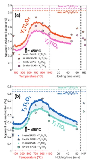
plot configuration was applied to Fig. 3, showing the evolution of the precipitates volume fraction fv
calculated from Eq. 1. The electronic contrast between the precipitates and the matrix has been calculated using 2 hypotheses on the nature of the nano-oxides: Y2Ti2O7 pyrochlore and Y2TiO5
orthorhombic (Tab. 1), the two most common precipitates observed in ODS [16,19–27]. These two apparent fv are plotted in Fig. 3 under the assumption that their composition and structure remains
constant along the heat treatment. Therefore, a mixture between both phases would result in intermediates values of the apparent fv. For visibility purpose the fv corresponding to the Y2TiO5 of
as-MA specimens were not plotted. In addition, the maximum reachable volume fraction were calculated from the alloy composition, considering Y as the limiting element (displayed in dashed lines).
Tab. 1. Properties of the nano-precipitates and matrix take into account in the SAXS apparent volume fraction calculation.
Nature Structure (space group) Mean atomic volume (×10-30 m3)
SAXS electronic density (×1030 m-3)
Fe-14Cr-1W matrix Body centered cubic
(Im-3m) 11.70 2.24 (16.829 keV) 2.24 (17.009 keV) 2.24 (17.44 keV) Y2Ti2O7 Pyrochlore (Fd-3m) 11.69 1.04 (16.829 keV) 1.02 (17.009 keV) 1.06 (17.44 keV) Y2TiO5 Orthorhombic (Pnma) 13.36 1.11 (16.829 keV) 1.08 (17.009 keV) 1.13 (17.44 keV)
The as-milled stage displays some degree of decomposition of the solid solution when compared to the unstrengthened CP specimen (Fig. 1a and 1b). These small clusters are assumed to come from the milling step. The characteristics of these clusters are visible in Fig. 2 and in Fig. 3 showing a very small initial radius and an initial volume fraction that is clearly non-zero. This finding was already observed by APT analysis on as-MA powder grains [32,43]. Kim et. al [31] and Oono et al. [32] also observed these inhomogeneous as-MA microstructures by SAXS as well as Alinger et al. [16] by SANS, who compared as-MA and unstrengthened materials. He et al. did not observe inhomogeneities until 10 min annealing at 600°C was achieved [34]. However, their maximum q-value of 2 nm-1 could explain the
impossibility to observe such small clusters. These initial clusters could arise both from fragmentation and certainly amorphization of Y2O3 until nanometric scale and/or formation of clusters of Y and O,
possibly stabilized thanks to vacancies introduced by MA [44–47]. At this initial stage, the clusters may be at the limit of validity of our interpretation model (spherical precipitates with a uniform composition and lognormal size distribution), but the presence of these very small objects is undeniable.
Surprisingly, the precipitation kinetics was found very similar between the 10°C/min to 30°C/min heating rates (Fig. 2a and 2b, see supplementary material for superimposed curves). Moreover, the ex-situ measured samples show a remarkable agreement with the in-ex-situ sequence (Fig. 2 and Fig. 3). The mean radius of precipitates starts increasing at temperatures as low as 450°C followed by a growth rate close to 1×10⁻³ nm/°C until 1100°C. This is in agreement with previous studies that already detect
precipitates after annealing at 600°C [31,32,34] and gives the onset of precipitation with an unprecedented precision. Massey et al. demonstrated a similar continuous increase of scattering between
6
200, 400 and 500°C related to the nucleation and growth of Y-Al-O precipitates, different in terms of chemistry but close in terms of manufacturing process [33]. Simultaneously, the apparent volume fraction increases. However, it is difficult to assess the reasons of this increment as this apparent volume fraction is correlated to the hypothesis made of constant precipitate structure and chemistry. These are very likely to evolve during the thermal treatment as the initial clusters are unlikely ordered nor stoichiometric after MA. Particularly, it is unlikely that the apparent volume fraction decrease observed around 900°C is caused by a dissolution of the precipitates, since the Y solubility in the matrix is extremely low at these temperatures [48,49]. This drop could be due to a decrease of the electronic density contrast between precipitates and matrix and thus a change in chemistry and/or structure of the precipitates.
During the subsequent isothermal treatment at 1100°C, the precipitates display outstanding size stability with a coarsening rate as low as 0.05 nm/h for the 10°C/min sample and even imperceptible for the 30°C/min specimen. Moreover, the final value of mean radius attained by the in-situ heat treated CP samples was found representative to the HEed or HIPed specimens (Fig. 2). Either CEA Saclay (HE-1) or PLANSEE (HE-2) milled samples display similar mean radii and apparent volume fractions, consistent with the final CP specimens (Fig. 2a and Fig. 3a). However, for an unknown reason, the HIP specimen shows a higher apparent volume fraction than the CP experiment (Fig. 3b), despite the use of the exact same powder and milling process for both.
Mean radii of precipitates were extracted form TEM images using Weka trainable segmentation algorithm of ImageJ software [50] (Fig. 2). The associated error bars correspond to the standard deviation between different analyzed areas. These measurements demonstrate a good agreement with SAXS results.
7
Fig. 2. Evolution of the mean radius of precipitates measured by SAXS data fitting and TEM measurements on CP specimens heated at 30°C/min with corresponding HE specimens (a), and
8
Fig. 3. Evolution of the apparent volume fraction of precipitates measured by SAXS and calculated for Y2Ti2O7 and Y2TiO5 type precipitates on CP specimens heated at 30°C/min with corresponding HE
specimens (a), and 10°C/min with corresponding HIP specimen (b).
Both CP specimens after annealing and HIPed samples display similar grain microstructure with a bimodal grain size distribution (Fig. 4a and c). The HE material showed elongated grains (Fig. 4e and e') certainly displaying a strong <110> texture along the extrusion direction as observed in many studies before [51,52]. Moreover, TEM micrographs show similar sizes and morphologies of the nano-oxides between both conventional processed ODS (HIP/HE) and annealed CP specimens (Fig. 4b, 4d, and 4f), in agreement with the SAXS results. Thus, the severe plastic deformation occurring during HE processing does not seem to affect the nano-precipitates size or volume fraction.
9
Fig. 4. Micrographs showing the grain microstructure by EBSD orientation maps on specimens and nano-oxides by TEM on specimens CP (a, b), HIP (c, d), and TKD orientation maps acquired in the plane orthogonal and parallel to the extrusion of the HE-2 specimen (e, e'), with TEM micrograph (f). In summary, this study demonstrates the presence of clusters in the as-milled states of ODS Fe-14Cr-1W steel. Subsequently the kinetics of precipitation has been monitored, and was found independent of the heating rate applied (10°C/min and 30°C/min). The clusters growth has been shown to start at low temperature, around 450°C. The following growth rate during heating ramp was of the order of 1×10⁻³
nm/°C and outstanding stability during isothermal holding at 1100°C has been observed with a maximum recorded growth rate of 0.05 nm/h. Precipitation in CP specimens has been shown to be representative of both HE and HIP processes, which demonstrates that the deformation induced by HE does not influence the nano-oxides properties. Finally, our results suggest an evolution of the chemistry and / or structure of the precipitates around 900°C. This will require a careful analysis which is under way by combining anomalous SAXS and atom probe tomography.
Acknowledgements
Authors strongly acknowledge Nathalie Boudet, Nils Blanc, Gilbert Chahine and Stephan Arnaud, the scientific team of D2AM-BM02 beamline of the ESRF synchrotron. Authors also thanks Michael Dadé for the acquisition and analysis of the EBSD image of the HIP specimen.
10
Supplementary Material
Supp.1. Mean radius evolution during in-situ SAXS treatment showing both 30°C/min and 10°C/min superposed curves.
Supp.2. Apparent volume fraction evolution during in-situ SAXS treatment showing both 30°C/min and 10°C/min superposed curves with the Y2Ti2O7 and Y2TiO5 hypothesis.
11
References
[1] S. Ukai, S. Ohtsuka, T. Kaito, Y. de Carlan, J. Ribis, J. Malaplate, Structural Materials for Generation IV Nuclear Reactors, Pascal Yvon, 2017.
[2] S.J. Zinkle, J.L. Boutard, D.T. Hoelzer, A. Kimura, R. Lindau, G.R. Odette, M. Rieth, L. Tan, H. Tanigawa, Nuclear Fusion 57 (2017) 92005.
[3] P. Yvon, F. Carré, Journal of Nuclear Materials 385 (2009) 217–222.
[4] P. Yvon, M.L. Flem, C. Cabet, J.L. Seran, Nuclear Engineering and Design 294 (2015) 161–169. [5] T. Tanno, M. Takeuchi, S. Ohtsuka, T. Kaito, Journal of Nuclear Materials 494 (2017) 219–226. [6] B. Gwinner, M. Auroy, D. Mas, A. Saint-Jevin, S. Pasquier-Tilliette, Journal of Nuclear Materials
428 (2012) 110–116.
[7] S. Ukai, T. Okuda, M. Fujiwara, T. Kobayashi, S. Mizuta, H. Nakashima, Journal of Nuclear Science and Technology 39 (2002) 872–879.
[8] I.-S. Kim, B.-Y. Choi, C.-Y. Kang, T. Okuda, P.J. Maziasz, K. Miyahara, ISIJ International 43 (2003) 1640–1646.
[9] Y. Yano, T. Tanno, H. Oka, S. Ohtsuka, T. Inoue, S. Kato, T. Furukawa, T. Uwaba, T. Kaito, S. Ukai, N. Oono, A. Kimura, S. Hayashi, T. Torimaru, Journal of Nuclear Materials 487 (2017) 229–237.
[10] A. Steckmeyer, V.H. Rodrigo, J.M. Gentzbittel, V. Rabeau, B. Fournier, Journal of Nuclear Materials 426 (2012) 182–188.
[11] C.R.F. Azevedo, Engineering Failure Analysis 18 (2011) 1943–1962.
[12] P. Zheng, Y. Li, J. Zhang, J. Shen, T. Nagasaka, T. Muroga, H. Abe, Materials Science and Engineering: A (2020) 139292.
[13] S.F. Li, Z.J. Zhou, P.H. Wang, H.Y. Sun, M. Wang, G.M. Zhang, Materials and Design 90 (2016) 318–329.
[14] T. Liu, H. Shen, C. Wang, W. Chou, Progress in Natural Science: Materials International 23 (2013) 434–439.
[15] M. Saber, W. Xu, L. Li, Y. Zhu, C.C. Koch, R.O. Scattergood, Journal of Nuclear Materials 452 (2014) 223–229.
[16] M.J. Alinger, G.R. Odette, D.T. Hoelzer, Acta Materialia 57 (2009) 392–406.
[17] B. Dousti, R. Mojaver, H. Reza, R. Sarraf, Journal of Alloys and Compounds 577 (2013) 409– 416.
[18] C. Suryanarayana, Progress in Materials Science 46 (2001) 1–184.
[19] J. Ribis, M.A. Thual, T. Guilbert, Y. de Carlan, A. Legris, Journal of Nuclear Materials 484 (2017) 183–192.
[20] V. Badjeck, M.G. Walls, L. Chaffron, J. Malaplate, K. March, Journal of Nuclear Materials 456 (2015) 292–301.
[21] A. Hirata, T. Fujita, Y.R. Wen, J.H. Schneibel, C.T. Liu, M.W. Chen, Nature Materials 10 (2011) 922–926.
[22] Y. Wu, J. Ciston, S. Kräemer, N. Bailey, G.R. Odette, P. Hosemann, Acta Materialia 111 (2016) 108–115.
[23] A.J. London, S. Lozano-Perez, M.P. Moody, S. Amirthapandian, B.K. Panigrahi, C.S. Sundar, C.R.M. Grovenor, Ultramicroscopy 159 (2015) 360–367.
[24] A.J. London, S. Santra, S. Amirthapandian, B.K. Panigrahi, R.M. Sarguna, S. Balaji, R. Vijay, C.S. Sundar, S. Lozano-Perez, C.R.M. Grovenor, Acta Materialia 97 (2015) 223–233.
[25] M. Ohnuma, J. Suzuki, S. Ohtsuka, S.W. Kim, T. Kaito, M. Inoue, H. Kitazawa, Acta Materialia 57 (2009) 5571–5581.
[26] M.K. Miller, C.M. Parish, Q. Li, Materials Science and Technology 29 (2013) 1174–1178. [27] A.J. London, S. Lozano-Perez, S. Santra, S. Amirthapandian, B.K. Panigrahi, C.S. Sundar, C.R.M.
Grovenor, Journal of Physics: Conference Series 522 (2014) 12028.
[28] X. Boulnat, M. Perez, D. Fabrègue, S. Cazottes, Y. de Carlan, Acta Materialia 107 (2016) 390– 403.
[29] L. Barnard, N. Cunningham, G.R. Odette, I. Szlufarska, D. Morgan, Acta Materialia 91 (2015) 340–354.
12
[31] S.W. Kim, T. Shobu, S. Ohtsuka, T. Kaito, M. Inoue, M. Ohnuma, Materials Transactions 50 (2009) 917–921.
[32] N. Oono, S. Ukai, Materials Transactions 59 (2018) 1651–1658.
[33] C.P. Massey, S.N. Dryepondt, P.D. Edmondson, M.G. Frith, K.C. Littrell, A. Kini, B. Gault, K.A. Terrani, S.J. Zinkle, Acta Materialia 166 (2019) 1–17.
[34] P. He, P. Gao, Q. Tian, J. Lv, W. Yao, Materials Letters 209 (2017) 535–538.
[35] A. Deschamps, F.D. Geuser, J. Malaplate, D. Sornin, Journal of Nuclear Materials 482 (2016) 83– 87.
[36] A. Deschamps, F.D. Geuser, Journal of Applied Crystallography 44 (2011) 343–352. [37] V. Gerold, G. Kostorz, Journal of Applied Crystallography 11 (1978) 376–404.
[38] M. Dumont, L. Commin, I. Morfin, F. Degeuser, F. Legendre, P. Maugis, Materials Characterization 87 (2014) 138–142.
[39] M. Klimiankou, R. Lindau, A. Möslang, Journal of Nuclear Materials 367–370 (2007) 173–178. [40] Q. Zhao, Z. Ma, L. Yu, H. Li, C. Liu, C. Li, Y. Liu, Journal of Materials Science & Technology
35 (2019) 1064–1073.
[41] H. Sakasegawa, L. Chaffron, F. Legendre, L. Boulanger, T. Cozzika, M. Brocq, Y.D. Carlan, Journal of Nuclear Materials 384 (2009) 115–118.
[42] P. He, M. Klimenkov, R. Lindau, A. Möslang, Journal of Nuclear Materials 428 (2012) 131–138. [43] C.A. Williams, D. Haley, E.A. Marquis, G.D.W. Smith, M.P. Moody, Ultramicroscopy 132 (2013)
271–278.
[44] A. Gopejenko, Y.F. Zhukovskii, P.V. Vladimirov, E.A. Kotomin, A. Möslang, Journal of Nuclear Materials 406 (2010) 345–350.
[45] D. Murali, B.K. Panigrahi, M.C. Valsakumar, S. Chandra, C.S. Sundar, B. Raj, Journal of Nuclear Materials 403 (2010) 113–116.
[46] A. Claisse, P. Olsson, Nuclear Instruments and Methods in Physics Research, Section B: Beam Interactions with Materials and Atoms 303 (2013) 18–22.
[47] M.K. Miller, C.L. Fu, M. Krcmar, D.T. Hoelzer, C.T. Liu, Frontiers of Materials Science in China 3 (2009) 9–14.
[48] M.S. Farkas, A.A. Bauer, THE SOLID SOLUBILITY AND CONSTITUTION OF YTTRIUM IN IRON-20 TO 40 W/o CHROMIUM ALLOYS, 1959.
[49] S.G. Epstein, A.A. Bauer, R.F. Dickerson, SOLUBILITY LIMITS OF YTTRIUM AND THE LANTHANIDE RARE-EARTH ELEMENTS IN CHROMIUM AND CHROMIUM-IRON ALLOYS, 1959.
[50] I. Arganda-Carreras, V. Kaynig, C. Rueden, K.W. Eliceiri, J. Schindelin, A. Cardona, H. Sebastian Seung, Bioinformatics 33 (2017) 2424–2426.
[51] M. Serrano, M. Hernández-Mayoral, A. García-Junceda, Journal of Nuclear Materials 428 (2012) 103–109.