HAL Id: cea-02614127
https://hal-cea.archives-ouvertes.fr/cea-02614127
Submitted on 20 May 2020HAL is a multi-disciplinary open access archive for the deposit and dissemination of sci-entific research documents, whether they are pub-lished or not. The documents may come from teaching and research institutions in France or abroad, or from public or private research centers.
L’archive ouverte pluridisciplinaire HAL, est destinée au dépôt et à la diffusion de documents scientifiques de niveau recherche, publiés ou non, émanant des établissements d’enseignement et de recherche français ou étrangers, des laboratoires publics ou privés.
Simplified thermohydraulic criteria for a comparison of
the accidental behaviour of GEN IV nuclear reactors
and of PWRs
F Bertrand, N. Marie, A. Bachrata, J.-B. Droin, X. Manchon
To cite this version:
F Bertrand, N. Marie, A. Bachrata, J.-B. Droin, X. Manchon. Simplified thermohydraulic criteria for a comparison of the accidental behaviour of GEN IV nuclear reactors and of PWRs. NURETH 18 -The 18th International Topical Meeting on Nuclear Reactor -Thermal Hydraulic, Aug 2019, Portland, United States. �cea-02614127�
The 18th International Topical Meeting on Nuclear Reactor Thermal Hydraulics (NURETH-18) Log Number:
Marriott Portland Downtown Waterfront, Portland, OR, USA, August 18-22, 2019
SIMPLIFIED THERMOHYDRAULIC CRITERIA FOR A COMPARISON
OF THE ACCIDENTAL BEHAVIOUR OF GEN IV NUCLEAR REACTORS
AND OF PWRS
F. Bertrand, N. Marie, A. Bachrata, J.B. Droin, X. Manchon
CEA, DEN, DER, F-13108 Saint-Paul-lez-Durance, France
Corresponding author: frederic.bertrand@cea.fr, Tel: +33 (0) 4 42 25 30 79
ABSTRACT
A comparison of 3 Generation IV reactor concepts between them and with a PWR of 2nd generation is presented in this paper. The 3 Gen IV reactor concepts considered have been studied at CEA and are briefly presented in the first part of the paper: SFR of 1500 MWth, GFR of 2400 MWth and VHTR of 600 MWth. In order to perform this comparison, some simple common criteria related to accidental behavior of the reactors have been developed. The first kind of criteria are aimed at assessing the main physical thresholds to exceed in order to have a core degradation: phase changes of coolant and of core materials (including the effect of chemical reactions) for the various reactor concepts considered. The second set of criteria deals with kinetics aspects of the accident. On the basis of core power (after scram and without scram), on the coolant inventory and on the reactor capability to be passively cooled, the heating rate of the coolant and of the core materials are assed thanks to simplified energy balances presented in the paper. As a result, for each reactor concept, the time to reach the physical thresholds defined above is assessed. A third set of criteria deals with core features and are aimed at assessing the possible reactivity insertion that withstands each concept up to core melting and the associated expected power peaks in case of coolant voiding/depressurization and in case of core materials relocation. Finally, a last criterion set deals with the assessment of the possibility to challenge physical barriers confining fission products. These criteria deal with the risk of barrier loadings due to coolant and core material vaporization depending on the features of the coolant and on the operating point of each reactor concept. In the last part of the paper, a synthesis is made in order to underline the weak and strong points of each of the reactor concept investigated in terms of severe accident prevention and mitigation.
KEYWORDS
Simplified criteria, Reactor accident behavior, SFR, GFR, VHTR, PWR, prevention, mitigation 1. INTRODUCTION
Some criteria enabling to compare reactor concepts between each other are proposed in this paper. This comparison relies on the expected behavior of the reactor considered in case of accident. The objective of these criteria is to provide information of high interest for the reactor design robustness when facing an accident resulting from any family of initiating events. Indeed, the criteria are based on reactor features associated to coolant features, core features and the expected loadings on physical barriers of the reactor confining fission products. As a result, they are very simple and enable, when designing a reactor, to have a first idea of its accidental behavior without making extensive safety studies since they rely on order of magnitudes. Therefore they could be used either to help designers very early in the design process, that is, when the reactor components are not all decided neither integrated. Alternatively, they could help to
understand at a glimpse strength and weaknesses of reactor concepts from a synthetic point of view (see Sections 3 and 4 of this paper). Prior to introduce and to apply the simplified criteria proposed in this paper, a succinct presentation of the investigated reactor concepts is provided in section 2. In section 3 of the paper those criteria are introduced and explained. In the same section, they are applied to 3 generation IV reactor concepts investigated at CEA as well as to a PWR which consists in a reference concept whose features are widely known. Finally, in section 4, the main highlights brought by the synthesis of the analysis done with the criteria are presented in terms of prevention of severe accidents capability and in terms of mitigation.
2. OVERVIEW OF THE CONSIDERED REACTOR CONCEPTS
The reactor concepts considered in order to quantify the criteria proposed in this paper are roughly described in this section. Only the main features required to understand the criteria background are presented here. For further elements, some references are mentioned in the section.
2.1. VHTR (very high temperature reactor)
The reactor concept considered here applies the block type (prismatic) core design, in which, the coated particle fuel, a common feature of all VHTRs, is contained within prismatic graphite blocks that are arranged to form an annular core geometry [1]. The core is sized to produce 600 MW of thermal power, with a targeted outlet temperature of 950°C for a core inlet temperature of 400°C. Helium is used a the primary heat coolant at 47 bars with a nominal flow rate of 210 kg/s. The thermal power produced by the core is transferred to a secondary circuit by means of an intermediate heat exchanger IHX (Fig. 1).
Figure 1. VHTR core and vessel system arrangement [1]
The advantages of the VHTR come from its ceramic fuel system (UO2 particles coated with SiC insuring
close confinement of radionuclides) and a large graphite moderator mass. These features provide a high temperature operation associated to the elimination of the possibility of fuel damage [1] thanks to the ability of the core to store the decay heat and then, to release it through radiative and conductive exchanges. For reaching such a target, the power density of the core is about 5 MW/m3. The core materials have a large
2.2. GFR (gas-cooled fast reactor)
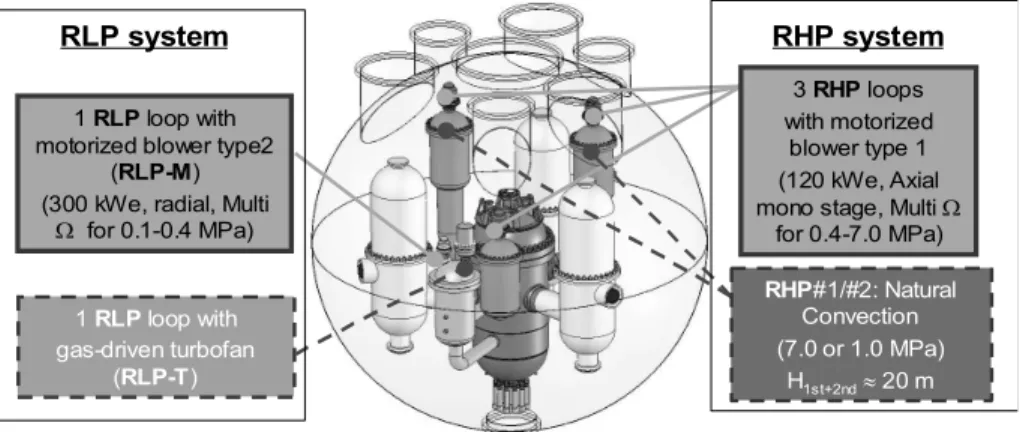
The gas-cooled fast reactor concept considered here is the CEA GFR2400 [2]. The GFR combines the benefits of a fast spectrum and of a high temperature (~ 850°C at the core outlet and 400°C at the core inlet). The detailed GFR design is presented for instance in [3], therefore only the features useful for the understanding of this paper are presented here. The operating point of the 3-loops reactor at full nominal power enables to convert the 2400 MWth delivered by the core in 1100 MWe, partly by secondary circuit turbomachineries (auxiliary alternators: 3 x 130 MWe) and partly by a steam turbine (main alternator: 1 x 730 MWe) settled in the ternary circuit. The primary system arrangement (Fig. 2) includes the reactor vessel, the 3 main primary loops (PCS loops) and their heat exchangers (IHX) as well as the DHR loops permitting to cool the core in accidental situations. Actually, there are three loops, so-called, reactor high pressure cooling system (RHP) and a loop for the low pressure situations (RLP). The secondary side of the DHR loops, is filled with water pressurized at 10 bars. Moreover, all the previous components are enclosed in a close containment (CC) which keeps the primary inventory in case of loss of coolant accident (LOCA). The CC is filled with nitrogen at 1 bar under normal operation.
Figure 2. arrangement of the GFR primary circuit components (RHP: high pressure DHR loops; RLP: low pressure DHR loops)
The plate type fuel element is an innovative concept based on two ceramic plates which enclose a honeycomb structure containing the fuel cylindrical pellets [2]. The plate consists in a uranium–plutonium carbide, (UPuC) for pellets, composite SiC-SiCf for thin plates (clad) and SiC for the honeycomb structure. At the hot spot of the core, the clad temperature is equal to 1000°C and the fuel temperature is about 1380°C in nominal conditions for a core flow rate of 1000 kg/s delivered at 70 bars. The power density is equal to 91 MW/m3. The coolant being largely transparent to neutrons [2]: the voiding effect is lower than 1$ without a threshold effect due to a phase change possibly affecting liquid coolants. Considering the power density of the GFR core and its low thermal inertia and that of its coolant as well, the decay heat removal relies on a gas circulation (natural circulation as far as possible) across the core but not on provisions based on thermal inertia plus conduction/radiation.
2.3. SFR (sodium cooled fast reactor)
ASTRID was designed to fulfil the Gen IV criteria in terms of safety, sustainability, economy and proliferation resistance [4]. This reactor consists in a 1500 MWth SFR pool type reactor of about 600 MWe that is an integrated technology prototype designed for industrial-scale demonstration of 4th generation
SFR safety and operation. Fuel type is oxide. The ASTRID pool type primary circuit includes three primary
3 RHP loops with motorized
blower type 1 (120 kWe, Axial mono stage, Multi
for 0.4-7.0 MPa) RHP#1/#2: Natural Convection (7.0 or 1.0 MPa) H1st+2nd 20 m 1 RLP loop with gas-driven turbofan (RLP-T) 1 RLP loop with motorized blower type2
(RLP-M) (300 kWe, radial, Multi
for 0.1-0.4 MPa)
pumps and four secondary loops, each one being equipped with an intermediate heat exchanger (IHX) immersed in the reactor vessel (Fig. 3).
Figure 3. Primary system arrangement for ASTRID .
Each secondary loop delivers a fourth of the core power (375 MWth) to steam generators or to sodium/gas heat exchangers. The nominal reactor operating point is featured by a core flow rate equal to 7900 kg/s, a core inlet and outlet temperature respectively equal to 400°C and 550°C. The power density is close to 250 MW/m3. The primary vessel is not pressurized and only the hydrostatic pressure and the pump head
contribute to the primary pressure.
2.4. PWR (pressurized water-cooled reactor)
The reactor concept considered here as a reference existing concept deals with the 1300 MWe PWR whose thermal power is about 3800 MW. The primary flow rate is about 23 t/s delivered at a pressure of 155 bars through 4 loops (Fig. 4). The core inlet temperature is equal to 293 °C and the core outlet temperature is equal to 329 °C. The fuel UO2 or MOx pins are cladded with Zircaloy. Finally, the water mass inventory in
the primary circuit is about 280 t [5].
3. ELABORATION AND PRESENTATION OF SIMPLIFIED CRITERIA
The first part of this section is devoted to the background of the proposed criteria and to the methodology adopted for their definition. In a second part of this section, the physical meaning and the expression of the criteria are provided.
3.1. Criteria elaboration approach
The criteria presented here have been elaborated in order to assess the capability of a reactor concept to prevent a severe accident (featured by a core melting situation that could lead or that can be associated to a containment failure) and its capability to mitigate it. More specifically, the occurrence of a severe accident always results from a disequilibrium between the power (P (W)) released into the nuclear fuel and the flow rate (Q (kg/s) crossing the core to cool this fuel. When this ratio P/Q increases, the coolant begins to be overheated and so does the fuel, the cladding and other structure materials located into the core. During this temperature escalation occurring in the core, some physical thresholds can be reached and then the range of the accident consequences can become more and more severe. Another important issue is to know the margin existing between the nominal reactor operation value of each parameter of interest for the accident
evolution and the aforementioned thresholds. For instance, the difference between the coolant temperature at the core outlet in nominal operation and this temperature when it boils, provides such a margin. Finally, since an accident occurs through a transient of the reactor, the dynamic evolution of each parameter of interest is very important in order to assess the time required to reach the thresholds. Regarding the ability of a reactor concept to mitigate severe accident consequences, some criteria related to source term and to the risk of loadings of each successive physical barriers confining radionuclides are proposed.
Figure 4: Sketch of the primary vessel of a 1300 MWe PWR [5]
3.2. Criteria related to thermalhydraulic thresholds
The first set of criteria deals with the phase change temperature of the coolant and of the core materials (fuel and its cladding). Indeed, when the coolant boils, there is a threshold effect on the heat exchange coefficient between the cladding and the coolant. In the same way, when liquid or vapor phases appear into the core materials, there is a loss of core geometry that can make the degraded core materials no more coolable. One last criterion deals with the capability to cool the core in natural circulation depending on the coolant and on the reactor design. The natural circulation requires a temperature difference Tbetween the hot spot of a reactor primary fluid flow path and its cold spot that induces a density difference kg/m3)By considering respectively, k and the average friction coefficient and the density of the
coolant in the circuit, one can write by equalizing the driven pressure of the natural circulation and the overall pressure drop in the loop:
∆ρ. g. h = 𝑘ρ𝑣 (1)
where g is the gravity acceleration (m/s2) and v the average fluid velocity in the circuit (m/s). By assuming
the Boussinesq approximation, and by introducing the thermal expansion coefficient of the fluid (K-1),
equation (1) becomes:
β. ∆T. g. h = 𝑘𝑣 (2)
Moreover, Presi being the decay heat (W) and S the average cross-section of the fluid (m2) into the loop and
Cp the heat capacity of the coolant at its average temperature (J/kg/K), one can express in a steady state, the
power as:
Finally by expressing the velocity v thanks to equation (2) and injecting this expression into equation (3), the ∆T required for a natural circulation can be expressed as:
∆T = .
. . . (4)
By considering the first parenthesis of the right side of equation (4), one can call it A thus gathering parameters related to the loop design. Doing this, we just have in relation (5), the expression of the temperature difference required to operate a natural circulation flow versus the coolant properties and the driving height of the flow. ∆T = 𝐴. . . . (5)
By using equation 5, and by assessing the parameter (𝜌 . 𝐶 . 𝛽)1/3 related to the coolant, one can derive values presented in Table 2 for nominal conditions of the 4 concepts and the implication associated to the driving height and the fluid heating in the circuit. The proposed criteria are presented in Table 1 for each reactor concept considered in this paper. Table 1. Coolant and core material threshold and natural circulation capability for various concepts Threshold/Concept VHTR GFR SFR PWR Coolant boiling temperature (°C) - - ~ 900 ~340 (15 MPa) Margin to boiling* (°C) - - ~425°C ~0 (pressurized) Order of magnitude of HTC**** (W/(m2.K)) -Nominal -Vapour/Low pressure natural circulation ~ 2.10 2 -/~20 ~3.10 2 -/~30 ~10 5 ~102/~103 ~ 104 ~102/~10 Fuel melting/sublim. temperature**(°C) ~ 2800°C ~ 2200°C ~2700°C ~2800°C Margin to fuel melting (°C) ~1600°C ~1000°C ~700°C ~1200°C Clad temperature loss of integrity (°C) Clad melting temperature (°C) 2700°C(sub) >2000°C ~ 1850°C 2700°C(sub) ~ 900°C ~1400°C ~1800°C ~850°C Margin to clad loss of integrity (°C) ~900°C ~1000°C ~350°C ~ 500°C Clad boiling temperature (°C) Fuel boiling temperature (°C) ~3400°C 2700°C >3000°C 2700°C ~2900°C ~3300°C ~4400°C ~3400°C Margin to clad boiling (°C) Margin to fuel boiling (°C) ~2000°C ~2000°C ~1700°C ~1700°C ~2000°C ~1500°C ~3000°C ~1500°C Natural convection capability*** poor poor medium high *: the margin is considered from nominal operating point **: liquefaction due to chemical interactions are not considered in this criterion but in the cladding loss of integrity criterion ***: the criterion leading to the assessment of the natural convection capability is explained below. ****: convective HTC Table 2. Natural circulation criteria for various concepts (temperature difference between hot and cold spot of the circuit is taken as a reference for a PWR) (𝜌 . 𝐶 . 𝛽)1/3 ∆T/∆Tpwr VHTR ~ 50 ~200 GFR ~ 90 ~ 100 SFR ~ 700 ~ 15 PWR ~ 10000 1
The analysis of data presented in Tables 1 and 2 indicate that the liquid coolants are affected by threshold effects on the heat transfer coefficient (HTC) when they boil. The margin to boiling is much more larger for SFR since for PWR, it is necessary to keep the primary circuit under pressure to keep a margin to boiling. Therefore, the degradation of the HTC can be larger for PWRs than for SFRs, since the HTC can be degraded by phase change but by the loss of primary pressure as well. The loss of primary pressure leads as well to HTC decrease for gas reactor concepts, especially if they operate in natural circulation of the primary circuit. Moreover, the margin to material melting and to fuel element loss of integrity is comfortable for all the reactor concepts. The lowest margin to the loss of integrity deals with the SFR claddings. Table 1 exhibits the capability associated to various coolant to operate in natural circulation and Table 2 enables to quantify the expected temperature difference depending on the coolant. These values of T are provided for the same driven height and the same circuit flow impedance. So it means that for a VHTR, natural convection is very difficult to valorize. This is the reason why, the provisions retained to cool the core for this concept do not rely on natural convection but on conduction and radiative heat exchanges. Regarding the GFR, the natural circulation is used for core cooling, but efforts have been made to reduce the loop pressure drop and a large driving height associated to a large is necessary, even after scram. Finally, it can be kept in mind that natural circulation is very easy for PWRs providing that the hydraulic flow path is kept. This flow path is more obvious for SFRs since core and DHR heat exchangers are immersed into the vessel.
3.3. Criteria related to the kinetic evolution of the thermalhydraulic parameters of concepts
The first family of criteria presented above were aimed at assessing the various threshold whose reach leads to change the range of an accident consequences. In order to go deeper in our comparative analysis, some criteria dealing with the evolution dynamics of the reactor parameters up to the reach of the criteria are proposed. Basically, the heating of the core materials without any cooling has been assessed in nominal and residual power by taking into account or not the primary coolant inertia (inertia of the primary circuit structures are not taken into account). The simple energy balances used are presented hereafter and the main concept features used are provided in Table 3.
Table 3. Reactor concept features related to heating dynamics
Parameter/Concept VHTR GFR SFR PWR
Power Density, Pvol (MW/m3) ~ 5 ~ 100 ~250 ~ 100
Total thermal power, Ptot (MW) 600 2400 1500 3800
Coolant mass inventory, mcool (t) 1 7 2000 280
The heating rate of the whole primary circuit is assessed by considering that it is governed by the coolant inertia (equation (6)) where Presi is the residual power of the core (W), mcool the coolant mass inventory (kg),
Cp the heat capacity of the coolant and Tcool the average coolant temperature:
= (6)
With another energy balance, the core temperature increase with no flow rate can be roughly assessed with equation (7):
=
(∑ ) (7)
Where Tcore is an average core material temperature, Pvol, the core power density (MW/m3),
the heat capacity (J/kg/K) of material i and Xi the volumic fraction of material i. Moreover, by considering
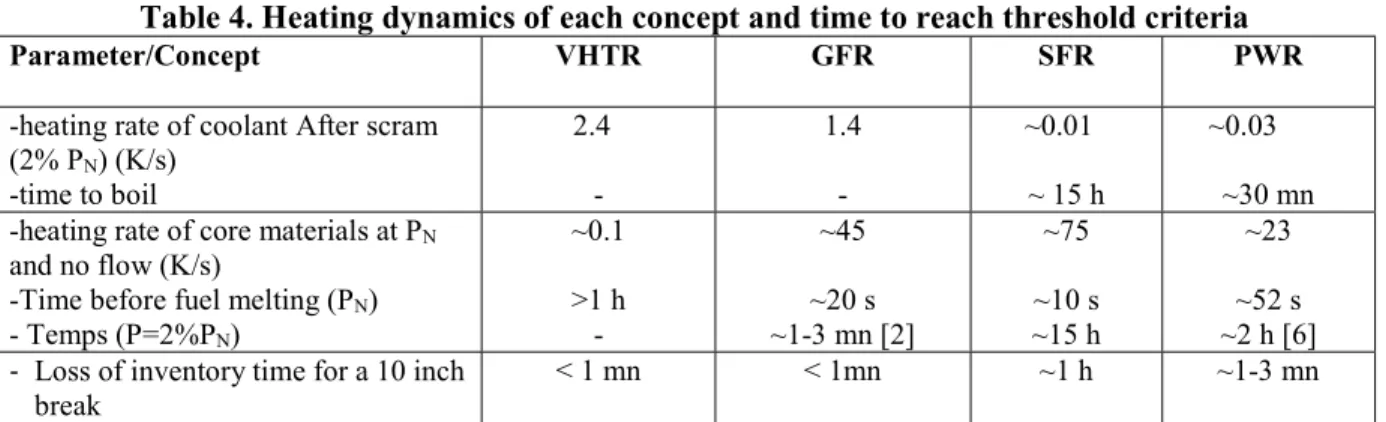
the primary pressure of the various reactor concepts and a postulated break size in the circuit, an order of magnitude of the circuit depressurization or draining (for SFR) time is assessed by simply taking into account the coolant inventory and the pressure difference between the reactor primary circuit and its surrounding medium. From Table 3 and the aforementioned considerations, one can deduce the orders of magnitude presented in Table 4.
Table 4. Heating dynamics of each concept and time to reach threshold criteria
Parameter/Concept VHTR GFR SFR PWR
-heating rate of coolant After scram (2% PN) (K/s) -time to boil 2.4 - 1.4 - ~0.01 ~ 15 h ~0.03 ~30 mn -heating rate of core materials at PN
and no flow (K/s)
-Time before fuel melting (PN)
- Temps (P=2%PN) ~0.1 >1 h - ~45 ~20 s ~1-3 mn [2] ~75 ~10 s ~15 h ~23 ~52 s ~2 h [6] - Loss of inventory time for a 10 inch
break
< 1 mn < 1mn ~1 h ~1-3 mn * :here it is considered that the steam generator inertia can slow down the heating because the primary and secondary circuit are strongly coupled in such black-out like transient and the PWR concept can take benefit of a large secondary side inventory assumed here to be equal to the primary one.
The analysis of Table 4 confirms that gas-cooled reactors do not have any thermal inertia in the coolant and enables to understand why the gas concepts are designed with ceramic claddings. Nevertheless, the design provisions retained to cool the core in accidental situations are different when considering the VHTR and the GFR. Owing to its power density, the latter relies on coolant circulation into the core thanks to active means and thanks to provisions aiming at limiting the possible depressurization (CC and nitrogen injection [2]). In the VHTR case, the decay heat removal relies on passive devices thanks to a large core inertia and a low power density. Pool type SFR benefits from a large coolant thermal inertia but their large power density make them sensitive to loss of flow with a large core power (like ULOFA, unprotected loss of flow [4]). Finally, PWR concepts requires specific design options (safety injection systems, accumulators) consisting in a lot of active systems in order to prevent core melting in case of LOCA. However, this loss of coolant enables to extract energy from the primary system and to delay the core melting [7].
3.4. Criteria related to neutron physics behavior of the core concept
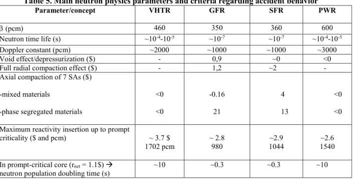
Table 5 gathers some parameters related to the core behavior of each concept in case of reactivity insertion. Two kind of concepts are clearly discriminated by these parameters, namely the thermal and the fast neutron spectra concepts. The fraction of delayed neutron pcm) and the time life Λ(s) of prompt neutrons enable to assess the power increase caused by a given reactivity insertion for the various reactor concepts. By roughly assuming a reactor kinetics governed by prompt neutrons without any effect of neutrons precursor, the power evolution can be assumed by:
~ 𝑃 (8)
Where P (W) is the core power and r (pcm) the core reactivity. So it can be seen that the power increases like an exponential function of the opposite of and of the invert of the lifetime of neutrons. The Doppler constant Kd (pcm), the voiding effect, as well as the radial and axial compaction effects are also of major
importance. Finally, those physical parameters enable to derive the maximal reactivity that can be inserted into each core concept without leading the core to prompt criticality. Here it is considered that the reach of the prompt criticality leads to fuel melting which is a reasonable assumption considering the large power
increase when a core is prompt-critical. Moreover, in case of fast reactivity insertion, only the Doppler effect can mitigate the power increase because this effect has a very short time response compared to the other reactivity feedbacks. So, one criteria is proposed to assess the margin of a core concept to prompt-criticality as rmax (pcm) and can be expressed:
𝑟 = 𝛽 + 𝐾 ln ( ) (9)
Where Tmelt is the fuel melting temperature (K) and Tnom is the fuel average nominal temperature (K). The
analysis of the parameters and criteria (margin to prompt-criticality and neutron population doubling time) provided in Table 5 enables to show that the fast reactor cores are more sensitive to reactivity insertion: the margin to prompt-criticality is lower for fast neutrons reactors than for the VHTR and PWR. However, as the GFR and SFR cores are operated in a configuration that is not the most reactive, a density decrease of coolant in the positive void worth region of GFR and SFR cores can induce a reactivity increase. A reactivity increase would also occur in case of fuel compaction (radial and axial). In case of thermal spectra concepts, such a compaction would lead to a decrease of the average volume fraction of moderator and therefore to a reactivity decrease. However, thanks to the CFV core concept implemented in ASTRID [8], the reactivity evolution expected during the primary phase1 of a severe accident is comparable for the GFR
and for the SFR. Regarding the axial compaction that occurs later in the accident course, the SFR design can incorporate some fuel discharge devices in order to limit the reactivity insertion like in the French SFR project [8] or in the Japanese JSFR project [9]. Finally, even if the VHTR and the PWR concepts have more margin to prompt-criticality and slower power increase in case of reactivity insertion than GFR and SFR concepts, the possibility of initiating events leading to reactivity insertion should be investigated with care because these concepts are pressurized (risk of rod ejection) and the PWR includes dissolved boron to control the reactivity (the concentration of this latter should be controlled carefully to avoid pure water core ingress).
Table 5. Main neutron physics parameters and criteria regarding accident behavior
Parameter/concept VHTR GFR SFR PWR
(pcm) 460 350 360 600
Neutron time life (s) ~10-4-10-5 ~10-7 ~10-7 ~10-4-10-5
Doppler constant (pcm) ~2000 ~1000 ~1000 ~3000
Void effect/depressurization ($) - 0,9 ~0 <0 Full radial compaction effect ($) - 1,2 ~2 - Axial compaction of 7 SAs ($)
-mixed materials
-phase segregated materials
<0 <0 -0.16 21 4 13 <0 <0 Maximum reactivity insertion up to prompt
criticality ($ and pcm) ~ 3.7 $
1702 pcm ~ 2.8 980 1044 ~2.9 1540 ~2.6 In prompt-critical core (rnet = 1.1$)
neutron population doubling time (s)
~10 ~0.3 ~0.3 ~10
1 the primary phase of a fast neutron reactor severe accident deals with the beginning of the core degradation during
3.5. Criteria related to the loadings of physical barriers and confinement of radionuclides
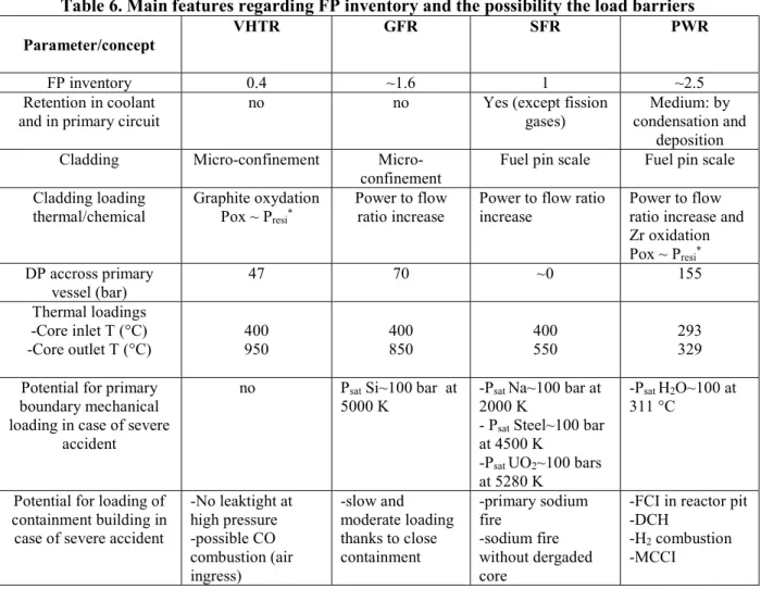
This section deals with the analysis of the various features of the reactor concepts, important for keeping the integrity of the overall confinement function. So the first one is the possibility to trap in the coolant some of the fission products (FP) playing a role in the source term. The second one deals to the possibility to load the successive physical barriers interposed between FPs and environment by considering the thermophysical and chemical properties of the coolant and of the core materials. Finally, it has been considered that the radionuclides inventory depends directly on the core power and it has been normalized to ASTRID reactor. No consideration has been taken into account regarding the spent fuel storage of the concepts. The analysis of Table 6 traduces the effect of size on the magnitude of the source-term to be expected in case of unmitigated severe accident as well as of the coolant and primary circuit capability to catch the FP. The micro-confinement strategy adopted in the gas-cooled reactors enables to lower the FP inventory in case of local loss of integrity of the cladding. Regarding the fuel element boundary loading (cladding), fast reactor are more likely to induce loadings due to a loss of control of the power to flow ratio in the SAs since the cladding are highly pressurized and since the concepts are sensitive to reactivity insertion and to unprotected transients (Tab. 4). On the other hand, the thermal spectra concepts favor the likelihood of oxidation by air or by steam because in LOCA, there is no physical barrier between oxidizing compounds and the fuel elements (Tab. 6). Regarding the possible thermal loading of the primary boundary, thermal shocks are concerns for SFR and PWR due to liquid coolants large HTC.
Table 6. Main features regarding FP inventory and the possibility the load barriers Parameter/concept
VHTR GFR SFR PWR
FP inventory 0.4 ~1.6 1 ~2.5
Retention in coolant and in primary circuit
no no Yes (except fission gases)
Medium: by condensation and
deposition Cladding Micro-confinement
Micro-confinement Fuel pin scale Fuel pin scale Cladding loading thermal/chemical Graphite oxydation Pox ~ Presi* Power to flow ratio increase
Power to flow ratio increase
Power to flow ratio increase and Zr oxidation Pox ~ Presi* DP accross primary vessel (bar) 47 70 ~0 155 Thermal loadings -Core inlet T (°C) -Core outlet T (°C) 400 950 400 850 400 550 293 329 Potential for primary
boundary mechanical loading in case of severe
accident
no Psat Si~100 bar at
5000 K -P2000 K sat Na~100 bar at - Psat Steel~100 bar
at 4500 K
-Psat UO2~100 bars
at 5280 K
-Psat H2O~100 at
311 °C
Potential for loading of containment building in
case of severe accident
-No leaktight at high pressure -possible CO combustion (air ingress) -slow and moderate loading thanks to close containment -primary sodium fire -sodium fire without dergaded core
-FCI in reactor pit -DCH
-H2 combustion
-MCCI *Graphite and zircaloy oxidation power is of the same order of magnitude as the decay heat
Nevertheless, the high gas temperature implies to adopt specific design options like cross-duct in primary legs (Fig. 1 and 2) in order to not expose the hot legs to a high pressure difference from inside to outside and like a top-down gas flow (VHTR) into the core associated to a control of the hot gas jet impingement in the lower plenum of the primary vessel [10]. Moreover, in the gas-cooled concept, there is not possibility to have explosive vaporization due to a large enthalpy release into the fuel and due to its mixing with coolant. Finally PWR concept is the more likely to induce core-melting situations leading to containment building large loadings. This is why for this concept, some design provisions are foreseen in recent concepts like EPR to practically eliminate core melting under pressure (depressurization strategy versus FCI and DCH), to cool corium in order to prevent MMCI (core catcher) and to mitigate hydrogen combustion effects (hydrogen recombiners) [11]. For the GFR concept, the long-term corium cooling is still to be investigated. Finally, in the GEN IV concepts the provisions to foresee regarding containment building are less demanding than for a PWR.
4. SYNTHESIS
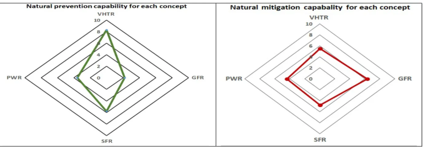
Various parameters and criteria have been presented in section 3. In this section, an attempt to rank the concepts according to the elements presented in the previous section is presented in a very rough way. However, the detailed conclusions of the analysis have been already provided in section 3 but they are related to various aspects of the accidental behavior and of the design. Therefore, in this section there is an attempt to aggregate various criteria and concept features according to accident sequences when considering prevention and according to barrier loadings and FP release when considering mitigation. Regarding prevention capability, a different criterion has been associated to each sequence family owing to its physical effect:
- heating dynamics due to decay heat for LOHS; - core material heating for (U)LOFA/LOCA;
- power increase rate and margin to prompt-criticality for (U)TOP.
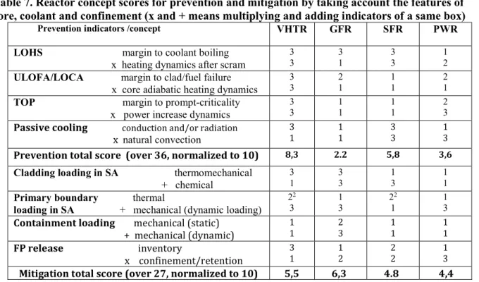
A margin to an unwilling effect and a dynamics to fully consume this margin are considered and scored from 1 to 3 for each accident family of interest. For instance, a large margin to coolant boiling scores 3 because it is favorable for core melting prevention (low scores 1 and intermediate 2) whereas high coolant heating dynamics scores 1 and low coolant heating dynamics scores 3. Typically, when shifting from one score point related to dynamics means dividing/multiplying this dynamics by an order of magnitude. By multiplying both scores for each accident family (the 2 indicator are therefore combined because thay are associated to the same accident) and by summing the scores of each concept for all accident families, one can established an order of magnitude of its prevention capability (Tab. 7 and Fig. 5). Moreover, a generic criterion based on passive cooling capability is considered. A similar approach is proposed in order to rank the potential of loadings of each barrier in case of severe accident but the 2 scores of each box dedicated to loadings are added since they are not related to the same kind of scenario. The 2 scores of the box dedicated to the releases are multiplied with each other because it is necessary to combine the potential retention capability to the order of magnitude of the FP inventory in order to assess the potential for source term. The kind of loadings are mechanical, thermal and chemical. In the same way, an overall indicator is provided by summing the score of each line of a column related to a concept. This indicator enables to compare the mitigation capability of the various concepts.
The scores proposed here should be considered with care since they mainly refer to the intrinsic natural behavior of the concepts without respect of the prevention and mitigation provisions that are implemented in the various design. Consequently, they are not aimed at assessing the actual safety level of a reactor, but they can help to orientate the pre-conceptual design process. Indeed they can enable to assess what provisions should be implemented in the concept to improve the natural behavior of the reactor in terms of prevention and of mitigation actions. A low score in prevention
means that given a core and a coolant and confinement options, one should prevent core melting with a lot of safety systems involved in cooling and reactivity control. In the case of a good score, its means that for a given design, it can be relied on the good intrinsic features of the reactor to prevent core melting, without a lot of safety provisions. The same trend is to underline regarding mitigation scores. As an illustration, by considering the PWR mitigation score, it is expected that the possible consequences of a severe accident should be mitigated thanks to addition of mitigation devices. Actually, this addition has been done, in particular for the EPR concept [11] (core catcher, primary circuit depressurization devices, etc.). Thus, the actual mitigation score of PWRs when considering the implemented mitigation provisions is much more higher than assessed in Table 7.
Conversely, some mitigation provisions implemented in the SFR concept, like the inner-vessel core catcher relying on dedicated devices included in the design have been taken into account in Table 7 for thermal primary boundary protection. Additionally, due to the time constant and the potential for dynamic loadings in a SFR concept, the obtained score for mitigation could be difficult to improve a lot. Regarding prevention, SFR capability is higher than pressurized concepts with a same power density because it is not pressurized, has large thermal inertia and margin to boiling combined to a good capability to operate in natural convection. GFR, combines a poor cooling capability with a high power density that penalizes it for core melting prevention but since there is a very low potential for liquid explosive vaporization in the reactor and an expected good retention factor, it is not bad scored for mitigation. Finally, the passivity level of the VHTR due to its large thermal inertia and its thermal spectrum eliminating power excursion issues, provides him a good score for prevention. VHTR mitigation score is comparable to those of other concepts because if some fuel particles failure occurs (for instance, due to uncontrolled graphite oxidation), the retention capability of the escaping FP is low because there is only 2 physical tight barriers. Figure 5 summarizes on the same graph the scores of various concepts regarding core melting prevention and severe accident mitigation.
Table 7. Reactor concept scores for prevention and mitigation by taking account the features of core, coolant and confinement (x and + means multiplying and adding indicators of a same box)
Prevention indicators /concept VHTR GFR SFR PWR
LOHS margin to coolant boiling x heating dynamics after scram
3 3 3 1 3 3 1 2
ULOFA/LOCA margin to clad/fuel failure x core adiabatic heating dynamics
3
3 2 1 1 1 2 1
TOP margin to prompt-criticality x power increase dynamics
3
3 1 1 1 1 2 3
Passive cooling conduction and/or radiation
x natural convection
3
1 1 1 3 3 1 3
Prevention total score (over 36, normalized to 10) 8,3 2.2 5,8 3,6
Cladding loading in SA thermomechanical + chemical 3 1 3 3 1 3 1 1
Primary boundary thermal
loading in SA + mechanical (dynamic loading)
22 3 1 3 22 1 1 3
Containment loading mechanical (static) + mechanical (dynamic) 1 1 2 3 1 1 1 1 FP release inventory x confinement/retention 3 1 1 2 2 2 1 3
Mitigation total score (over 27, normalized to 10) 5,5 6,3 4.8 4,4
2 Here, since the fuel of concept coud not largely melt nor enter in contact with vessel, the thermal loading is only
intermediate due to the possibility to have a transient with failure of degraded operating of reactor cavity cooling system or of in-vessel DHR system (for SFR) that would induce vessel abnormal heating.
Figure 5: Graph of the score for concept capability for prevention and mitigation
5. CONCLUSIONS
Some parameters and some criteria resulting from these parameters are proposed in this paper in order to assess without performing extensive studies, the capability of the reactor to prevent and to mitigate severe accidents. These parameters and criteria take into account the reactor concept features related to its core, its coolant, its overall geometry and its confinement options. They do not consider the safety provisions implemented through the detailed design process. So these criteria do not highlight the safety level of a concept but only its safety characteristics by roughly considering the possible physical behavior of the concept without prevention systems and mitigation measures. Thus, it can help to compare weak points of a concept and to provide an idea of accident sequences to be prevented and of physical effects to be mitigated. Their application to 3 concepts of Gen IV reactors and to a PWR 1300 (Gen II) has enabled to show the relevancy of the criteria because the results of the present analysis cope with the results of detailed studies available for the 4 concepts. The proposed analysis can be used in the future in order to help the decision for design choices when starting a new design. Another potential purpose could be to improve prevention and mitigation capabilities during the design process on bad scored issues highlighted by the overall indicators proposed in this paper.
NOMENCLATURE
CC Close containment
DCH Direct contrainment heating
DHR Decay heat removal
FCI Fuel colant interaction
FP Fission product
HTC Heat transfer coefficient
IHX Intermediate heat exchanger
LOCA Loss of coolant accident
LOHS Loss of heat sink
MCCI Molten core concrete interaction
SA Sub-assembly
(U)LOFA (Unprotected) loss of flow accident
REFERENCES
1. Gauthier, J.C. et al., “ANTARES: The HTR/VHTR project at Framatome ANP” Nuclear Engineering and Design. Vol. 236, pp. 526-533, 2006.
2. Bertrand, F. et al. “Synthesis of safety studies carried out on the GFR2400”, Nuclear Engineering and Design Vol. 253, pp 161-182, 2012.
3. Malo, J.Y., “Gas cooled fast reactor 2400 MWth, end of the preliminary viability phase”, International Conference on Advances in Nuclear Power Plants, ICAPP 2008, Volume 1, Pages 208-218, 2008. 4. Le Coz P. et al., “The ASTRID Project: status and future prospects”, proceedings of FR13, Paris France
4-7 March 2013, Paper CN 199-261, 2013.
5. Delhaye, J.M., “Thermohydraulique des réacteurs”, EDP Sciences, 2008.
6. F. Bertrand et al., “Safety study of the coupling of a VHTR with a hydrogen production plant”, Nuclear Engineering and Design, 241, pp 2580-2596, 2011.
7. Libmann J., “Eléments de sûreté nucléaire”, EDP Sciences, 1996.
8. F. Bertrand et al., “Status of severe accident studies at the end of the conceptual design of ASTRID: Feedback on mitigation features”, Nuclear Engineering and Design, 326 55–64, 2018.
9. Sato, I. et al., “Safety Strategy of JSFR Eliminating Severe Recriticality Events and Establishing In-Vessel Retention in the Core Disruptive Accident”, Journal of Nuclear Science and Technology 48(4):556-566, 2011.
10. Saha, P. et al., “Issues and future direction of thermal-hydraulics research and development in nuclear power reactors”, Nuclear Engineering and Design, Volume 264, Pages 3-23, 2013.
11. Bouteille, F. et al., “The EPR overall approach for severe accident mitigation”, Nuclear Engineering and Design 236 p. 1464–1470, 2006.
![Figure 1. VHTR core and vessel system arrangement [1]](https://thumb-eu.123doks.com/thumbv2/123doknet/12922762.373455/3.918.108.813.564.835/figure-vhtr-core-vessel-arrangement.webp)

![Figure 4: Sketch of the primary vessel of a 1300 MWe PWR [5]](https://thumb-eu.123doks.com/thumbv2/123doknet/12922762.373455/6.918.344.573.244.523/figure-sketch-primary-vessel-mwe-pwr.webp)