Publisher’s version / Version de l'éditeur:
Vous avez des questions? Nous pouvons vous aider. Pour communiquer directement avec un auteur, consultez la
première page de la revue dans laquelle son article a été publié afin de trouver ses coordonnées. Si vous n’arrivez pas à les repérer, communiquez avec nous à [email protected].
Questions? Contact the NRC Publications Archive team at
[email protected]. If you wish to email the authors directly, please see the first page of the publication for their contact information.
https://publications-cnrc.canada.ca/fra/droits
L’accès à ce site Web et l’utilisation de son contenu sont assujettis aux conditions présentées dans le site
LISEZ CES CONDITIONS ATTENTIVEMENT AVANT D’UTILISER CE SITE WEB.
Research Report (National Research Council of Canada. Institute for Research in Construction), 2008-03-31
READ THESE TERMS AND CONDITIONS CAREFULLY BEFORE USING THIS WEBSITE.
https://nrc-publications.canada.ca/eng/copyright
NRC Publications Archive Record / Notice des Archives des publications du CNRC :
https://nrc-publications.canada.ca/eng/view/object/?id=9e728a5c-70a8-48dc-b0af-9f4e976c4254 https://publications-cnrc.canada.ca/fra/voir/objet/?id=9e728a5c-70a8-48dc-b0af-9f4e976c4254
NRC Publications Archive
Archives des publications du CNRC
For the publisher’s version, please access the DOI link below./ Pour consulter la version de l’éditeur, utilisez le lien DOI ci-dessous.
https://doi.org/10.4224/20377196
Access and use of this website and the material on it are subject to the Terms and Conditions set forth at Need for Intelligent System for Construction Process Automation
http://irc.nrc-cnrc.gc.ca
N e e d f o r I n t e l l i g e n t S y s t e m f o r C o n s t r u c t i o n
P r o c e s s A u t o m a t i o n
R R - 2 5 6
N e e l a m k a v i l , J . ; S h e n , W . ; F u n g , D . ; H a o , Q . ;
X i e , H .
M a r c h 3 1 , 2 0 0 8
:The material in this document is covered by the provisions of the Copyright Act, by Canadian laws, policies, regulations and international agreements. Such provisions serve to identify the information source and, in specific instances, to prohibit reproduction of materials without written permission. For more information visit http://laws.justice.gc.ca/en/showtdm/cs/C-42
Les renseignements dans ce document sont protégés par la Loi sur le droit d'auteur, par les lois, les politiques et les règlements du Canada et des accords internationaux. Ces dispositions permettent d'identifier la source de l'information et, dans certains cas, d'interdire la copie de documents sans permission écrite. Pour obtenir de plus amples renseignements : http://lois.justice.gc.ca/fr/showtdm/cs/C-42
Need for Intelligent System for Construction Process Automation ... 1
Intelligent System for Construction Process Automation... 3
Summary... 3
1. Introduction... 3
2. Construction Business Process Automation ... 4
2.1 Process Automation and FIATECH... 5 . 7 . 7 . 9 . 10 . 12 . 14 . 14 . 16 . 17 . 19 . 22 . 22 . 23 . 24 . 26 . 28 . 28 . 29 . 30 . 31 . 33 . 34 . 38 3. Automated Design in Construction ...
3.1 Process Automation using 3D and 4D Modeling... 3.2 BIM and Automated Data Exchange... 4. Automated Procurement & Supply Network ...
4.1 Automated Materials Management and Control in Construction ... 5. Automated Construction Site ... 5.1 Automated Construction ... 5.2 Robotic Pre-cast Concrete Panel Production... 5.3 RFID for Asset Identification and Site Management ... 5.4 Wireless Sensor Networks ... 5.5 Mobile Support... 6. Real-time Project Management and Control... 6.1 Required Features of a Construction ERP ... 6.2 Workflow Enriched Construction ERP... 6.3 An Intelligent System for Process Automation ... 6.4 ERP Commercial Tools... 6.5 Construction Integrated Management System ... 6.6 Integrated Project Systems & Computer Assisted Construction Planning ... 6.7 Change Management ... 7. Stakeholder Considerations ... 8. Conclusion... 9. References ... Appendix A...
I nt e llige nt Syst e m for Const ruc t ion
Proc e ss Aut om at ion
Sum m a r y
The construction process encompasses several distinct stages within many areas of responsibility -- project conception, architectural layout, detail specifications, design, facility assembly, monitoring and maintenance, demolition and site reuse. This definition is very broad; currently there is very little integration of these activities and sectors, and this limits the possibility for enhanced productivity within the overall construction cycle. Drawing some parallels from manufacturing, and embracing the technologies that
worked in this sector, it is prudent to conclude that integration, collaboration, information models, databases and workflow technologies across the entire construction network will form core elements of a construction process automation system. As envisioned by FIATECH, construction sites will be more intelligent as materials, components, tools, equipment, and people become elements of a fully sensed and monitored environment. Location and status of materials, equipment, personnel, and other resources will be continuously tracked on site, which will enable a "pull" environment where needed resources are delivered on demand. As well, modeling the construction project using 3D and 4D technologies are expected to become the norm. Accordingly, we have reviewed related technologies, and also started consulting with several stakeholders to
understand the state of practice, and to gauge the needs for process automation within the overall construction sector. This report summarizes the findings of this study and it culminates with a system view with various elements comprising the construction process automation systems, that will enable the stakeholders to form a consolidated view on the essence of construction process automation, while researchers get a sense of industry ‘pull’ in embracing automation.
1 . I nt roduc t ion
In Canada, construction as a business entity appears to be very much locally autonomous. For example, in Ontario during the 1990s, 81% of urban single-family homes were erected by locally based builders, a proportion that varied with urban isolation [7]. The urban areas are considered as the industrial districts of home builders: numerous small, specialized firms interact frequently within a rich, embedded market network. Subcontracting has been the norm. And, in the context of process automation, this has huge implications. Though many of the construction contractors are progressive enough to aspire to automate their processes, the numerous subcontractors working under them often don’t have the necessary resources, and sometimes are not
technologically advanced enough to embrace the essential elements of automation. The nature of subcontractors can discourage the general contractors from imposing
automation technologies on them. Yet, this shouldn’t slow down general contractors moving towards automation, especially in the areas of engineering and corporate
business functions. It is encouraging, as detailed in the NRC-IRC strategic and business plans and CCIC reports [1, 2, 5], that the construction sector is gradually going through a paradigm shift into a more knowledge-based economy. This may be achieved through integrating information technologies by embracing tools for integrating the design,
construction and operation processes, interoperability of software and business systems, business decisions making tools, and repositories of information.
In a broad sense, the construction process encompasses several distinct stages within many areas of responsibility: project conception, architectural layout, detail
specifications, design, facility assembly, monitoring and maintenance, demolition and site reuse. Currently, there is very little integration of these activities and sectors, and this limits the possibility for enhanced productivity within the overall construction cycle. A study by Thomas Froese et al [3] identified that information technology can make substantial contribution to the construction industry by building Web-based collaboration and project management systems that also embraces aspects of software integration and knowledge management. In this context, the technology direction for development and innovation in the construction industry is seen as: automation, optimization and integration throughout the entire construction process and construction supply chain leading to improved productivity and efficiency [4]. In our study, we focus our attention primarily on automation. Further, to focus our work strictly to this specific area, the scope of this study is limited to the areas of design, resource management & logistics, actual construction processes, project management and all associated business processes.
2 . Const ruc t ion Busine ss Proc e ss Aut om a t ion
A construction company operates somewhat differently from its manufacturing counterpart. The uniqueness of the construction industry may prevent the direct implementation of many methods and concepts developed primarily for the manufacturing sector, such as technologies that support mass production. This uniqueness has also provided unique opportunities to researchers in the construction sector to develop capabilities that will sustain this major industry. For example, the development and use of some form of construction enterprise resource planning
(CERP) has been echoed by Shi and Halpin [8]. Bear in mind that Enterprise Resource Planning (ERP) is widely known as a system for the seamless integration of all the information that flows through enterprise like finances, accounting, human resources, the supply chain, and customer information.
Generally speaking, a construction company draws on two major categories of resources: internal (company owns) and external (company obtains from the open market at a price). By operating this way, the company maximizes the usage of its internal resources, and uses the market to balance its functioning. And, when a company does not have enough work, it may even rent out some of its owned
equipment. On the other hand, when overloaded with projects, a contractor may rent outside equipment, recruit extra personnel, or request its employees to work overtime. When contractors are hungry for construction projects, lower-than-cost bids are
tendered at times. In any case, these enterprise-wide business decisions require having the use of extensive information across the company and its market.
The general operation of a construction enterprise may be described as shown in Fig. 1. The top portion of the figure presents the internal and external resources available to the enterprise. A solid line is used to represent the ‘‘owned-relationship,’’ showing the available resources inside the enterprise. A dotted line is used to describe the ‘‘can-have ownership,’’ for external resources that the company can get from the market at a negotiated price. More details may be found in Shi and Halpin [8].
Figure 1: Construction Enterprise Operation (Source: Shi & Halpin)
2.1 Process Automation and FIATECH
The elements of construction enterprise as an entity has been elaborated in FIATECH [6, 32]. It has created a Capital Projects Technology roadmap (Figure 2) to integrate various functions and required information in a unified project/facility management environment. Based on this figure, where exactly the actual process of construction starts may be debated; but for the purpose of this study it is decided that it starts at the design and planning stage and ends when the facility (the product) is handed over to its client. And in-line with this thinking, the operation, maintenance and control of the facility are not included in the process of construction. And, again referring to the FIATECH model, the modules that are of very relevant to process automation are a) Real-time Project and Facility Management, Co-ordination and Control, b) Automated Design, c) Integrated Automated Procurement and Supply Network and d) Intelligent and
Automated Construction Job Site. FIATECH has embraced several goals that include some of these:
Figure 2: FIATECH Capital technology Roadmap (Source: Bowden et al)
• automation will play a major role in the design of the facility, which is aided by advanced simulation and visualization techniques;
• location and status of all materials, equipment, personnel, and other resources will be continuously tracked on-site, thus enabling a ‘‘pull’’ environment where needed resources are delivered on demand;
• automation of construction processes will augment manual labor for hazardous and labor-intensive tasks such as welding and high-steel work;
• construction job sites will be wirelessly networked with sensors and
communications technologies that enable technology and knowledge-enabled construction workers to perform their jobs quickly and correctly;
• asset lifecycle Information Systems will continuously monitor the job site for compliance with cost, schedule, material placement and quality, technical performance, and safety.
• the site monitoring and tracking system will compare daily construction progress against the plan and coordinate the continuous flow of materials and assemblies to the point of need, reducing the need for on-site storage;
• the site asset tracking and control system will enable workers to instantly locate the resources they need and get them delivered for immediate use.
3 . Aut om a t e d De sign in Const ruc t ion
In the context of automated design, the FIATECH goals are to: (1) expedite advancement of automated design vision to improve cost-efficiency, enhance the lifecycle value of the design work products, and enable interoperability among entities associated with a project's lifecycle, resulting in significant cost savings and/or profit; and (2) accelerate the development and deployment of an integrated suite of design advisors, automated design tools and processes in the capital projects arena that increase cost efficiency and improve project performance.
Integration of technologies with capabilities in 3-D design, analytical modeling and simulation, and distributed information management offer a great opportunity to create a truly integrated and automated project design environment. In this scenario [32], all tools will work together in harmony, which will also provide various functionalities
needed to develop and validate detailed designs for every aspect of a project based on the chosen design criteria. Such an integrated design environment can reduce the time and cost in moving from concept to construction execution through automation of complex design engineering tasks. It will also greatly reduce errors through automated design optimization and verification. Optimization would include a variety of options including installed cost, lifecycle cost, and plant output. It will enable design teams to interact with the customer and other stakeholders to assist in the conceptual design process, starting with capturing of design requirements and preferences. It can automatically process design options in an accurate, scenario-based visualization environment. Modeling and simulation tools linked to such a design system will enable evaluation based on cost, performance, and risks of each option including aesthetics.
3.1 Process Automation using 3D and 4D Modeling
Present day 3D modeling tools embed pre-defined objects that facilitate the development, routing, and connection of building systems in 3D, and also provide conflict detection mechanisms that help to automatically identify physical interferences between components. New 4D modeling tools (3D CAD model with time as its 4th dimension) link a project’s scope in 3D with the construction schedule to graphically simulate the construction process. These technologies [35] have a dramatic impact on project execution efficiency that include the elimination of field interferences, less rework, increased productivity, fewer requests for information, fewer change orders, less cost growth, and a decrease in time from the start of construction to the facility turnover.
The ability to visualize a project via a 4D CAD model allows construction planners to review and generate better construction plans. By reviewing construction schedules in a simulated environment, the construction professionals can readily identify design,
constructability, sequencing, and interdisciplinary interfacing issues [33]. It allows for the visualization of the construction schedule, showing which pieces of the project will be constructed in what sequence. All members of the team can easily visualize their specific tasks and the relationships that exist between the works of different
sub-contractors. 4D models (sometimes called virtual prototyping) also provide a superior way of communicating workflow over time, compared with conventional bar-chart schedules. It displays the progression of construction over time, and contributes to improvements in the construction plans and schedules. The visualization of construction plans allows a project team to be more creative in providing and testing solutions by viewing simulated time-lapse representations of corresponding construction sequences, and prompting users to think about all of the missing details (e.g. site access). Another benefit of virtual prototyping is its ability to make the client comfortable with the project, having the ability to define the project scope in advance. It will help them to reduce rework and change orders, and improve coordination and communication effectiveness.
Certain essential steps [35] need to be followed to develop a detailed 4D model in construction, such as:
• Establish Work breakdown and Flow: The first step in the creation of a 4D model is to identify how the work is broken down for the various subcontractors and how it will flow through the project. It involves interacting with the subcontractors’ management personnel to determine what activities were necessary, how the work would be sequenced, and how work would flow through the project. • Establish Installation Sequence: the next step is to determine the installation
sequence. This is established by consulting with the different sub-contractors and the project lead to identify the activities that need to be executed by the different disciplines and the relationships between activities and trades for each work area.
• Reorganize 3D Models: The third step in the process requires the reorganization of the 3D model so that the activities determined in the previous step can easily be linked to the right 3D components in the model. This is necessary because the 3D models represent the design perspective and in a 4D model, one is trying to represent the construction perspective as a function of time.
• Refine Schedule: After the installation sequence was decided, the schedule may need refinement to represent the actual sequence of activities for each work area. One can either revise the master schedule, or create a separate schedule altogether.
• Link 3D Objects and Activities: In this step, 3D models are imported into the 4D modeling application and 3D objects are linked with the scheduling activities.
• Refine 4D Model: The final step involves refining the appearance of the 4D simulation. The 4D applications allow the user to control the appearance of the objects in the 4D simulation in terms of colors, timing, filtering, speed, orientation, etc. It is useful to create multiple simulations to show various perspectives (e.g., interior & exterior works), which will also enable easy communication with
stakeholders (owners, subcontractors, etc.).
Construction Virtual Prototyping (CVP) has been proposed by Huang et al [34]. It allows a project team to visually assemble 3D models (see Fig 3) of a building project before the actual construction begins. As mentioned, it allows the team to check on the design constructability, anticipate shortages and pitfalls before the execution of the tasks. It assists planners to modify the design or to make corrective action so as to overcome the potential constructability problems. The CVP system can produce detailed planning
and scheduling, prior to the execution of real construction work, giving the ability to foresee potential risks and problems. It provides a planner with an opportunity to improve the resource utilization and clash detection, which are important features in analyzing work sequence in confined areas, especially when the work involves installation of large prefabricated elements.
Figure 3: Virtual Prototyping (Source: Huang et al)
3.2 BIM and Automated Data Exchange
From a technology point of view, the Building Information Model (BIM) is an approach to building design that is characterized by the creation and use of coordinated, internally consistent computable information about a construction project [45]. According to the National Building Information Model Standard published by The National Institute of Building Sciences (NIBS), BIM is defined as “a digital representation of physical and functional characteristics of a facility. As such it serves as a shared knowledge
resource for information about a facility forming a reliable basis for decisions during its lifecycle from inception onward.”
The foundation of BIM is parametric building modeling, which records, presents, and manages not only object data at the component level, but more importantly the network of relationships among all of the pieces of the building from various views. For
example, a door to a stairwell can be locked in place at a specific distance from the riser of the stair to assure egress clearances; a door can be locked at a specific distance from a wall to assure furnishing clearance or pull-side clearance for accessibility. The entire model contains information, not just the objects in it.
From the building lifecycle point of view, BIM enables architects, engineers, contractors, owners, and facility managers to share data throughout the entire lifecycle of the
building. This data can include the initial design data; geospatial information; financial and legal data; mechanical, electrical, and plumbing layouts; building product
specifications, environmental and energy modeling results, and other information [46]. With BIM in place, large amounts of data, which is the norm in a typical project, can be dynamically and continuously exchanged among those key players. And this enables facts, figures, designs and analyses that affect one or each other to be constantly updated to ensure that decisions made are based on accurate information, all contributing to accelerated and cost effective construction.
With the emergence of BIM technology, Interoperability issues are gaining more attention. Interoperability is the ability to manage and communicate electronic product and project data among collaborating firms [46]. Realizing that interoperability is having a great impact on the adaptation of BIM technology, several organizations have made collaborative efforts on standardization. SMART Alliance, founded in 2006 as an expansion of the International Alliance for Interoperability (IAI), is working to define standards of data interoperability. IAI has promoted Industry Foundation Classes (IFCs) since 1995, which electronically define elements of a building design in a format that can be shared among applications. FIATECH, referred to earlier, has been very active in the deployment of interoperable technology, as it developed the “Roadmap for Capital Projects” to identify the necessary technologies to deliver its mission. Various other organizations are also active in this effort, details of which may be found in [46].
4 . Aut om a t e d Proc ure m e nt & Supply N e t w ork
The FIATECH goal here is to identify and pursue business process improvements, capabilities and technologies to advance the development of fully integrated supply chains, procurement, project controls and financial systems that provide real-time collaboration and optimization across the entire supply network. One can define the supply chain as a network of facilities and distribution options that performs the functions of the procurement of materials, the transformation of these materials into intermediate and finished products, and the distribution of these finished products to customers [15]. The primary purpose of supply chain management is to be able to have the right products in the right quantities at the right place at the right time at minimal cost. It involves coordination of (sometimes) independent enterprises in order to improve the performance of the whole supply chain by considering their individual needs. Supply chains specific to the construction industry display certain special characteristics [16] such as:
1) Materials are directed to the construction site where the final ‘product’ is assembled from the incoming materials. The ‘construction factory’ is set up around a single product, in contrast to manufacturing systems where multiple products pass through the facility, and are distributed to various customers. 2) It is, typically, a temporary supply chain producing one-off construction projects through repeated reconfigurations of project organizations. It means the construction supply chain is characterized by instability,
fragmentation, and especially by the separation of the original design and the
construction of the built product. 3) Somewhat similar to a job-shop, this is a make-to-order supply chain, with each project resulting in a new product or prototype. Rarely are there any repetitions, perhaps with only minor exceptions. The actual processes
themselves can be very similar though, for projects of a particular kind.
Figure 4: Model of Construction Supply Chain (Source: Xue et al) A fundamental element of supply chain management is the ‘coordination’ of
organizations, and some researchers have considered this aspect in decision making across organizations; they apply agent technology to the whole construction supply chain (CSC) management from a systemic perspective. For example, Xue et al [17] presented an agent-based framework for supply chain coordination in construction based on multi-attribute negotiation and utility theory, which integrates design and construction, and organizations that includes owners, designers, general contractors, subcontractors, and suppliers in CSC. Their integrated coordination framework extends the internal supply chain of the general contractor to the external supply chain of
designers, subcontractors, and suppliers. Five factors (environment, cost, time, quality and safety) are considered as the main decision-making variables. According to them, construction supply chain management is the coordination of inter-organizations’
decision making in CSC and the integration of key construction business processes and key members involved in CSC, including client/owner, designer, general contractor, subcontractors, suppliers, etc. CSC management focuses on how firms utilize their suppliers’ processes, technologies and capabilities to enhance their competitive advantage. A model of this approach is given in Fig 4.
4.1 Automated Materials Management and Control in Construction
Materials and equipment constitute a large portion of any capital project’s total cost and hence these become important areas to control. The benefits from efficient Materials Management and Control Systems include: 1) Increased productivity and avoidance of delays - mainly due to the availability of the right materials prior to work
commencement, and the ability to plan the work according to the availability of
materials. Note that a major problem the site workers face is coping with discrepancies between the needed and available resources that include materials and equipment. 2) Reduction in efforts needed for materials management - projects lacking proper
materials management systems can force site supervisors to spend a big chunk of their time chasing materials, tracking and expediting purchase orders, which they could otherwise devote to supervising the work and the workers. 3) Reduction in materials cost - due to the reduction in waste caused by manual and inefficient materials management and control, which can cause errors in purchase orders.
Navon and Berkovich [18] have suggested a material management and control model (see Figure 5). The model provides a comprehensive approach, encompassing
materials purchasing functions, their delivery to the site, and their dispatching for use at the site. This model is expected to reduce the time needed for materials management, reduce waste caused by manually ordering the materials, and ensure that the right quantity of materials arrive at the site on time and according to correct specifications. It also uses some form of automated data collection technologies, and consists of 4 databases namely:
The Project model (PM), which is an object-oriented dynamic database that stores, processes and transfers all data relating to the project at various stages of the construction process. It includes up-to-date information relating to the physical
description of the building, construction planning information, schedules, quantities and resource-input data, as well as catalogs and vendors’ price lists.
Historical database that focuses primarily on suppliers and actual quantities:
a) Problems associated with the suppliers, like late supply or deviations in material quantity and/or quality are logged into the historical database; the purchasing manager can consult with this database before issuing a new PO. b) The actual quantities of materials and materials waste in each project may be categorized under each activity. This data will become very handy for cost estimating in the future.
Decision rules database that embeds rules relating to: a) Lead times for supply - The model includes typical values for this parameter but also accepts any user-defined values contextual to the specific project, as well as any company preferences. b) Minimal inventory for the various types of materials - if the inventory reaches this threshold, the model initiates the ordering of material. c) Minimal quantity per purchase order to cater for economic order quantities. d) Maximal time between arrival of the material at the site and its dispatch for use, which will also help to reduce ‘unused’ inventory.
Figure 5: Material Management and Control Schematic Model (Source: Navon & Berkovich) As made database: This database includes all data regarding incoming materials, like the specifications of the materials, the actual date of arrival at the site, the quantity, the details of the supplier, where on site the materials are stored, and the actual
consumption of materials.
Intelligent and automated data collection technology, that will track incoming materials as well as the materials dispatched for use has been incorporated into this system. The data relating to the arrival of materials and their use are collected with techniques such as barcode, RFID, and/or personal digital assistant.
5 . Aut om at e d Const ruc t ion Sit e
The FIATECH goal relevant here is to make use of emerging information and
automation technologies to minimize capital facility delivery costs (labor, material and equipment), facility delivery time, and life-cycle costs. In this context, RFID, wireless sensor networks and mobile technologies play major roles in realizing automated construction.
5.1 Automated Construction
The automation technologies to be used in a construction domain will depend on the type of construction (residential, industrial, multi-storied buildings, roads & bridges, sewage and water pipes, etc.), because the requirements and process types are mostly different in each of these cases. In addition, as mentioned in the beginning of this
report, if the many sub-contractors involved in a construction project are not equipped to handle automation, then the use ofinnovative technologies is very unlikely. Almost by default, robotic technology can play a big role here. Similarly, if factory built components (paneled, prefabricated, modular, etc.) are utilized as construction resources, the
automation technologies that are the norm in manufacturing applies very much to the construction sector also. To describe how the concept of automation can be applied in the construction sector, the building of a high-rise is taken as an example.
An automated construction system for high-rise reinforced concrete buildings, often referred to as ‘Big Canopy’, has been developed by Koji Hamada et al [39, 40, and 41]. The Big Canopy set up, as shown in Figures 6 and 7, consists of a parallel delivery system with three automated overhead cranes and one large construction lift under an all-weather synchronously climbing temporary roof frame. A material management system becomes a major part of it with linkage to databases and seamless
communication with a CAD system, that draw resources based on prefabrication and unification of construction materials, and uses versatile workers. Essentially, the Big Canopy construction system can be divided into the following subsystems:
• a roof supported by four tower crane posts, which are situated outside the building;
• a complex hoist system with three cranes mounted against the roof; • a jib crane on the roof to mount and to dismantle the tower crane posts; • a high-speed constructions lift to all floors;
• use of prefabricated components with easy identification (RFID, bar-coded etc.); • a material management and delivery system to manage the flow of materials and
components.
The work sequence itself follows something like this: Assemble the temporary roof frame and proceed with basement work under the roof. Raise the temporary roof two floors at a time, and skeleton work is performed using an efficient delivery system under the roof, and complete finishing and equipment work. After the skeleton work is
completed, the temporary roof is lowered onto the roof of the actual building in order to dismantle it. Separate the perimeter of the temporary roof frame and lower it in the
reverse sequence to the ground so as to dismantle it. The temporary roof is transported to the next project, or may be left as, for instance, a heliport.
Figure 6: Big Canopy – Parallel Delivery System (source: Hamada et al)
The benefits of this process are as follows:
• Improvement of productivity: The overhead crane is easier to operate compared with the tower crane; the parallel delivery system increases the efficiency of delivery and erection, and versatile workers can cooperate without wasting time. • Improvement of quality: Quality is improved by prefabrication, and by the
all-weather temporary roof.
• Short construction period: The period is shortened by the use of prefabrication and unification, stable processing by all-weather construction, and early
commencement of the interior finishing work.
• High degree of design freedom: As temporary posts are independent of the building, one can flexibly apply the system to various building shapes; this system can be applied to more like 80% of all high-rise reinforced concrete buildings.
• Improvement of construction environment: Severe heat, wind and rain are moderated, and workers can work safely and comfortably under the temporary roof.
• Safety: The area of activity is compact, thus making the surrounding area safe. • Reduction of debris: Prefabrication and unification reduce debris.
• Reduction of total cost: The overall result is to reduce the total cost
Figure 7: Big Canopy – Automated Construction System (Source: Wakisaka et al)
5.2 Robotic Pre-cast Concrete Panel Production
In the construction domain, robots were originally introduced in the production of pre-fabricated components and modular housing. Later, mobile robots were developed for special on-site construction tasks. Automated construction sites may use robotics for logistics and assembly. For example, as detailed by Thomas Bock [42], the robotic pre-cast concrete panel factory designed in 1990 uses a multipurpose unit which allows for flexible one-of-a-kind production of the concrete floor, wall and roof panels, as shown in Figure 8. First the robotic cleaning unit cleans the production table and then sets regular spacers. Next the multi functional gantry type robotic unit with two vertical arms places magnetos on the steel production table according to CAD design data. In a third step the robotic unit attaches shutters on top of the magnetos and then places horizontal, vertical and triangular reinforcement bars according to the structural engineering specifications. In the subsequent step a CADCAM controlled concrete distributor spreads the right amount of concrete while controlled by the CAD layout plan
considering installation, window or door openings. The whole system is quite flexible and can create any layout.
Figure 8: Flexible CADCAM gantry type production unit for Pre-cast concrete floor, wall and roof elements using two robotic end-effectors for reinforcement positioning (Source: Bock)
5.3 RFID for Asset Identification and Site Management
The construction industry frequently worries about protecting, tracking, and managing their tools, equipment, and supplies. Such inventory is often prone to theft, loss,
hoarding, stock-outs, maintenance slips, and even improper usage by an employee who does not have the required certifications to operate certain specific tools. It is reported that the industry loses around $1 billion annually from equipment and tool theft [20]. What is worse is that often the industry doesn’t even know something has been stolen until weeks or months have passed, making it impossible to recover. The radio
frequency identification (RFID) technology has proven to be an effective tool to address some of these problems. It is a wireless technology that enables one to automatically identify and track assets in a construction site, or for that matter in any organization [19]. It is being used in areas such as agriculture, athletics, security and transportation, and some applications in construction and site operations management. It features wireless communication between RFID tags and readers with non-line-of-sight readability [see Figure 9]. The use of RFID eliminates the need for manual data entry and introduces the potential for automated processes to increase productivity, safety and efficiency. It can increase the service and performance of an industry with applications in materials management, tracking of tools and equipment, automated equipment control, jobsite security, maintenance and service, document control, failure prevention, quality control, field operations, and safety.
Some of the foreseen applications [21] that are relevant to construction include: • more control of systems (eg: heating, ventilation and air-conditioning); • personal assistant systems that anticipate and respond to users’ needs;
• more effective security systems, with ‘central locking’ a standard feature in housing;
• continuous monitoring of structures and service systems, with stresses,
corrosion, and mechanical performance analyzed and automatic diagnoses and report of faults and deterioration in performance;
• advanced detection of fire, with automatic communications and control of protection systems;
• active response systems in seismic regions;
• embedded sensors and communications systems to support and enhance living, particularly for health monitoring and provision of health-care services;
• optimization of construction site logistics and facility management; • RFID embedded construction material, and
• managing hazardous waste using RFID.
Figure 9: RFID – System Components (Source: Lu et al)
Several cases of RFID applications relevant to the construction industry already exist. Many of these are pilots and are not accepted as the normal accepted 'standard' in the industry, but are driven by the notion of using the technology to solve specific problems. Some of the specific applications include - one in a power plant project and another one in the construction of a catalytic cracking unit for a refinery, as reported by Jaselskis and El-Misalami [27]. A continuous, all-location, real-time solution for tracking, positioning construction vehicles by integrating GPS and RFID technologies is proposed by Ming Lu et al [28]. A computerized Quality Inspection and Defect Management System (QIDMS) that can collect defect data at a site in real time using Personal Digital
Assistant (PDA) and wireless internet, effectively managing statuses and results of the corrective works performed, has been proposed by Kim et al [29]. Another system using RFID combined with GPS technology is proposed by Ergen et al [30], that will eliminate manual methods of identifying, tracking and locating highly customized prefabricated components. The result not having such a system can be late deliveries, double-handling and misplacement of components, and incorrect installations leading to schedule delays and increased labor costs (see also Figure 10).
Despite RFID’s high-profile publicity in select industries like consumer, manufacturing and to some extent in construction, there are still many obstacles, misconceptions and issues to be resolved along the way. Since the science behind the radio frequency is analog, it poses several challenges such that it is susceptible to degradation caused by interference from various RF noise sources and environmental conditions. The lack of standardization, costs of implementation, slow technology development, and the lack of skilled labor are all obstacles in the adoption of the new technology. Other factors that influence decisions include the selection of which RFID technology to implement, and an appropriate frequency to select.
Figure 10: Automated identification & tracking (Source: Ergen et al)
Though RFID can offer a great deal of potential for innovation and improvements within the construction sector, some of the obstacles that need to overcome [21] are:
• Immature application of advanced logistics systems and the absence of information and identification systems.
• Lack of awareness of RFID's potential and low RFID-knowledge • Lack of robust RFID-initiatives
• Lack of successful RFID-implementation cases that shows its potentials
• The conservative nature of the construction industry, and its relatively negative attitudes towards new innovations and technology
5.4 Wireless Sensor Networks
A wireless sensor network (WSN) is a network comprised of sensor nodes that use wireless protocols as the means of communications [22]. Each node within the network
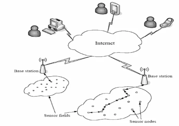
has one or more sensors and is deployed very close or inside a control environment (for example, to detect temperature change in a room). It monitors events and processes and communicates the information gathered to other nodes in the network. Each node may have multiple wireless links with other nodes and eventually to a base station that serves as a gateway for the network, bridging it with other networks similar to the Internet. Information moves node by node from the point of generation to the point of use. Typically, a node is composed of four elements: a sensing unit, a processing unit, a transceiver unit and a power unit. The sensing unit includes sensors and the analog-to digital converter that transforms the analog signal to a digital stream. The processing unit is made up of a microprocessor and a small memory and manages the tasks of collaboration with other nodes as well as carries out the sensing tasks. The transceiver unit is typically a radio that connects a node to its neighbors via radio frequency. The power unit is either a small battery, or some other form of power unit like a solar cell. The WSN leverages its resources based on the sum of all the nodes in the network. The deployment of nodes is usually dense, and has a high degree of interaction between them. The network can self-organize and self-heal when variations in connectivity occur, or when individual nodes fail. It is expected that many future monitoring systems will comprise wireless sensor networks and will be designed around the capabilities of some form of autonomous nodes. Figure 11 depicts the example of a WSN network [26]. It is to be noted that freedom from wires allows greater flexibility in sensor placement in construction, especially in a dynamic environment like the sites that employ mobile cranes. Construction managers will benefit from utilizing a variety of sensors and wireless communication technologies in their construction environments. The sensors get relevant information about what is being constructed, processes and equipment that are being used in constructing these, flow in supply-chains of materials that are
delivered to construction sites, and monitoring current conditions of an infrastructure and/or a building throughout the entire lifecycle. In the built environment, every structure has typical modes of vibration, acoustic emissions, and response to stimuli; variations in these behaviors indicate wear, fatigue or other changes. During the life of these
structures, if full history information were available at critical points, the mode and source of failure could be pinpointed and used as lessons for newer designs. By using sensors, the result of construction (ie: buildings, infrastructure, etc.) and the processes associated with managing the construction become smart. The net result is that
managers enhance their awareness, which will help them to make more informed decisions.
To put things in a business perspective in the wired world, the cost of running wires is usually high, perhaps in the order of thousands of dollars per foot. The cost of
incremental measurements for fewer dollars is a big motivator in the wireless world [23, 24]. Bigger savings are available with new applications that could not have been
achieved in a wired world, like office building and equipment performance management and condition monitoring for the purpose of maintenance. The underlying principle here is model-based predictive maintenance. Based on the collection of sensor data
(example temperature and vibration measurements), a satisfactory profile can be established. When it degrades, maintenance can be scheduled for a time that will be convenient to the client. In addition, in a wired world, as the wires age they can crack or
fail. Inspecting, testing, troubleshooting, repairing, and replacing wires require time, labor, and materials.
Figure 11: Wireless Sensor Network (Source: Yaqoob et al)
NIST [25] is currently exploring novel technologies for sensing in buildings using WSN. This will enable a building operator to place sensors without disrupting existing
construction and also allows sensors to be placed in spaces that may see changing configurations. There are several challenges to be addressed that include the ability to integrate data from these networks seamlessly into software applications, measures of reliability and robustness of the sensor networks in buildings, and estimates of lifetimes of sensor nodes. Major goals associated with this project are:
• To enable sensor technologies that will lead to energy savings and occupant comfort
• To enhance the amount of available data to building control & fault detection systems.
• To provide new forensic tools for finding and diagnosing problems in buildings.
• To promote the interoperability of data from various sources to improve the security of building occupants.
While the wireless technology brings such benefits as lower installation and
maintenance costs, faster up time, system flexibility, and scalability, it also presents several challenges to the user. In a wired environment, in certain cases, the same cable
is used for communication purposes as well as to supply with energy. If the cabling were to be dropped completely, alternative ways to supply stations with energy need to be found. In battery-driven stations, energy is a scarce resource and need to be used economically. Replacing batteries may not be practical and can lead to downtimes. In addition, choosing the ‘correct’ standards also plays a big role. The application
requirements for distance, bandwidth and power consumption dictate that different standards will be required, but finding what is right for a particular environment can be tricky.
5.5 Mobile Support
Mobile technologies have far reaching applications in construction automation. As suggested by Bowden et al [31], example uses of mobile technologiesinclude: a) the construction personnel can use advanced visualization and mobile devices (eg: phones and personal digital assistants) to zoom into different areas of buildings and check how to assemble various components; b) material delivery and tracking tags (eg: RFID) can be used as a prominent means for tracking material movement; c) progress monitoring and programming - as construction progresses, personnel can update the programming information, and problems or changes can be recorded on the fly, which will allow progress monitoring; d) as-built information - if the design is changed due to last minute considerations, which is often the case, as-built information can be captured and
handed over to appropriate personnel; e) real-time accident and near miss reporting, which will enable a proactive approach to health and safety on-site; f) reduction in down-time from unexpected problems via instant and meaningful communication with offsite personnel; g) proactive maintenance scheduling and remote delivery of
schedules and work orders.
6 . Re a l-t im e Proje c t M a na ge m e nt a nd Cont rol
The 3 major modules (refer FIATECH diagram in section 2.1) revolving around the construction process have been described already. Next we focus on a module that glue them together namely, the real time project management and control, which enables the three modules to function in a seamless manner. The FIATECH goal here is to identify and pursue data models, business processes and functions required to advance the development of a fully integrated facility planning and management system that may be seen as the real-time system across the design, construction and facility life cycle. In this context, an enabling technology, which has been the norm in
manufacturing sector, for business process automation is the enterprise resources planning (ERP) systems. But, most ERP systems target at the large international corporations with multi-product, multi-production facilities and customers across the globe. This notion has resulted in the development of large scale and expensive ERP systems. Whereas, if an ERP system is developed focusing mainly on the needs of construction firms, it can effectively limit the size of this system. And, the development and implementation costs will be significantly lower; whereby a typical construction contractor will be able to afford it. Bear in mind that more than 90% of construction firms are smaller in size, having less than 10 employees. Another important point is that, the
present day ERP systems emphasize standardization and automation, as they are tailored for large scale standard and repetitive operations and management processes that are typical in the manufacturing sector.
If one examines closely, some of the management functions required in a
manufacturing sector like product ordering, warehousing, and distribution are not that important in the construction domain. Whereas, managing a construction business requires certain functions that are not critical to manufacturers, like project cost estimating, project progress monitoring and control. To address the project-oriented nature of the construction business, project management functions needs to be enabled in a construction ERP system. Functions like estimating, planning, scheduling, resource allocation and optimization, and progress reporting monitoring/control are inherent in project management, and efforts will be needed to integrate these into a construction ERP whereby both project and business functions will be available as part of a single environment. In addition, to achieve the full benefits of process automation, the ERP system tailored to the needs of construction sector needs to be further enriched with workflow technologies that can invoke standard business process models. It needs to be noted that a workflow management system manages the flow of a process among participants according to the process definition consisting of a sequence of tasks. It can define, execute, coordinate, and maintain business processes typically via distributed applications.
6.1 Required Features of a Construction ERP
According to Shi and Halpin [8], a construction oriented ERP system needs to be:
Project-oriented: The construction business is operated around projects. Hence, in order for the construction sector to embrace an ERP system, it has to have the capability to manage ongoing projects with the ability to report progress status, cost status, profitability, and potential problems such as falling behind schedule, so that actions can be taken before they occur. Periodically, it would be necessary to
summarize and report to the corporate office to assess the current situation with respect to financing requirements, cash flow, purchasing, equipment, and human resources. If there is a conflict, such as two projects competing for the same resources, corporate level decisions may be taken to maximize the overall interest of the enterprise. Such requirements are not very critical in a manufacturing oriented ERP system.
Integrated: Within a construction company, there are many business functions like estimating, project management, accounting, finance, engineering, contracting,
procurement and equipment. Understandably, the office staff would interact with each other to make decisions, to continue ongoing projects, and to bid on new projects; obviously, these offices would be connected as an integrated system. Also, every office would get needed information online to support its management functions; update its responsible databases and make decisions that would be made available online for other offices – such as updates on material deliveries allowing site managers to plan site operations; and any new projects entered by the bidding section that would allow the operations division to schedule and plan its construction. In short, all ERP systems must be integrated with the various business functions. But, from a construction view
point, a contractor’s business functions are not typically transparent to its manufacturing counterpart.
Parallel, distributed and expandable: As is typical, several functions are concurrently carried out by the managers of the various offices. Hence, it is useful for an integrated ERP system to use parallel and distributed technology to support the multiple
concurrent applications or requests. For example, an estimator may be searching the cost database to determine the bid price of a new project; in parallel, a cost engineer may be updating the database with recent project data. Likewise, several applications like estimating software and scheduling software may be running. The ERP system should interact with an application through a series of approaches: 1) as a direct request from a user to start the scheduler to schedule a project; 2) call upon an
application to get percentage completion of the project to prepare a progress payment request, and 3) facilitate two-way data exchanges between an application and the ERP system after a new project is added, and the project data is stored in the central
database for users to access. Accordingly, an open and expandable architecture allows a company to tailor its needed applications to fit its business needs with minimum effort for customization. These requirements are more important in a construction ERP than for a manufacturing oriented ERP system.
Scalable: Having an ERP system implies major capital has been invested, and it should support the strategic development of the company for many years to come. Scalability to accommodate any expanded management functions should be taken into account as part of the business case for acquiring an ERP system. A contractor may start
implementing an ERP system with only accounting and project management functions, so that only staff in these two offices needs to access the system initially. Later, other functional modules may be added to the system. A scalable system is preferable in a construction enterprise in order to meet expandable requirements.
Remotely accessible and reliable: Construction projects are executed on remote sites, often miles away from the head office. Remote accessibility enables project managers and other site personnel to access central information (like purchasing and financing data), while the head office can obtain the updated project progress information for the senior management to assess the progress and project performance. Reliability is a common feature required for all decision-supporting systems. The right data must be retrieved from the cost database to support estimating; for example, a purchase order must be reviewed and be approved in the right sequence; a request to reserve a piece of equipment must be processed and a reservation made, or if the request cannot be satisfied, the requester must be notified.
6.2 Workflow Enriched Construction ERP
Workflow technology is a key technology for enabling business process automation in ERP systems. Some ERP systems have already incorporated workflow management systems to complement their data centric feature, to separate the flow logic in ERP system from its function logic, and to bring in the process centric feature of workflow management systems. But generally, the present day ERP systems allow only limited
flexibility for users to customize embedded standard business process models that are often derived from best practices.
The purpose of a workflow management system is to take care of the information
logistics as well as to facilitate a process overview that enables better management and control of the process [14]. Such systems have proven to be very successful in
supporting well-defined and structured processes. It is becoming an important driver in improving and integrating processes in the service industry. Even though each project is unique in nature, construction processes on a detailed level are very similar. Typically, the process of construction is repeated from project to project. By making graphical process definitions with models describing the life cycle of a typical ‘workflow instance’ in isolation, one can configure these systems to support business processes.
Workflow technologies can enable the modeling and automating of construction
business processes. Taking advantage of the Internet, construction management tasks can be organized as distributed internet applications for supporting the reusability of software components, simplifying process modeling, and automating business processes. One can incorporate several modules like an object-oriented reusable component technology for modeling construction management tasks; a construction business process modeler based on the task based modeling methodology; a request driving methodology for raising business requests and instantiating corresponding process instances; and, supporting technology for interacting with a commercial workflow engine for executing business process instances.
Workflow management systems support different types of workflows such as process discovery, case handling, collaboration, and component workflows. Each system may be developed as a central client/server architecture involving a combination of human and computer-based tasks involving several technologies. A component-based
workflow system development practice is a good approach to increase the reusability of the software components. To enable reusability, a task must be developed as an
independent software component with the characteristics of independency,
encapsulation, completeness, and consistency. A component-based approach will help to eliminate major problems that have slowed down the adoption of ERP technologies in many industries.
The workflow methodology may be conceptualized as a network. Within a business process, the entity representing knowledge that is relevant to a specific task (note: a task may have sub-tasks), may be termed a ‘knowledge object’. And it facilitates
breaking down a complex business process into a number of sub-processes. A network of knowledge objects, with associated knowledge sources and relationships, can be created as a ‘knowledge map’. A knowledge map provides building blocks describing the contents of tasks and, can be further evaluated to filter out any irrelevant
knowledge. A network of knowledge objects, required for the completion of a business process, dictates the order of task execution, and also creates a horizontal (input-output) relationship. The horizontal relationship enables the requirements for process (or workflow) management. During the execution of a business process, only required knowledge (relevant to the specific task in charge) will be collected from the data
repository for the user. Here, knowledge may be filtered based on a user profile relevant to a particular task. That is, only the knowledge appropriate to a particular task and its linked associates (relevant to the user) need to be presented at any given time.
Typically, it works in the following manner: • A project manager (user) logs on
• The system verifies the user id, profile, etc.
• If a valid user, it is sent out of the Workflow Management (WM) system
• The WM fetches tasks relevant to the user (from a database) and displays them on the user interface
• The user selects a specific task to execute
• The WM collects details of the task and knowledge associated with linked items • The WM displays a knowledge map based on the above
• The user chooses a particular knowledge object
• The knowledge object details are collected from the repository for the user to use.
6.3 An Intelligent System for Process Automation
Lee and Shi [9] have described an intelligent system for construction process
automation under the heading ‘Construction Business Automation System’. It uses a three-tier client/server architecture, which separates the system’s functions into three distinct abstractions as shown in Fig. 2. The system has 5 functional modules
comprised of: 1) the construction business process modeler (CBPM); 2) the request navigator (RN); 3) the workflow management system; 4) the workflow system database; and 5) legacy databases. Of these, CBPM and RN are external modules, which are mapped onto the system through a workflow application programming interface (WAPI). Referring to Figure 12, the intelligent management server, which follows standard
workflow architecture, provides the workflow application programming interface that also exposes its objects to external applications and client tools in a distributed environment. The CBPM ( ) is a business process-modeling tool for creating process models. It allows process modelers to define process models by assembling the task components to be selected from the task library ( ). The request navigator ( ) is a client side
application that enables a user to select a corresponding request form, to find a process model in the process model repository, and to instantiate an instance of the process. The WfMS is the intelligent management server (located on the second tier) that invokes run-time task components (like sending email, searching a database) as
modularized applications at the server side ( ) by using WAPI ( ). It retrieves or stores the data of process models or instances from the workflow system database. The workflow engine ( ), part of the WfMS, is the simulation engine for starting, executing, tracking, and terminating a process instance. It tracks who performs a particular task, delivers a task component to a responsible person, stores the returned data in the database, schedules the next task component, and keeps a record of all of the operations in an audit database. CBPM ( ) behaves as a client side application that communicates with the intelligent management server at the 1st tier, at the ‘process model design time’ (left-hand side of Fig. 2). After a business process model is created by using the task components in the Task Library ( ), CBPM connects to the workflow engine ( ) and creates a process model in the process model repository ( ) via WAPI
( ). At the process instance run time (right-hand side of Fig. 2), the request navigator ( ) is the client side application for executing the request-driving methodology. It captures the user’s browsing behavior and searches for a corresponding request form. After the form is completed, the request navigator connects to the workflow engine ( ) to query for a corresponding process model in the process model repository ( ). If a model exists, the workflow engine instantiates a process instance into the process instance repository, executes the process instance, and executes task components in the workflow DNA repository ( ) according to the sequence defined in the model. A Microsoft 2000 SQL Server is used for the workflow system database ( ) in this prototype.
6.4 ERP Commercial Tools
Enterprise resource planning (ERP) systems have become more and more prevalent throughout the business world. These systems are meant to integrate and partially automate many of an enterprise’s business processes. Generally speaking, commercial ERP packages cannot provide a once-and-for-all business model for all processes in all industries. Thus, no single ERP packaged software can meet all the functionalities or all special business requirements. Organizations need to look into choosing a flexible ERP system and a co-operative vendor that effectively responds to customer requirements. Companies like SAP and Oracle offer widely known ERP systems and have collectively sold billions of dollars worth of such systems to numerous industries, which also
includes the construction sector. Another system, OPTICON [10] is claimed to be comprehensive, integrated, and a modularized ERP System for the construction industry. This particular system can run both at the site as well as at head office independently, and the head office can be linked with the site office through web server/data transfer protocols, thus the status of each site is known.
Some system modules, provided by certain other software vendors, have been found to be ill-suited to the construction sector; a few companies that introduced ERP failed the functionalities altogether. These failures occurred mainly because the level of IT
application in these construction companies was comparatively low. Thus, considerable attention needs to be paid in advocating ERP systems [12]. Though many commercial ERP implementations are reported, requirements for enhancements such as project management functions, workflow management and data exchange requirements between owners and contractors are identified as major modules for value enhancing additions [11].
6.5 Construction Integrated Management System
In line with construction enterprise resource planning (CERP) systems, there were other attempts to boost the automation of the construction process. For example, Shiau et al [13] advocated a Construction Integrated Management System (CIMS). It utilizes an object-oriented concept, E/R techniques and the Delphi environment to develop a Construction Integrated Manage System (CIMS). With the help of CIMS, one can effectively control various details such as bidding, purchasing, contracting and
evaluating which are associated with each stage in construction. The integrated system can practically control all information, and consists of several modules like, the Basic Database, Budget Module, Procurement Module, and Price Calculation Module. The data stored in this system includes the resource data, work data, material analysis data, project instance data, subcontractor’s data, labor data, project data, owner’s data and database maintenance data. Its Budget Module is used to calculate the
construction cost based on drawings, rules and other documentations. The system uses individual works associated with the project as a basis to estimate the quantities of labor, machinery and material required for each unit, which is used as a basis for
procurement and price calculation operations. The Procurement Module provided by the system is used by construction management to control dynamic market prices, conduct price negotiation, and evaluate profit scenarios. The Price Calculation Module is used to transfer the data about the works and quantities from the site daily report system, and
perform the price calculation for the current works at the site. The system reads the data for contract quantity, procurement counts and cumulative payment request counts for cross comparison and analysis. If it finds that the payment request counts exceed the procurement counts, then an alert is triggered. Management can control the expected and actual construction status in the system and prevent the occurrence of problems as early as possible thereby minimizing the risk.
6.6 Integrated Project Systems & Computer Assisted Construction Planning
Mahmoud Halfawy and Thomas Froese [36, 37] have proposed a model-based
approach that employs “smart objects” to implement integrated project systems. Smart AEC objects are semantically-rich, product-centric data models that include an AEC object or object assemblies that not only represent the data attributes of these objects, but also encapsulate the objects’ behavior and intelligence in the form of behavioral attributes, object inter-relationships, design rules, and configuration constraints. These objects are software components that implement the structural, functional, and
behavioral characteristics of domain objects and support the representation of various aspects of project information relevant to these objects. Besides serving as data models that integrate multi-perspective project views and encapsulate behavioral object
intelligence, smart objects also enable the exchange of semantically-rich data models between different software tools.
Smart objects offer many benefits in the design process including 1) modeling
behavioral aspects within individual objects, as well as between interdependent objects, and integrating those aspects with the structural and configuration aspects of AEC objects; 2) automating routine decisions and design checks that could be based on geometric or non-geometric objects parameters; 3) automating propagation of changes and enforcing design constraints and rules to maintain design consistency and validity; 4) integrating the design with other project activities (eg: scheduling, estimating) and thus facilitating information sharing across project activities; 5) reducing the time needed to design complex objects and allow designers time to focus on design issues and to perform quicker design iterations; 6) providing feedback to designers if any constraints or requirements are violated; and 7) capturing and encapsulating the design rationale into these objects.
Jeff Rankin and Thomas Froese [38] have detailed the requirements of integrated construction management systems and the need to support the management of large volumes of information on several levels. Their solution entails a combination of a user interface, and methods to partially automate the creation of the required information through access to stored information from past projects. Their work follows the path being established for integrated construction management systems that rely on a standard representation of the industry’s information requirements. By exploring the comprehensive aspects of construction planning for an integrated construction management system, this work demonstrates the usefulness of applying sound
information representation structures. Through the application of case-based reasoning, this research advances the concepts of planning tools as they apply to integrated