Publisher’s version / Version de l'éditeur:
Vous avez des questions? Nous pouvons vous aider. Pour communiquer directement avec un auteur, consultez la
première page de la revue dans laquelle son article a été publié afin de trouver ses coordonnées. Si vous n’arrivez
Questions? Contact the NRC Publications Archive team at
PublicationsArchive-ArchivesPublications@nrc-cnrc.gc.ca. If you wish to email the authors directly, please see the first page of the publication for their contact information.
https://publications-cnrc.canada.ca/fra/droits
L’accès à ce site Web et l’utilisation de son contenu sont assujettis aux conditions présentées dans le site LISEZ CES CONDITIONS ATTENTIVEMENT AVANT D’UTILISER CE SITE WEB.
The 12th Canadian Conference on Building Science and Technology [Proceedings], pp. 567-578, 2009-05-06
READ THESE TERMS AND CONDITIONS CAREFULLY BEFORE USING THIS WEBSITE.
https://nrc-publications.canada.ca/eng/copyright
NRC Publications Archive Record / Notice des Archives des publications du CNRC :
https://nrc-publications.canada.ca/eng/view/object/?id=de1ba6e7-b02a-4ff0-97f2-fb7dbb595b8e https://publications-cnrc.canada.ca/fra/voir/objet/?id=de1ba6e7-b02a-4ff0-97f2-fb7dbb595b8e
Archives des publications du CNRC
This publication could be one of several versions: author’s original, accepted manuscript or the publisher’s version. / La version de cette publication peut être l’une des suivantes : la version prépublication de l’auteur, la version acceptée du manuscrit ou la version de l’éditeur.
Access and use of this website and the material on it are subject to the Terms and Conditions set forth at Air leakage vs. air intrusion in low-sloped roofing assemblies
Air le a k a ge vs. a ir int rusion in low -slope d
roofing a sse m blie s
N R C C - 5 0 8 2 0
M o l l e t i , S . ; B a s k a r a n , B . A . ; K o , K . P . ; B e a u l i e u , P .
M a y 2 0 0 9
A version of this document is published in / Une version de ce document se trouve dans:
12th Canadian Conference on Building Science and Technology, Montréal, Quebec, May 6-8, 2009, pp. 567-578
The material in this document is covered by the provisions of the Copyright Act, by Canadian laws, policies, regulations and international agreements. Such provisions serve to identify the information source and, in specific instances, to prohibit reproduction of materials without written permission. For more information visit http://laws.justice.gc.ca/en/showtdm/cs/C-42
Les renseignements dans ce document sont protégés par la Loi sur le droit d'auteur, par les lois, les politiques et les règlements du Canada et des accords internationaux. Ces dispositions permettent d'identifier la source de l'information et, dans certains cas, d'interdire la copie de documents sans permission écrite. Pour obtenir de plus amples renseignements : http://lois.justice.gc.ca/fr/showtdm/cs/C-42
AIR LEAKGAE vs. AIR INTRUSION IN LOW-SLOPED ROOFING
ASSEMBLIES
Suda Molleti, 1*,Bas A. Baskaran 2, Steven Ko3, Pascal Beaulieu3
1
Research Officer, 2Senior Research Officer, 3Technical Officer National Research Council of Canada
1200 Montreal Road, Ottawa, ON, Canada, K1A OR6
*Corresponding Author. Tel: 613-993-9673;Fax:613-998-6802;sudhakar.molleti@nrc.ca
ABSTRACT
In conventional low-slopped roof assemblies, where the waterproofing membrane is attached through insulation and other components to the structural deck at discrete points using fasteners, it is known as a mechanically attached assembly (MAA). In North America, approximately one fourth of low-slope buildings are roofed with a mechanically attached assembly having a single-ply membrane. In these roofing assemblies most of the attention has been focused on the performance of individual roof components to maintain the integrity of the waterproofing system. Relatively little attention has been given to the overall assembly performance with regards to air movement. A common misconception is that air movement in roofing assemblies can be characterized by air leakage similar to that which occurs in walls and windows. However, the material properties and assembly response indicate that there is no air leakage in the mechanically attached low-sloped membrane roofs. However, air intrusion does occur in these assemblies. Air intrusion is a phenomenon in mechanically attached roofing assemblies, which occurs due to the membrane response to the external wind pressures. Incorporating an air retarder at the deck level can minimize this air intrusion. National Research Council of Canada (NRC) has been conducting research on the wind uplift performance of mechanically attached roofing assemblies for the past one decade. Wind uplift data is available for different roofing configurations, which can be generalized into two categories: 1) assemblies without air retarder and 2) assemblies with air retarder. From these categories, a typical mechanically attached assembly is evaluated for wind uplift performance. By analyzing the measured membrane and insulation responses of these assemblies, this paper attempts to clarify the air movement confusion of air leakage vs. air intrusion in mechanically attached low-sloped membrane roofs.
1. INTRODUCTION
In North America, low-sloped roofing assemblies fall into two broad categories according to the location of the waterproofing membrane (Baskaran et al., 1997): the protected roofing assembly in which the membrane is below the insulation and the conventional roofing assembly in which the membrane is on the top where it is exposed to external conditions, such as wind, snow, rain, ultraviolet radiation and temperature changes. This study focuses on the behavior of conventional roofing assemblies. In conventional roof assemblies, the membrane can be mechanically attached, fully adhered or partially attached to the substrate. A roofing assembly in which the membrane is attached, through insulation and other components, to the structural deck at discrete points using fasteners is known as a mechanically attached assembly (MAA). The membrane can be single ply, such as PVC
(polyvinyl chloride), EPDM (ethylene propylene diene monomer), TPO (thermoplastic olefin), or modified bituminous (mod-bit). About one fourth of North American low-sloped buildings are roofed with mechanically attached assemblies (NRCA, 2004) and its popularity continues to grow.
In these roofing assemblies most of the attention has been focused on the performance of individual roof components to maintain the integrity of the waterproofing system. Relatively, very little attention has been given to the overall assembly performance with regards to air movement. With the growing energy concern and increasing roof failures, air movement in roofing has gained importance. However, the air movement pattern is still misunderstood within the building community. A common misconception is, air movement in roofing assemblies can be characterized by the air leakage that typically occurs in walls and windows. Some of the factors that contribute to this confusion are the existing energy and building code requirements and the current air barrier standards, which are all focused on wall assemblies. Kalinger (2008) clearly documented that “ASTM E2357-05 - Standard Test Method for Determining Air Leakage of Air Barrier Assemblies” contains three references to roofs in contrast to forty five references to walls. He also states that “roofs are not simply horizontal walls, and it is inappropriate to generalize information and requirements relating to wall performance to low-slope roof assemblies”.
For airflow to occur across a building component, there must exist two prerequisites, one is the pressure difference between two locations, and the other is a continuous flow path or openings connecting the locations. In the building envelope, air movement can be described by the following terms (Molleti et .al 2008):
Air leakage: When air enters or leaves from one environmental condition to the other environmental condition through the building envelope assembly such as walls and windows, it is termed as “Air Leakage”.
Air Intrusion: When the conditioned indoor air enters into a building envelope assembly, such as roofs, but cannot leave the assembly to exterior environment, it is termed as “Air Intrusion”.
Figure 1 differentiates the concept of air leakage and air intrusion through a typical example of brick cladding wall with the mechanically attached membrane roof assembly. As shown in the Figure 1, the definition of air leakage is very much valid for walls and windows where their system characteristics allow for air movement from indoor to outdoor and vice versa. This is not the case for the roofing assemblies. In membrane roofs the waterproofing membrane is impermeable (Bomberg and Kumaran 1985, CMHC 1988). If constructed properly, it can certainly perform as an air barrier impeding any air movement from exterior environment to the interior and vice versa. The membrane being the primary air barrier can prevent air leakage roofing assemblies (Kalinger,2008).
From an assembly perspective, such as in mechanically attached roofing systems or the ballasted single-ply roofing systems, due to the flexible and elastic nature of the membrane, the action of wind and mechanical pressurization can cause the membrane to balloon or flutter. The magnitude of the wind induced suction; the membrane’s elastic properties and the fastening density determine the magnitude of the membrane billowing. The deflection
(billowing) of the membrane leads to a volume change (expansion) of the roof space between the membrane and the deck creating negative or bubble pressure in that space. To equalize the negative pressure, the indoor conditioned air is drawn into the assembly as shown in Figure 1. Flow paths within the assembly are present due to the air permeability of the subsurface components under the membrane and joints/junctions/penetrations in the roofing assembly. Figure 2 gives an example of some of flows paths in the roofing assemblies.
Figure 1: Concept of air leakage (brick cladding wall) vs. air intrusion (mechanically attached roofing system)
Deck flutes
Deck seams
Fastener penetration
Figure 2: Example of flow paths within the roof assembly: deck seams, flutes and fastener penetrations
In any building envelope assembly, the principal function of the air barrier is to prevent air from leaving or entering through the assembly (air barriers may be single components or a
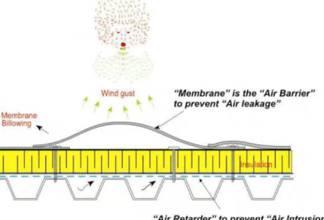
system). In roofs, the waterproofing membrane, as shown in Figure 4, successfully fulfills the function of an air barrier. However, to prevent air intrusion or air from entering into the roof assembly in MAA flexible membrane systems, another component is required at deck level. As shown in Figure 3, this component can be called as “air retarder”. This air retarder can be of any type, for example, a vapour barrier that can perform the dual role of controlling air and moisture can be used as air retarder. However, its design principles and construction practices should be compatible to ensure proper interconnection of materials within the assembly to mitigate both processes.
Figure 3: Role of air barrier and air retarder in roofing assemblies
National Research Council of Canada (NRC) has been conducting research on the wind uplift performance of mechanically attached roofing assemblies for the past one decade. Wind uplift data is available with different roofing configurations. This data can be generalized into two categories 1) assemblies without air retarder and 2) assemblies with air retarder. From these categories, a typical mechanically attached assembly were evaluated for wind uplift performance. By analyzing the measured membrane and insulation responses of these assemblies, the paper attempts to clarify the air movement confusion of air leakage vs. air intrusion in mechanically attached low-sloped membrane roofs.
2. EXPERIMENTAL INVESTIAGTION
Experimental work was carried out at the Dynamic Roofing Facility (DRF) established at the IRC/NRC. Baskaran and Lei (1997) provide a detailed documentation of the facility’s features. The DRF consists of a bottom frame of adjustable height upon which roof specimens are installed and a movable top chamber. The bottom frame and top chamber are 240 in. (6100 mm) long, 86 in.(2200 mm) wide and 32 in. (800 mm) in height. The top chamber is equipped with six windows for viewing, and with a gust simulator, which consist of a flap valve connected to a stepping motor through a timing belt arrangement. All the tested specimens were subjected to the CSA A123.21 dynamic test protocol. CSA A 123.21 represents the only North American test procedure for assessing the wind load uplift resistance of roofing systems under dynamic wind load conditions. Through rationalized dynamic load cycles that were developed through wind tunnel testing of full-scale roof assemblies, CSA A 123.21 induces dynamic pressures that can be said as the true
representation of wind action. It has five rating levels (A to E). Each level consists of eight load sequences, with different pressure ranges. The eight load sequences are divided in two groups. Group 1 represents wind-induced suction over a roof assembly. It consists of four sequences, where the pressure level alternates between zero and a fixed pressure. Group 2 represents the effects of exterior wind fluctuations combined with a constant interior pressure on a building, which is one the key attribute of the CSA A 123.21.
Following the above experimental approach different roofing configurations have been constructed and tested. These roofing configurations can be generalized into two categories:
1. Assemblies without air retarder 2. Assemblies with air retarder
From each of these categories, a typical thermoplastic assembly were evaluated for the wind uplift performance. Both the assemblies have similar configuration and layout except the air retarder component. Figure 4 shows the installation of a typical mechanically attached assembly without air retarder. The tested systems consisted of the following common roofing components whose general physical and mechanical properties are:
Deck: 0.76 mm (22-Ga) thick corrugated steel deck with a profile height of
1.5 in. (38 mm) and a flute width of 5.9 in.( 150 mm). The steel deck was fastened using size-10 round-head screws at every flute with wooden beams of the DRF. The wooden beams are 6 in. x 6 in. (152 mm x 152 mm) in size and spaced about 72 in.( 1829 mm) apart. The black dotted lines as shown in Figure 4(a) represent the seam overlaps of the steel deck.
Insulation: 2 in.( 50 mm) thick polyisocyanurate (ISO) boards of 4 ft x 8 ft (1.2 m x 2.4 m) are mechanically attached to the steel deck using 8 fasteners per board. Fasteners were 5 in.( 127 mm) long with plastic plate 3 in. (76 mm) diameter. Figure 4(b) shows typical installation of insulation boards
Membrane: Reinforced poly vinyl chloride (PVC) thermopastic membrane was
used as the roofing membrane. The membrane had a thickness of 0.045 in.( 45-mil) and a width of 78 in. (1981 mm). The installation procedure is shown in Figure 6. For the tested assembly, membrane sheets were fastened at a 12 in. (305 mm) spacing (Fs) along the seam [Figure 4(c)]. The adjacent sheets were then overlapped and hot air welded along the seam to obtain continuity [Figure 4(d)]. The completed assembly is ready for testing as shown in Figure 4(e)
3. RESULTS AND DISCUSSION
As described above, when a mechanically attached roofing assembly is subjected to negative wind uplift test conditions, the membrane is lifted or ballooned between the attachment locations as shown in Figure 5. This deformed membrane response is a clear indication of the absence of air leakage in membrane roofing assemblies. This has been validated through experimental data as follows:
(c) (d) (e) (a) (b)
Figure 4: Typical installation of membrane roof assemblies without air retarder
At the construction stage, both the membrane and insulation were instrumented with sensors to measure their response. Figure 6 gives an example of the measured response data of an assembly without air retarder. From Figure 6 (a), which represents the membrane pressure, the data indicates that it sustained a maximum negative wind uplift pressure 77 psf (1.6 kPa) and passed all the sequences up to Level B before it failed in the sequence 4 of Level C. The respsone to these uplift pressures is the membrane deflection as shown in Figure 6(b). This membrane deflection creates negative pressures between the insulation and the underside of the membrane as shown in Figure 6(c).
Figure 6:Typical measured response data during wind uplift testing of assemblies without air retarder
To expand on this process, Figure 7 plots the experimental data of membrane pressure, insulation pressure, and membrane deflection for about five wind gusts at a pressure level of 45 and 77 psf (2.2 and 3.7 kPa) and each having duration of about 8 seconds. Within the 8-second period, when the membrane experiences the maximum pressure of 45 and 77 psf (2.2 and 3.7 kPa) for 2 seconds, it is subjected to a maximum deflection of 6.5 and 8 in. (165 and 200 mm). This deflection or ballooning of the membrane creates a negative or bubble pressure underneath the membrane across the insulation, which is about 60 to 70 % of membrane pressure.
Depending on the deflection of the membrane, the magnitude of bubble pressure can vary. The membrane deflection is a function of (1) the elasticity of the membrane type (2) membrane width (3) fastening pattern (4) fastening density and (5) air tightness of the sub surface components. Relating the membrane width to deflection, Figure 8 compares the membrane deflections for three different membrane types commonly used in the market. These data are taken from wind uplift database at a typical test pressure of 60 psf. The empirical data clearly shows that irrespective of the membrane type, membrane deflection increases with the increase in membrane width. With similar sheet widths, thermoset
membrane had higher deflection compared to the thermoplastic. This is indicative of the elastic nature of the thermoset membranes and also verifies the role of membrane elasticity in membrane deflection.
Figure 7: Typical membrane-insulation response during wind uplift testing of assemblies without air retarder
From the above data and discussion, the response of the mechanically attached roofing assemblies is evident. However, what still remains unanswered is, whether this response between the different roof components leads to air leakage in these assemblies. In other words, are these systems vulnerable to air leakage or air intrusion?
For the air leakage to occur, two conditions must be fulfilled: pressure difference across the assembly and flow paths in the assembly. In mechanically attached assembly: (1) the membrane’s response to the external pressure and resulting pressure difference across the insulation fulfills the first condition of pressure difference (refer Figure 6) (2) even though the joints and penetrations of subsurface roofing components of the assembly present flow paths, the waterproofing membrane, being impermeable, does not allow the entered air to exfiltrate to the outdoor environment (refer Figure 1). i.e the second condition for air leakage to occur is not fulfilled. If the membrane is permeable, or the assembly exhibits air
leakage, there should be no pressure difference across the membrane and the membrane should not deflect or respond to the wind uplift pressure when subjected to wind pressures. However, the data presented in Figures 6,7 and 8, showing higher membrane deflections reveals, that in membrane roofing systems, the membrane is the primary air barrier, and the fact that it responds and allows the assembly to sustains high wind uplift pressures is a validation that there is no air leakage in membrane roofing assemblies.
Figure 8: Effect of membrane type and width on the membrane deflection of assemblies without air retarder
In MAA flexible membrane roofing systems, the process is not as that of air leakage but one of air intrusion into the roof assembly. From Figure 7, the data shows that insulation pressure is almost 60 to 70% % of the membrane pressure. This insulation pressure is also called bubble pressure. To equalize the bubble pressure, the indoor conditioned air is drawn into the assembly as shown in Figure 1, which is defined as “air intrusion”. To minimize the air entering into the roof assembly, an air retarder as shown in Figure 9 is installed between the deck and insulation. Styrene butadiene styrene (SBS) modified surface reinforced vapor barrier was used as the air retarder. It has a thickness of 1/32 in (0.8 mm) thick. It is a self-adhering film and it comes in strips of 45 in (1140 mm) wide. According to the manufacture specification, these films can be directly applied over the steel deck as done in Figure 9.
When subjected to the wind uplift testing, the assembly with air retarder sustained a wind uplift pressure of 90 psf (4.3 kPa) [Figure 10(a)] before it failed to membrane tear around the fastener plate. The presence of air retarder reduced the air intrusion in to the assembly and provided suction resistance to the billowing membrane, which has translated into lower membrane deflection and lower negative pressures across the insulation as shown in Figure 10 (b) and 10 (c). At the sustained pressure of 90 psf (4.3 kPa), the membrane deflection was around 6 inches and the insulation pressure was almost 40 to 50 % of the membrane pressure. Ideally, with the presence of air retarder the membrane should not deflect as there will be no pressure difference across the membrane. However, it should be noted that in the present assembly, the air retarder has numerous insulation and membrane fastener penetrations, which might have created the necessary flow paths for the air intrusion, affecting the suction resistance and thereby allowing the membrane to deflect. Relating the membrane deflection to air intrusion, Figure 11 compares the membrane deflections of these two assemblies, with and without air retarder. The comparison clearly shows that due to the air intrusion resistance provided by the air retarder the membrane deflection is reduced almost by 40 % compared to the assembly without air retarder. The insulation pressures reveal that the component to be installed as an air retarder, apart from its air permeability characteristics, should demonstrate adequate structural strength to withstand these insulation pressures.
Due to this responsive characteristic, air movement in roofing systems is considered to be different from other building envelope components. Moisture migration and damage from condensation, dislodgement of membranes, wind scouring of gravel ballast and energy wastage are only some of the problems encountered with uncontrolled air intrusion. To comprehend these impacts, it is very important to quantify the nature of flow paths and the amount of air intrusion in these roofing assemblies, which has not been researched. This is possible by conducting thorough experimental studies, which are currently missing in the roofing literature.
4. Conclusion
Based on the presented results and discussions, the following conclusions can be drawn: Of the two conditions for air leakage mechanism, pressure difference and flow paths, mechanically attached membrane roof assemblies do not fulfill the condition of flow path through the assembly due to the impermeability nature of the waterproofing membrane i.e the condition of air leakage is not fulfilled.
Data from wind uplift testing indicates 30 to 40% of pressure distribution across the insulation and high membrane deflections. If the membrane is permeable or the assembly has air leakage, the test results should be opposite with no membrane deflection. These results prove that there is no air leakage in membrane roofing assemblies.
The response of the mechanically attached membrane roofs to the external pressures makes them vulnerable to “air intrusion”. The pressure difference across the insulation and the flow paths within the subsurface roofing components fulfills the two conditions for the air intrusion mechanism in these roofing assemblies.
Figure 10:Typical measured response data during wind uplift testing of assemblies with air retarder
Assembly without air retarder
Assembly with air retarder
Figure 11: Comparison of membrane deflection between assemblies with and without air retarder
Control of air intrusion will significantly reduce the forces acting on the membrane while minimizing their contributing impact to roof failures. Installing an air retarder above the deck can mitigate air intrusion. However, a thorough understanding of design principles and construction practices is required to ensure the compatibility of the air retarder materials with the roofing assembly components. Therefore research pertaining to air intrusion is crucial for the success of the roofing system performance.
REFERENCES
American Society of Testing and Mtaerials (ASTM) E2357 – 2005, Standard Test Method for Determining Air Leakage of Air Barrier Assemblies.
Baskaran, A.; Chen, Y.; Vilaipornsawai, U., "A New dynamic wind load cycle to evaluate flexible membrane roofs," Journal of Testing and Evaluation, 27, (4), July, pp. 249-265. 1999
Baskaran, A. and Lei, W., "A New Facility for Dynamic Wind Performance Evaluation of Roofing Systems". Proceedings of the Fourth International Symposium on Roofing Technology, NRCA/NIST, Washington, D.C., U.S.A., pp. 168-179, 1997.
Baskaran, A., Lei, W. and Richardson C., “Dynamic Evaluation of Thermoplastic Roofing Systems for Wind Performance,” Journal of Architectural Engineering, ASCE, vol. 5, No 5, pp. 16-24, 1999
Baskaran, B.A., Molleti, S., Sexton, M., "Wind uplift performance of roofing systems with vapour barrier," 9th Canadian Conference on Building Science and Technology
(Vancouver, B.C., February 27, 2003), pp. 349-364, February 01, 2003
Bomberg, M. and Kumaran,M.K., “A Test Method to Determine Air Flow Resistance of Exterior Membranes and Sheathing”. Building Research Note No. 227, National Research Council, Ottawa, April,1985.
CMHC (1988). Air permeance of building materials, Canada Mortgage and Housing Corporation, Ottawa, Canada.
CSA Number A123.21-04 (2004),”Standard test method for the dynamic wind uplift resistance of mechanically attached membrane-roofing systems”, Canadian Standards Association, Canada.
Kalinger, P., “ The Roof as an Air Barrier,” Proceedings of the RCI 23rd International Convention & Trade Show - February 28 - March 4, 2008, Phoenix, Arizona
Molleti, S., “Performance Evaluation of Mechanically Attached Roofing Systems.” Ph.D. thesis, University of Ottawa, Ottawa, Canada, 2006.
Molleti, S., Baskaran, B.A., Ko, S.K.P., "Development of a new test method for air
intrusion quantification of roofing assemblies," Journal of Testing and Evaluation, 36, (3), May, pp. 230-241, 2008.
NRCA.2004. Hurricane Charley: A Preliminary Report, Professional Roofing Magazine, National Roofing Contractors Association, October.