Publisher’s version / Version de l'éditeur:
Vous avez des questions? Nous pouvons vous aider. Pour communiquer directement avec un auteur, consultez la
première page de la revue dans laquelle son article a été publié afin de trouver ses coordonnées. Si vous n’arrivez
Questions? Contact the NRC Publications Archive team at
PublicationsArchive-ArchivesPublications@nrc-cnrc.gc.ca. If you wish to email the authors directly, please see the first page of the publication for their contact information.
https://publications-cnrc.canada.ca/fra/droits
L’accès à ce site Web et l’utilisation de son contenu sont assujettis aux conditions présentées dans le site LISEZ CES CONDITIONS ATTENTIVEMENT AVANT D’UTILISER CE SITE WEB.
Research Report (National Research Council of Canada. Construction); no.
RR-331, 2013-10
READ THESE TERMS AND CONDITIONS CAREFULLY BEFORE USING THIS WEBSITE. https://nrc-publications.canada.ca/eng/copyright
NRC Publications Archive Record / Notice des Archives des publications du CNRC : https://nrc-publications.canada.ca/eng/view/object/?id=1334f20f-8ad9-401d-a303-abda1cb943b4 https://publications-cnrc.canada.ca/fra/voir/objet/?id=1334f20f-8ad9-401d-a303-abda1cb943b4
Archives des publications du CNRC
For the publisher’s version, please access the DOI link below./ Pour consulter la version de l’éditeur, utilisez le lien DOI ci-dessous.
https://doi.org/10.4224/21268575
Access and use of this website and the material on it are subject to the Terms and Conditions set forth at
Guide to calculating airborne sound transmission in buildings: [first
edition, October 2013]
Quirt, David; Zeitler, Berndt; Schoenwald, Stefan; Sabourin, Ivan;
Nightingale, Trevor
This First Edition from October 2013 was superseded by the Second Edition in April 2016. You can access the Second Edition here: http://doi.org/10.4224/21277599
N A T I O N A L R E S E A R C H C O U N C I L C A N A D A
RR-331
Guide to Calculating Airborne
Sound Transmission in Buildings
David Quirt, Berndt Zeitler, Stefan Schoenwald,
Ivan Sabourin, Trevor Nightingale
This page is intentionally left blank to ensure two-page examples are presented side-by-side on the screen when zoomed out sufficiently.
Although it is not repeated at every step of this guide, it should be understood that some variation is to be expected in practice due to changing specific design details, or poor workmanship, or substitution of
ge e i e ui ale ts , o si pl e uildi g the o st u tio .
Despite this caveat, the authors believe that methods and results shown here do provide a good estimate of the apparent sound insulation for the types of constructions presented.
Guide to Calculating Airborne Sound
Transmission in Buildings
Applying ISO Measurement and Prediction Standards in a North American Context
Abstract: In recent years, the science and engineering for controlling sound transmission in buildings have shifted from a focus on individual assemblies such as walls or floors, to a focus on performance of the complete system. Standardized procedures for calculating the overall transmission, combined with standardized measurements to characterize sub-assemblies, provide much better prediction of sound transmission between adjacent indoor spaces. The International Standards Organization (ISO) has published a calculation method, ISO 15712-1 that uses laboratory test data for sub-assemblies such as walls and floors as inputs for a detailed procedure to calculate the expected sound transmission
between adjacent rooms in a building. This standard works very well for some types of construction, but to use it in a North American context one must overcome two obstacles – incompatibility with the ASTM standards used by our construction industry, and low accuracy of its predictions for lightweight wood or steel frame construction. To bypass limitations of ISO 15712-1, this Guide explains how to merge ASTM and ISO test data in the ISO calculation procedure, and provides recommendations for applying
extended measurement and calculation procedures for specific common types of construction. This Guide was developed in a project established by the National Research Council of Canada to support the transition of construction industry practice to using apparent sound transmission class (ASTC) for sound control objectives in the National Building Code of Canada (NBCC). However, the potential range of application goes beyond the minimum requirements of the NBCC – the Guide also facilitates design to provide enhanced sound insulation, and should be generally applicable to construction in both Canada and the USA.
Acknowledgement: The authors gratefully acknowledge that the development of this Guide was supported by a Special Interest Group of industry partners who co-funded the project, and participated in the planning and review process. The Steering Committee for the project included the following members:
Steering Committee Member Representing
Robert Wessel Gypsum Association
Gary Sturgeon Canadian Concrete Masonry Producers Association
John Rice Canadian Sheet Steel Building Institute
Peggy Lepper Canadian Wood Council
Richard J. McGrath Cement Association of Canada
Sal Ciarlo Owens Corning Canada LP
Berndt Zeitler Stefan Schoenwald Bradford Gover
National Research Council Canada –
Construction – Building Envelope and Materials – Acoustics
Frank Lohmann Morched Zeghal
National Research Council Canada – Construction - Building Regulations – Canadian Codes Centre
The Advisory Committee that reviewed the draft Guide included the following additional members:
Advisory Committee Member Representing
Bob Mercer Canadian Gypsum Company Inc.
Dave Nicholson Maxxon Corporation
J. David Quirt Consultant
Contents
1. Sound Transmission via Many Paths ...6
1.1. Predicting Sound Transmission for Common Types of Construction ... 8
1.2. Standard Scenario for Examples in this Guide ... 9
1.3. Applying the Concepts of ISO Standards in an ASTM Environment ... 11
1.4. Combining Sound Transmitted via Many Paths ... 13
2. Buildings with Concrete or Masonry Walls and Concrete Floors ... 16
2.1. Concrete and Masonry Buildings with Rigid Junctions ... 19
2.2. Non-Rigid Junctions in Concrete and Masonry Buildings ... 29
2.3. Addi g Li i gs to Walls, Floo s, Ceili gs i Co ete/Maso Buildi gs ... 35
2.4. Simplified Calculation Method for Concrete/Masonry Buildings ... 51
3. Buildings with CLT Wall and Floor Assemblies ... 63
4. Buildings with Lightweight Framed Wall and Floor Assemblies ... 77
4.1. Wood-Framed Wall and Floor Assemblies ... 79
4.2. Lightweight Steel-Framed Wall and Floor Assemblies ... 93
5. Buildings with Hybrid Construction: ... 94
5.1. Concrete Floors with Lightweight Steel-Framed Partition Walls and either Heavy or Lightweight Façade. ... 94
5.2. Masonry or Concrete Walls with Joist Floors whose Concrete Deck has Rigid Floor/Wall Junctions ... 111
5.3. Concrete Masonry Walls with Lightweight Framed Floors and Walls ... 117
6. Other Construction Systems ... 129
7. Reference Material ... 130
7.1. Technical Reference Documents... 130
1. Sound Transmission via Many Paths
The simplest approach to sound transmission between adjacent rooms in buildings considers only the sound transmission through the wall or floor separating adjacent spaces. This perspective has been entrenched in North American building codes, which for many decades have considered only the ratings for the individual separating assembly: Sound Transmission Class (STC) or Field Sound Transmission Class (FSTC) for airborne sources or Impact Insulation Class (IIC) for footstep noise.
Implicit in this approach is the simplistic assumption (illustrated in Figure 1.1) that sound is transmitted
only through the obvious separating assembly—the separating wall assembly when the rooms are
side-by-side, or the floor/ceiling assembly when rooms are one-above-the-other. If the sound insulation is inadequate, this is ascribed to errors in either design of the separating assembly or the workmanship of those who built it, and remediation focusses on that assembly. Unfortunately, this paradigm is still common among designers and builders in North America. In reality, the technical issue is more complex, as illustrated in Figure 1.2.
Figure 1.1: The drawings in Figure 1.1 and 1.2 show a cross-section through a building with two adjacent rooms. Part of the sound from an airborne source in one unit (represented by red loudspeaker in the drawings, which could include anything from a home theatre to people talking loudly) is transmitted to the adjacent unit. The historic approach, illustrated in Figure 1.1, considers only the direct sound
transmission through the separating assembly.
Figure 1.2: In reality, there are many paths for sound transmission between adjacent rooms, including both direct transmission through the separating assembly and indirect structure-borne paths, a few of which are indicated here. (See Section 1.4 for more detail.) The structure-borne paths usually significantly affect the overall sound transmission.
There is direct transmission of sound through the separating assembly. But that is only part of the story. The airborne sound source excites all the surfaces in the source space, and all of these surfaces vibrate in response. Some of this vibrational energy is transmitted as structure-borne sound across the surfaces abutting the separating assembly, through the junctions where these surfaces join the separating assembly, and into surfaces of the adjoining space, where part is radiated as sound. This is called flanking transmission.
It follows that the sound insulation between adjacent rooms is always worse than the sound insulation provided by the obvious separating assembly. Occupants of the adjacent room actually hear the combination of sound due to direct transmission through the separating assembly and any leaks, plus sound due to structure-borne flanking transmission involving all the other elements coupled to the separating assembly. Transmission through wall Airborne Sound Source Separating assembly Transmission through wall Airborne Sound Source Separating assembly Flanking Transmission via ceiling surfaces Transmission through wall Airborne Sound Source Flanking Transmission via floor surfaces Flanking Transmission
via ceiling surfaces Transmission through wall Airborne Sound Source Flanking Transmission via floor surfaces
Of course, this has long been recognized in principle (and the fundamental science was largely explained decades ago, by Cremer et al [12]). The challenge has been to reduce the complicated calculation process to manageable engineering that yields trustworthy quantitative estimates, and to standardize that process to facilitate its inclusion in a regulatory framework.
For design or regulation, there is well-established terminology to describe the overall sound
transmission including all paths between adjacent rooms. ISO ratings such as the Weighted Apparent “ou d Redu tio I de R’w) have been used in many countries for decades, and ASTM has recently
defined the corresponding Apparent Sound Transmission Class (ASTC), which is used in the examples in this Guide. There are other variants using different normalization or weighting schemes that have arguable advantages, but this Guide uses ASTC as the basic measure of sound insulation for airborne sound.
Although measuring the ASTC in a building (following ASTM Standard E336) is quite straightforward, predicting the ASTC due to the set of transmission paths in a building is more complex. However, standardized frameworks for calculating the overall sound transmission have been developed. These start from standardized measurements to characterize sub-assemblies, and have been used for more than a decade to support performance-based European code systems.
In 2005, ISO published a calculation method, ISO 15712-1, Building acoustics — Estimation of acoustic performance of buildings from the performance of elements — Part 1: Airborne sound insulation
et ee oo s . This is o e pa t of a se ies of standards: Pa t deals ith impact sound insulation between rooms , Pa t deals ith airborne sound insulation against outdoor sound , and Part 4 deals
ith transmission of indoor sound to the outside . ISO 15712-1 was prepared by the European Commission for Normalization (Committee CEN/TC 126) as EN 12354-1:2000; it was subsequently adopted as an ISO standard without modification by Technical Committee ISO/TC 43/2. It is often
efe ed to its o igi al desig atio EN 12354- .
There are two significant impediments to applying the methods of ISO 15712-1 in a North American context:
ISO 15712-1 provides very reliable estimates for some types of construction, but not for the lightweight framed construction widely used for low-rise and mid-rise buildings in North America. ISO standards for building acoustics have many differences from the ASTM standards used by the
construction industry in North America – both in their terminology and in specific technical requirements for measurement procedures and ratings.
The following sections of this chapter outline a strategy for dealing with these limitations, both explaining how to merge ASTM and ISO test data and procedures, and providing recommendations for adapting the calculation procedures for common types of construction.
This Guide was developed in a project established by the National Research Council of Canada to support transition of construction industry practice to using ASTC for sound control objectives in the National Building Code of Canada (NBCC). However the potential range of application goes beyond the minimum requirements of the NBCC – the Guide also facilitates design to provide enhanced levels of sound insulation, and should be generally applicable to construction in both Canada and the USA.
1.1. Predicting Sound Transmission for Common Types of Construction
As noted above, ISO 15712-1 provides very reliable estimates for buildings with concrete floors and walls of concrete or masonry, but it is less accurate for other common types of construction, especially for lightweight wood-frame and steel-frame constructions.ISO 15712-1 has other limitations, too. For example, in several places (especially for light frame construction) the Standard identifies situations where the detailed calculation is not appropriate, but does not provide specific guidance on how to deal with such cases. Many of these limitations can be overcome by using data from laboratory testing according to the ISO 10848 series of standards; the four parts of ISO 10848 were developed by working groups of ISO TC43/2 to deal with measuring flanking transmission for various combinations of construction types and junctions. Because the current (2005) edition of ISO 15712-1 replicates a European standard developed before 2000, it does not reference more recent standards such as the ISO 10848 series, or the ISO 10140 series that are replacing the ISO 140 series referenced in ISO 15712-1.
To work around these limitations, and to provide more guidance to users on how to use this calculation procedure for specific situations, this Guide presents an approach suited to each type of construction:
For types of construction where the calculation procedure of ISO 15712-1 is accurate, the Guide outlines the steps of the standardized calculation process. In order to respect copyright, the Guide does not reproduce the equations of ISO 15712-1, but it does indicate which equations apply in each context;
For types of construction where the calculation procedure of ISO 15712 is not so accurate, the Guide presents an alternative approach. This is based on experimental data obtained using the ISO 10848 series of standards for laboratory measurement of flanking transmission. It combines the sound power due to direct and flanking transmission in the same way as ISO 15712-1, as described in Section 1.4 of this Guide.
Each type of construction is presented in a separate chapter of this Guide, as follows: concrete and masonry structures in Chapter 2,
cross-laminated timber (CLT) structures in Chapter 3,
lightweight wood-framed and steel-framed structures in Chapter 4, hybrid structures integrating different types of construction in Chapter 5.
1.2. Standard Scenario for Examples in this Guide
When dealing with the prediction of sound transmission between adjoining spaces in a building, as described above, the predicted attenuation for the various paths depends not just on the constructions involved, but also on the size and shape of each of these room surfaces, and on the sound absorption in the receiving room. Arguably, the ability to adjust the calculation to fit the dimensions in a specific building or to normalize to different receiving room conditions enables a skilled designer to obtain more accurate predictions.
However, for purposes of this Guide where results will be presented for a variety of constructions, easy and meaningful comparison of results is facilitated by calculating all the examples for a common set of room geometry and dimensions and using a consistent rating (ASTC) to describe overall system
performance. There are many pairs of examples in the following sections where such comparisons are instructive. This is particularly useful where only one part of the construction is changed from one example to another, since the construction change can be unequivocally related to the change in predicted ASTC.
Hence a Standard Scenario has been used for all the examples:
two adjacent rooms, either side-by-side or one-above-the-other,
rooms that are mirror images of each other, with one side of the separating assembly facing each room, and constituting one complete face of each rectangular room.
The Standard Scenario is illustrated in Figures 1.3 and 1.4, for the cases where one room is beside the other, or one is above the other, respectively:
Figure 1.3:
Standard Scenario for ho izo tal room pair ase he e the pair of rooms are side-by side with a separating wall assembly between the two rooms
Figure 1.4:
Standard Scenario for e ti al room pair case where one of the pair of rooms is above the other, with a floor/ceiling assembly between the two rooms
The pertinent dimensions and junction details (as shown in Figures 1.3 and 1.4) are:
for horizontal room pairs (i.e. - rooms are side-by-side) the separating wall is 2.5 m high by 5 m wide, flanking floor/ceilings are 4 m by 5 m and flanking walls are 2.5 m high by 4 m wide, for vertical room pairs (i.e. – one room is above the other) the separating floor/ceiling is 4 m by
5 m wide and flanking walls in both rooms are 2.5 m high,
In general, it is assumed that junctions at one side of the room (at the separating wall if rooms are side-by-side) are cross junctions, while one or both of the other two junctions are
T-junctions. This enables the examples to illustrate typical differences between the two common junction cases.
For a horizontal pair, the separating wall has T-junctions with the flanking walls at both the façade and corridor sides, and cross junctions at floor and ceiling.
For a vertical pair, the façade wall has a T-junction with the separating floor, but the opposing corridor wall has a cross junction, as do the other two walls.
In a building, cases with cross-junctions at separating walls on either side and at the corridor side seem quite common, and deviations from this Standard Scenario, such as pairs where one is an end unit, should tend to give slightly higher ASTC results.
1.3. Applying the Concepts of ISO Standards in an ASTM Environment
Although the building acoustics standards developed by ASTM Committee E33 are very similar in concept to corresponding standards developed by ISO TC43/2, they do present numerous barriers to using a mix of standards rom the two domains – both due to terminology differences and due to different technical requirements for some measurement procedures and ratings.Even though ASTM standard E336 recognizes the contribution of flanking to apparent sound
transmission, there are no ASTM standards for measuring the structure-borne flanking transmission that often dominates sound transmission between rooms, nor is there an ASTM counterpart of ISO 15712-1 for predicting the combination of direct and flanking transmission. In the absence of suitable ASTM standards, this Guide uses the procedures of ISO 15712-1 and data from the complementary ISO 10848 series for some constructions, but connects this ISO calculation framework to the ASTM terms and test data widely used by the North American construction industry. This combines identifying where data from ASTM laboratory tests can reasonably be used in place of their ISO counterparts, and presenting the results using ASTM terminology (or new terminology for flanking transmission that is consistent with existing ASTM terms) to facilitate their use and understanding by a North American audience. Some obvious counterparts are indicated in Table 1.1, and a detailed lexicon is given in ISO 15712-1.
ISO Designation Description ASTM Counterpart
ISO 10140 Parts 1 and 2 or ISO 140-3
Laboratory measurement of airborne sound transmission through a wall or floor
ASTM E90 sound reduction index, R
(from ISO 140-3 or 10140-2 test)
Fraction of sound power transmitted (in dB) at each frequency, in laboratory test
sound transmission loss, TL (from ASTM E90 test) weighted sound reduction index,
Rw
Single-number rating determined from R or TL values for standard frequency bands
sound transmission class, STC
apparent sound reduction index, R’ (from ISO 140-4 test)
Fraction of sound power transmitted (in dB) at each frequency, including all paths in a building
apparent transmission loss, ATL (from ASTM E336 test) weighted apparent sound
reduction index, R’w
Single-number rating dete i ed f o R’ o ATL values for standard frequency bands
apparent sound transmission class, ASTC
Table 1.1: Key standards and terms used in ISO 15712-1 for which ASTM has close counterparts Note that this des iptio ou te pa t does ot i pl the A“TM a d I“O sta da ds or terms are exactly equivalent, but in some cases they are very similar. The laboratory test procedures used to measure airborne sound transmission through wall or floor assemblies – ASTM E90 and its ISO counterparts (ISO 140-3 and ISO 10140-2) – are based on essentially the same procedure, with minor variants in facility requirements. He e, the easu ed ua tities ai o e sou d t a s issio loss f o the A“TM E9 test a d sou d edu tio i de f o the ISO standards are sufficiently similar so that data from ASTM E90 measurements can be used in place of data from ISO 140-3 in the calculations of ISO 15712-1 to obtain a sensible answer. Similarly, the simplified calculation of ISO 15712-1 may be performed using STC values to predict the ASTC. But RW and STC are not interchangeable, o a e R’W
and ASTC because of significant differences in the calculation procedures. The close parallel between sou d edu tio i de a d sou d t a s issio loss also means that results from ISO 15712-1 calculation (normally e p essed as R’ alues) can confidently be treated as calculated Apparent
For purposes of this Guide, a glossary of new terms with counterparts in ISO 15712-1 (using terminology consistent with measures used in ASTM standards) and of other key terms from pertinent ISO standards such as ISO 15712 and ISO 10848 are presented in Table 1.2.
Other Terms used in this Guide Description
Structural reverberation time Structural reverberation time (TS) is a measure indicating the rate of
decay of structural vibration in an assembly and can apply either to a laboratory wall or floor specimen, or to a wall or floor assembly in-situ in a building.
Transmission loss in-situ Transmission loss in-situ is the counterpart of sound reduction index
in-situ (Rsitu) described in ISO 15712 as "the sound reduction index of
an element in the actual field situation". For the detailed calculation of ISO 15712, this depends on structural reverberation time of the element (wall or floor assembly) in the laboratory and in-situ. Vibration reduction index Vibration reduction index (Kij) is described in ISO 15712 as
"direction-averaged vibration level difference over a junction, normalised to the junction length and the equivalent sound absorption length to make it an invariant quantity". For practical application, a value of Kij may
be determined using equations in Annex E of ISO 15712-1 or the measurement procedures of ISO 10848
Velocity level difference Velocity level difference (VLD) is described in ISO 15712 as "junction velocity level difference in-situ between an excited element (wall or floor) and the receiving element (wall or floor)". It is calculated by correcting Kij to allow for edge loss conditions (identified through
structural reverberation times) of the assemblies in-situ.
Flanking transmission loss Flanking transmission loss (Flanking TL) is the counterpart of flanking
sound reduction index (Rij) in ISO 15712. It is a measure of sound
transmission via the flanking path from element i in the source room to element j in the receiving room, normalised like apparent sound transmission loss and ASTC, and is described in detail in Section 1.4
Flanking STC Flanking STC is the single number rating calculated following the
STC-calculation procedure of ASTM E413, using values of the flanking transmission loss as the input data.
Table 1.2: Key terms used in this Guide to deal with concepts from ISO 15712-1 and ISO 10848 for which ASTM has no counterparts
In addition, several scientific terms used in ISO-15712 at various stages of the calculation have been used without change. These include: radiation efficiency, internal loss factor, total loss factor, equivalent absorption length, and transmission factor. They are described for this context in the glossary in Annex A of ISO 15712-1.
1.4. Combining Sound Transmitted via Many Paths
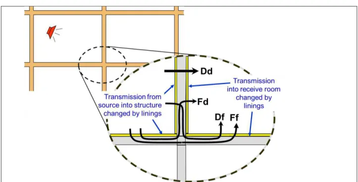
The calculations of ISO 15712-1 must deal with combination of the sound power transmitted via the direct path and a set of flanking paths. To discuss this, it is useful to introduce the convention for labelling the transmission paths that is used in ISO 15712-1, as explained in Figure 1.5.
Figure 1.5: This figure shows the labelling convention for transmission paths used in ISO 15712-1. Consider transmission from a source room at the left to the receiving room beside it. Each transmission path involves one surface in the source room (denoted by a capital letter) and one in the receive room (lower case). Direct
transmission through the separating wall is path Dd. For each edge of the separating assembly there are three flanking paths, each involving a surface in the source room and one in the receiving room, that connect at this edge: Ff from flanking surface F to flanking surface f, Df from direct surface D to flanking surface f, and Fd from flanking surface F to direct surface d in the receiving room.
Note that the lette F o f denotes fla ki g su fa e, a d D o d denotes the surface for direct transmission, i.e. - the surface of the separating assembly. These surfaces may be either wall or floor/ceiling assemblies, as detailed in the following Table 1.3.
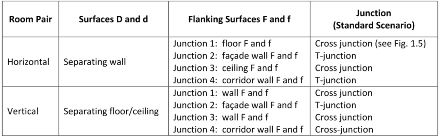
Room Pair Surfaces D and d Flanking Surfaces F and f Junction
(Standard Scenario)
Horizontal Separating wall
Junction 1: floor F and f Junction 2: façade wall F and f Junction 3: ceiling F and f Junction 4: corridor wall F and f
Cross junction (see Fig. 1.5) T-junction
Cross junction T-junction
Vertical Separating floor/ceiling
Junction 1: wall F and f
Junction 2: façade wall F and f Junction 3: wall F and f
Junction 4: corridor wall F and f
Cross junction T-junction Cross junction Cross-junction
Table 1.3: Surfaces (D, d, F and f) for flanking paths at each junction, as applied in the examples using the Standard Scenario in this Guide.
the separating assembly, as illustrated in Figure 1.5). Equation 14 in ISO 15712-1 is recast here with slightly different grouping of the paths (treating the set of paths at each edge of the separating assembly in turn) to match the presentation approach chosen for the examples in this Guide.
ASTC is determined from the apparent sound transmission loss (ATL) for the set of frequency bands from 125 to 4000 Hz, following the procedure in ASTM E413. ATL is the logarithmic expression of total transmission factor (’ as:
dB Equation 1.1
The total transmission factor (’) is calculated from a sum of transmission factors for individual paths:
Equation 1.2
where the indices Ff, Fd, and Df refer to the three flanking paths at each edge of the separating assembly, as illustrated in Figure 1.5.
The transmission factors are defined as follows:
’ is the ratio of total sound power radiated into the receiving room relative to sound power incident on the separating element;
Dd is the ratio of sound power radiated by the separating element relative to sound powerincident on the separating element;
Df is the ratio of sound power radiated by a flanking element f in the receiving room due tostructure-borne transmission from element D in the source room, relative to sound power incident on the separating element;
Ff is the ratio of sound power radiated by a flanking element f in the receiving room due tostructure-borne transmission from element F in the source room, relative to sound power incident on the separating element;
Fd is the ratio of sound power radiated by element d in the receiving room due tostructure-borne transmission from flanking element F in the source room, relative to sound power incident on the separating element;
Each of the transmission factors
ijcan be related to a corresponding path transmission loss associatedwith a specific pair of surfaces by the following expressions:
Direct transmission loss (for the separating assembly) dB
Flanking transmission loss (TL for flanking path ij) dB Equation 1.3
or conversely,
ijHe e the te s di e t t a s issio loss a d fla ki g t a s issio loss ha e ee defi ed to p o ide consistency with ASTM terminology, but match the function of the direct and flanking sound reduction index, as defined in ISO 15712-1, in keeping with the discussion of terms in Section 1.3. Each of these flanking transmission loss values for a specific path is normalized like the apparent sound transmission
loss, and can be considered as the ATL that would be observed if only this single path were contributing to the sound transmitted into the receiving room.
This list of transmission factors is less general than the corresponding list of transmission factors in ISO 15712-1 to reflect the simplifications due to the Standard Scenario (see Section 1.2 above) and some further simplifications noted in the following cautions.
Cautions and limitations to examples presented in this Guide:
This Guide was developed to support a proposed transition to ASTC ratings for sound control objectives of the National Building Code of Canada, and simplifications were made in the presentation to meet the specific needs of that application, where sound insulation is addressed only in the context of multi-unit residential buildings.
Transmission around or through the separating assembly, due to leaks at its perimeter or penetrations such as ventilation systems, are assumed negligible (and included in
Dd).
Indirect airborne transmission (for example airborne flanking via an unblocked attic or crawl space) is assumed to be insignificant.
Normalization of direct and flanking transmission to the case where receiving room absorption is numerically equal to the area of the separating assembly (i.e. - using apparent sound
transmission loss and ASTC as the measure of system performance) requires suitable corrections in the calculations of ISO 15712-1, or values of flanking transmission loss measured according to ISO 10848, so that the set of transmission factors or path transmission loss values can be properly combined or compared.
For adjacent occupancies in a multi-family residential building, the first two issues should be dealt with by normal good practice for fire and sound control between adjoining dwellings.
If this Guide is applied to situations other than separation between adjacent units in multi-family
residential buildings, some of these issues may have to be explicitly addressed in the calculation process. For example, for adjoining rooms within a single office or home, flanking paths such as ventilation ducts or open shared plenum spaces may be an issue. The flanking transmission associated with these
additional paths should be determined and included in the calculated ASTC. ISO 15712-1 includes specific guidance for such issues.
Where Normalised Flanking Level Difference (Dn,f) values measured according to ISO 10848 are to be
converted into Flanking Transmission Loss for these calculations, they must be re-normalized to reflect differences between the test situation and the prediction scenario. This also applies to laboratory results expressed as Flanking TL. The expressions to use in the calculation are:
in dB Eq. 1.4
in dB
Here Ssitu is area (in m2) of the separating assembly and lsitu is junction length (in m) for the prediction scenario, and Slab and llab are the corresponding values for the specimen in the ISO 10848 laboratory test. The expressions in Eq.1.4 apply for lightweight framed assemblies, as discussed in Chapter 4.
2. Buildings with Concrete or Masonry Walls and Concrete Floors
This chapter begins with an introduction outlining the concepts of the detailed calculation method of ISO 15712-1. Following sections provide more focussed procedural guidance and worked examples for specific sets of wall, floor, and junction details for concrete and masonry buildings.
Airborne sound in a source room excites vibration of the wall and floor assemblies that form the bounding surfaces of the room. As discussed in Chapter 1, the apparent transmission loss between adjacent rooms includes the combination of direct airborne transmission through the separating assembly and structure-borne flanking transmission via the three pairs of wall and floor surfaces (one in the source room and the other in the receiving room) that are connected at each of the four edges of the separating assembly. The detailed calculation process of ISO 15712-1 is focused on the balance between the input sound power and power losses (due to internal losses, sound radiation, and power flow into adjoining assemblies). This balance alters both direct transmission through each floor or wall assembly, and the strength of structure-borne transmission via the flanking surfaces.
For direct transmission through the separating assembly, the calculation process is shown in Figure 2.1, and the steps are described in more detail below. To transform the laboratory sound transmission data into the direct transmission loss in-situ requires a correction to adjust for the difference between losses in a laboratory test specimen and the losses when the assembly is connected to adjoining structures in-situ in the building.
Figure 2.1: Steps to calculate in-situ TL for the separating assembly (more details below) Step 1: Assemble required laboratory test data for constructions:
o Laboratory sound transmission loss (TL) values according to ASTM E90 for the structural floor or wall assembly of bare concrete or masonry without added linings (see Section 2.3.).
o Measured structural reverberation time ( TS) if available. ISO standards require measurement according to ISO 10848-1. Alternatively, a conservative estimate of total loss factor for a laboratory specimen from Eq. C.5 of Annex C of ISO 15712-1 may be used.
Step 2: Calculate edge losses for separating assembly in-situ:
o For each edge, calculate the vibration reduction index (Kij) between the separating assembly and each attached assembly using the appropriate case from Annex E of ISO 15712-1. These values depend on junction geometry and on the ratio of mass/area for the assemblies. o For each edge, calculate the resulting absorption coefficient, using the values of Kij and the
coincidence frequency (frequency at which the wavelength on the element and in surrounding air coincide) for the attached assemblies in Eq.C.2 of ISO 15712-1.
Step 4: Adjust lab. TL values Step 1: Assemble the
laboratory data for separating assembly:
TL values Structural RT
Step 3: Calculate total in-situ loss and structural RT for the separating assembly Step 2: Calculate edge losses for separating assembly In-situ TL values
Step 3: Calculate total loss for separating assembly and its in-situ structural reverberation time: o Use 2nd equation of Eq. C.1 of ISO 15712-1 to calculate the combination of internal losses,
radiation losses and edge losses. (Comparison between the values calculated for a common surface for a vertical pair of rooms and a horizontal pair of rooms gives a check on the loss calculations. The total loss is frequency-dependent for most junction types; the examples give only the value for 500 Hz band, to provide a benchmark value.)
o Use 1st equation of Eq. C.1 of ISO 15712-1 to calculate the resulting structural reverberation time of the assembly, for each frequency band.
Step 4: Calculate in-situ TL values for the separating assembly, using the ratio of structural reverberation times in Eq. 19 in Section 4.2.2 of ISO 15712-1.
For each flanking path, a similar procedure is required to deal with in-situ losses associated with the connecting junction and the two wall or floor surfaces that comprise the flanking path. The calculation process is presented in Figure 2.2, and each step is subsequently explained.
Figure 2.2: Steps to calculate flanking transmission loss for each flanking path (as detailed below) Step 5: Calculate in-situ TL values for each flanking assembly F in the source room, repeating the
procedure of Steps 1 – 4 for these assemblies.
Step 6: Calculate in-situ TL values for each flanking assembly f in the receiving room, by repeating the procedure of Steps 1 – 4 for these assemblies. (Note that because of the symmetry in the Standard Scenario used in this Guide, and because the preceding calculation for direct transmission provides in-situ values for surfaces D and d, Steps 5 and 6 in calculations for examples in this Guide required calculations for only two room surfaces: one floor/ceiling assembly and one flanking sidewall. The standard is more general.)
Step 7: Calculate in-situ velocity level difference (VLD) values for the junction attenuation:
o Calculate vibration reduction index (Kij) between the pair of assemblies using the appropriate case from Annex E of ISO 15712-1.
o Calculate VLD for junction using Eq. 21 and 22 of ISO 15712-1. Step 8: Calculate flanking TL values for each flanking path:
o Use VLD and in-situ TL values for the surfaces, in the calculation of Eq. 25a of ISO 15712-1. Step 5: Calculate in-situ TL
for each surface F in source room (as in Steps 1-4) Step 6: Calculate in-situ TL for each surface f in receiving room (as in Steps 1-4)
Step 7: Calculate KFf, KFd, and
KDf for each edge and adjust
to in-situ VLD value
Step 8: Calculate path TL for each flanking path, using in-situ values from Steps 5, 6 and 7 in Eq. 25a
Final Step: combine the sound power transmitted via the direct and flanking paths:
Step 9: Combine the sound power transmitted via the direct path through the separating assembly and the 12 flanking paths (3 at each edge of the separating assembly).
o Use Equations 1.1 to 1.3 in Section 1.4 of this Guide (equivalent to Section 4.1 of ISO 15712-1) to calculate Apparent TL.
o Use values of Apparent TL in procedure of ASTM E413 to calculate ASTC. From Step 4:
Take in-situ Direct TL values (including effect of linings)
From Step 8:
Take Flanking TL values (including effect of linings) for each flanking path
Step 9: Calculate Apparent TL using the equations in Section 1.4, and calculate ASTC from these values
2.1. Concrete and Masonry Buildings with Rigid Junctions
This section presents worked examples for the most basic sort of concrete and masonry building which has structural floor slabs of bare concrete and walls of bare concrete or masonry connecting at rigid
cross-junctions or T-junctions. He e a e is take to ea the asse l of o ete o aso
without a lining such as an added gypsum board finish on the walls or ceiling, or flooring over the concrete slab. The a e surface could be painted or sealed, or have a thin coat of plaster. The effect of adding a lining is discussed in detail in Section 2.3.
The calculations follow the steps of the ISO 15712-1 detailed calculation procedure, as described at the beginning of Chapter 2.
The app o i atio s of the al ulatio ake it ost suita le fo ho oge eous, lightl da ped structural elements whose coincidence frequency is below the frequency range of interest (taken here as below about 100 Hz). Typical floor and wall assemblies of concrete and masonry match these expectations.
Obviously, most buildings would have wall finishes (and usually also ceiling finishes) of gypsum board mounted on some sort of lightweight framing, and some sort of flooring over the concrete. The calculation extensions to deal with such li i gs are presented in Section 2.3. The examples in Section 2.1 and 2.2 have placeholders for including the effect of such linings, but those TL corrections have been set to zero.
The worked examples present all the pertinent physical characteristics of the assemblies and junctions, plus extracts from calculations performed with a more detailed spreadsheet that includes values for all the one-third-octave bands from 100 Hz to 5 kHz, and has intermediate steps in some calculations. The corresponding extracts present just the single-number ratings (such as ASTC and Path STC) and a subset of the calculated values for the frequency bands, to condense the examples to 2-page format. All examples conform to the Standard Scenario presented in Section 1.2 of this Guide.
The Refe e es olu p ese ts the sou e of i put data o i i g the NRC epo t u e a d
identifier for each laboratory test result or derived result), or identifies applicable equations and sections of ISO 15712-1 (2005) at each stage of the calculation. Symbols and subscripts identifying the corresponding variable in ISO 15712-1 are given in the adjacent column.
Under the headi g “TC, A“TC, et . the examples present single figure ratings (each calculated from a set of 1/3-octave data according to the rules for STC ratings defined in ASTM E413) to provide a consistent set of summary single-figure measures at each stage of the calculation. These include:
STC values for laboratory sound transmission loss data for wall or floor assemblies,
Δ“TC alues fo ha ge i “TC due to addi g a li i g to the specified wall or floor assembly, In-situ STC values for the calculated in-situ transmission loss of wall and floor assemblies, Direct STC for in-situ transmission through the separating assembly including linings, Flanking STC values calculated for each flanking transmission path at each junction, Apparent STC (ASTC) for the combination of direct and flanking transmission via all paths. Validation studies [13] in Europe for such constructions have confirmed that these detailed predictions should be expected to exhibit a standard deviation of about 1.5 dB, with negligible bias, relative to measured values in actual buildings with these characteristics.
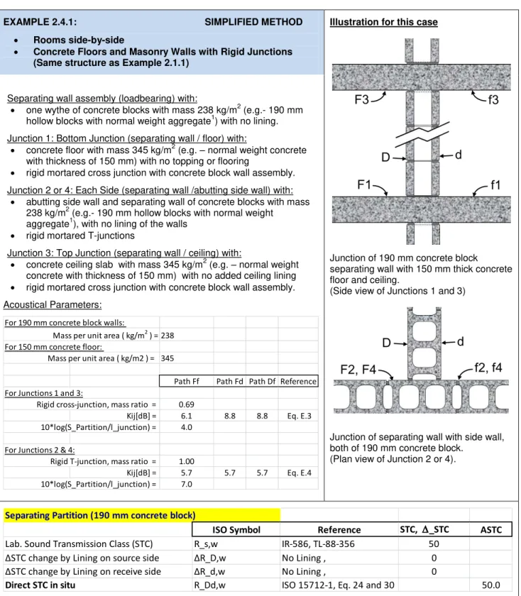
EXAMPLE 2.1.1:
Rooms side-by-side
Concrete Floors and Masonry Walls with Rigid Junctions
Illustration for this case
Junction of 190 mm concrete block separating wall with 150 mm thick concrete floor and ceiling.
(Side view of Junctions 1 and 3)
Junction of separating wall with side wall, both of 190 mm concrete block.
(Plan view of Junction 2 or 4). Separating wall assembly (loadbearing) with:
one wythe of concrete blocks with mass 238 kg/m2
(e.g.- 190 mm hollow blocks with normal weight aggregate1) with no lining. Junction 1: Bottom Junction (separating wall / floor) with:
concrete floor with mass 345 kg/m2 (e.g. – normal weight concrete
with thickness of 150 mm) with no topping or flooring
rigid mortared cross junction with concrete block wall assembly. Junction 2 or 4: Each Side (separating wall /abutting side wall) with:
abutting side wall and separating wall of concrete blocks with mass 238 kg/m2 (e.g.- 190 mm hollow blocks with normal weight
aggregate1), with no lining rigid mortared T-junctions
Junction 3: Top Junction (separating wall / ceiling) with:
concrete ceiling slab with mass 345 kg/m2 (e.g. – normal weight
concrete with thickness of 150 mm) with no added ceiling lining rigid mortared cross junction with concrete block wall assembly. Acoustical Parameters:
(See footnotes at end of document)
For separating assembly:
i te al loss, η_i = 0.015 c_L = 3500 mass (kg/m²) = 237.5 f_c = 98
Reference K_13 K_12 K_14 Σ l_k . α_k X-Junction 1 or 3 ISO 15712-1, Eq. E.3 11.6 8.8 8.8 0.566 T-Junction 2 or 4 ISO 15712-1, Eq. E.4 5.7 5.7 0.420 Total loss, η_tot ISO 15712-1, Eq. C.1 0.041 (Eq. C.2)
(at 500 Hz) Similarly, for flanking elements F and f at Junction 1 & 3,
i te al loss, η_i = 0.006 c_L = 3500 mass (kg/m²) = 345 f_c = 124
Total loss, η_tot ISO 15712-1, Eq. C.1 0.028 (at 500 Hz) Similarly, for flanking elements F and f at Junction 2 & 4,
i te al loss, η_i = 0.015 c_L = 3500 mass (kg/m²) = 238 f_c = 98
Total loss, η_tot, ISO 15712-1, Eq. C.1 0.047 (at 500 Hz) Total loss, η_tot, ISO 15712-1, Eq. C.1 0.043 (at 500 Hz) Separating Partition (190 mm concrete block)
Input Data ISO Symbol Reference STC, ASTC,etc. 125 250 500 1000 2000 4000
Sound Transmission Loss R_D,lab IR-586, TL-88-356 50 33 41.2 44 50.4 57 63.9 Structural Reverberation Time T_s,lab ISO 15712-1, Eq. C.5 0.30 0.19 0.12 0.07 0.04 0.02
Radiation Efficiency 1 1 1 1 1 1
Change by Lining on source side ΔR_D No Lining , 0 0 0 0 0 0 0
Change by Lining on receive side ΔR_d No Lining , 0 0 0 0 0 0 0
Transferred Data - In-situ
Structural Reverberation time T_s,situ ISO 15712-1, Eq. C.1-C.3 0.257 0.169 0.108 0.067 0.040 0.023 Equivalent Absorption Length alpha_D,situ ISO 15712-1, Eq. 22 8.8 9.4 10.4 12.0 14.2 17.3
Junction 1 (Rigid Cross junction, 190 mm block separating wall / 150 mm concrete floor)
Flanking Element F1 and f1: Input ISO Symbol Reference STC, ASTC,etc. 125 250 500 1000 2000 4000
Sound Transmission Loss R_F1,lab IR-811, TLF-97-107a 52 39.0 39.0 49.0 58.0 67.0 76.0 Structural Reverberation Time T_s,lab Measured T_s 0.345 0.293 0.176 0.092 0.046 0.042 Radiation Efficiency σ 1.00 1.00 1.00 1.00 1.00 1.00 Change by Lining on source side ΔR_F1 No Lining , 0 0.0 0.0 0.0 0.0 0.0 0.0 Change by Lining on receive side ΔR_f1 No Lining , 0 0.0 0.0 0.0 0.0 0.0 0.0 Flanking Element F1 and f1: Transferred Data - In-situ
Structural Reverberation time T_s,situ ISO 15712-1, Eq. C.1-C.3 0.348 0.238 0.160 0.104 0.066 0.041 Equivalent Absorption Length alpha_situ ISO 15712-1, Eq. 22 10.395 10.724 11.318 12.247 13.626 15.621 TL in situ for F1 R_F1,situ ISO 15712-1, Eq. 19 53 39.0 39.9 49.4 57.4 65.4 76.1 TL in situ for f1 R_f1,situ ISO 15712-1, Eq. 19 53 39.0 39.9 49.4 57.4 65.4 76.1 Junction J1 - Coupling
Velocity Level Difference for Ff D_v,Ff_1,situ ISO 15712-1, Eq. 21 9.26 9.39 9.62 9.97 10.43 11.02 Velocity Level Difference for Fd D_v,Fd_1,situ ISO 15712-1, Eq. 21 11.67 11.88 12.22 12.69 13.29 14.02 Velocity Level Difference for Df D_v,Df_1,situ ISO 15712-1, Eq. 21 11.67 11.88 12.22 12.69 13.29 14.02 Flanking Transmission Loss - Path data
Flanking TL for Path Ff_1 R_Ff ISO 15712-1, Eq. 25a 60 46.2 47.3 57.0 65.4 73.8 85.1 Flanking TL for Path Fd_1 R_Fd ISO 15712-1, Eq. 25a 63 47.0 51.7 58.1 65.8 73.6 83.1 Flanking TL for Path Df_1 R_Df ISO 15712-1, Eq. 25a 63 47.0 51.7 58.1 65.8 73.6 83.1
Junction 2 (Rigid T-Junction, 190 mm block separating wall / 190 mm block flanking wall)
Flanking Element F2 and f2: Input Data
Sound Transmission Loss R_F2,lab IR-586, TL-88-356 50 33.0 41.2 44.0 50.4 57.0 63.9 Structural Reverberation Time T_s,lab ISO 15712-1, Eq. C.5 0.299 0.191 0.119 0.072 0.042 0.024 Radiation Efficiency σ 1.00 1.00 1.00 1.00 1.00 1.00 Change by Lining on source side ΔR_F2 No Lining , 0 0.0 0.0 0.0 0.0 0.0 0.0 Change by Lining on receive side ΔR_f2 No Lining , 0 0.0 0.0 0.0 0.0 0.0 0.0 Flanking Element F2 and f2: Transferred Data - In-situ
Structural Reverberation time T_s,situ ISO 15712-1, Eq. C.1-C.3 0.219 0.146 0.094 0.059 0.036 0.021 Equivalent Absorption Length alpha_situ ISO 15712-1, Eq. 22 8.250 8.756 9.565 10.774 12.532 15.049 TL in situ for F2 R_F2,situ ISO 15712-1, Eq. 19 51 34.4 42.4 45.0 51.3 57.7 64.5 TL in situ for f2 R_f2,situ ISO 15712-1, Eq. 19 51 34.4 42.4 45.0 51.3 57.7 64.5 Junction J2 - Coupling
Velocity Level Difference for Ff D_v,Ff_2,situ ISO 15712-1, Eq. 21 10.89 11.14 11.53 12.04 12.70 13.50 Velocity Level Difference for Fd D_v,Fd_2,situ ISO 15712-1, Eq. 21 11.02 11.31 11.72 12.27 12.96 13.80 Velocity Level Difference for Df D_v,Df_2,situ ISO 15712-1, Eq. 21 11.02 11.31 11.72 12.27 12.96 13.80 Flanking Transmission Loss - Path data
Flanking TL for Path Ff_2 R_Ff ISO 15712-1, Eq. 25a 63 46.2 54.5 57.5 64.3 71.4 78.9 Flanking TL for Path Fd_2 R_Fd ISO 15712-1, Eq. 25a 63 45.5 53.8 56.9 63.8 70.9 78.6 Flanking TL for Path Df_2 R_Df ISO 15712-1, Eq. 25a 63 45.5 53.8 56.9 63.8 70.9 78.6
Junction 3 (Rigid Cross junction, 190 mm block separating wall / 150 mm concrete ceiling slab)
All values the same as for Junction 1
Junction 4 (Rigid T-junction, 190 mm block separating wall / 190 mm block flanking wall)
All input data the same as for Junction 2
Flanking Element F4 and f4: Transferred Data - In-situ (different junctions at ceiling and floor change loss factors from junction 2)
Structural Reverberation time T_s,situ ISO 15712-1, Eq. C.1-C.3 0.238 0.158 0.102 0.063 0.038 0.021 Equivalent Absorption Length alpha_situ ISO 15712-1, Eq. 22 7.577 8.083 8.892 10.102 11.859 14.377 TL in situ for F4 R_F4,situ ISO 15712-1, Eq. 19 50 34.0 42.0 44.7 51.0 57.5 64.3 TL in situ for f4 R_f4,situ ISO 15712-1, Eq. 19 50 34.0 42.0 44.7 51.0 57.5 64.3 Junction J4 - Coupling
Velocity Level Difference for Ff D_v,Ff_4,situ ISO 15712-1, Eq. 21 10.52 10.80 11.21 11.76 12.46 13.30 Velocity Level Difference for Fd D_v,Fd_4,situ ISO 15712-1, Eq. 21 10.84 11.13 11.56 12.13 12.84 13.70 Velocity Level Difference for Df D_v,Df_4,situ ISO 15712-1, Eq. 21 10.84 11.13 11.56 12.13 12.84 13.70 Flanking Transmission Loss - Path data
Flanking TL for Path Ff_4 R_Ff ISO 15712-1, Eq. 25a 63 45.5 53.8 56.9 63.7 70.9 78.5 Flanking TL for Path Fd_4 R_Fd ISO 15712-1, Eq. 25a 62 45.2 53.5 56.6 63.5 70.7 78.4 Flanking TL for Path Df_4 R_Df ISO 15712-1, Eq. 25a 62 45.2 53.5 56.6 63.5 70.7 78.4
Total Flanking STC (combined transmission for all flanking paths) 51
EXAMPLE 2.1.2:
Rooms one-above-the-other
Concrete Floor and Masonry Walls with Rigid Junctions
Illustration for this case
Cross junction of separating floor of 150 mm thick concrete with 190 mm concrete block wall. (Side view of Junctions 1, 3, 4)
T-Junction of separating floor of 150 mm thick concrete floor with 190 mm concrete block wall. (Side view of Junction 2). Separating floor/ceiling assembly with:
concrete floor with mass 345 kg/m2 (e.g. – normal weight concrete
with thickness of 150 mm) with no topping / flooring on top, or ceiling lining below.
Junction 1, 3, 4: Cross Junction of separating floor / flanking wall with: rigid mortared cross junction with concrete block wall assemblies. wall above and below floor of one wythe of concrete blocks with
mass 238 kg/m2 (e.g. - 190 mm hollow blocks with normal weight aggregate1) with no lining of walls.
Junction 2: T-Junction of separating floor / flanking wall with: rigid mortared T-junctions with concrete block wall assemblies wall above and below floor of one wythe of concrete blocks with
mass 238 kg/m2 (e.g. - 190 mm hollow blocks with normal weight aggregate1) with no lining of walls.
Acoustical Parameters:
(See footnotes at end of document)
For separating assembly:
i te al loss, η_i = 0.006 c_L = 3500 mass (kg/m²) = 345 f_c = 124
Reference K_13 K_12 K_14 Σ l_k . α_k X-Junction 1, 3, 4 ISO 15712-1, Eq. E.3 6.1 8.8 8.8 0.841
T-Junction 2 ISO 15712-1, Eq. E.4 5.8 5.8 0.650 Total loss, η_tot ISO 15712-1, Eq. C.1 0.028 (Eq. C.2)
(at 500 Hz) Similarly, for flanking elements F and f at Junction 1 & 3,
i te al loss, η_i = 0.015 c_L = 3500 mass (kg/m²) = 238 f_c = 98
Total loss, η_tot ISO 15712-1, Eq. C.1 0.041 (at 500 Hz) Similarly, for flanking elements F and f at Junction 2 & 4,
i te al loss, η_i = 0.015 c_L = 3500 mass (kg/m²) = 238 f_c = 98
Total loss, η_tot, ISO 15712-1, Eq. C.1 0.047 (at 500 Hz) Total loss, η_tot, ISO 15712-1, Eq. C.1 0.043 (at 500 Hz)
Separating Partition (150 mm concrete floor)
Input Data ISO Symbol Reference STC, ASTC, etc. 125 250 500 1000 2000 4000
Sound Transmission Loss R_D,lab IR-811, TLF-97-107a 52 39 39 49 58 67 76 Structural Reverberation Time T_s,lab Measured T_s 0.35 0.29 0.18 0.09 0.05 0.04
Radiation Efficiency 1 1 1 1 1 1
Change by Lining on source side ΔR_D No lining , 0 0 0 0 0 0 0
Change by Lining on receive side ΔR_d No lining , 0 0 0 0 0 0 0
Transferred Data - In-situ
Structural Reverberation time T_s,situ ISO 15712-1, Eq. C.1-C.3 0.348 0.238 0.160 0.104 0.066 0.041 Equivalent Absorption Length alpha_D,situ ISO 15712-1, Eq. 22 10.4 10.7 11.3 12.2 13.6 15.6
Junction 1 (Rigid Cross junction, 150 mm concrete floor / 190 mm block flanking wall)
Flanking Element F1 and f1: Input ISO Symbol Reference STC, ASTC, etc. 125 250 500 1000 2000 4000
Sound Transmission Loss R_F1,lab IR-586, TL-88-356 50 33.0 41.2 44.0 50.4 57.0 63.9 Structural Reverberation Time T_s,lab Estimate Eq. C.5 0.299 0.191 0.119 0.072 0.042 0.024 Radiation Efficiency σ 1.00 1.00 1.00 1.00 1.00 1.00 Change by Lining on source side ΔR_F1 No lining , 0 0.0 0.0 0.0 0.0 0.0 0.0 Change by Lining on receive side ΔR_f1 No lining , 0 0.0 0.0 0.0 0.0 0.0 0.0 Flanking Element F1 and f1: Transferred Data - In-situ
Structural Reverberation time T_s,situ ISO 15712-1, Eq. C.1-C.3 0.257 0.169 0.108 0.067 0.040 0.023 Equivalent Absorption Length alpha_situ ISO 15712-1, Eq. 22 8.799 9.431 10.442 11.954 14.151 17.298 TL in situ for F1 R_F1,situ ISO 15712-1, Eq. 19 50 33.7 41.7 44.4 50.7 57.3 64.1 TL in situ for f1 R_f1,situ ISO 15712-1, Eq. 19 50 33.7 41.7 44.4 50.7 57.3 64.1 Junction J1 - Coupling
Velocity Level Difference for Ff D_v,Ff_1,situ ISO 15712-1, Eq. 21 14.08 14.38 14.82 15.41 16.14 17.01 Velocity Level Difference for Fd D_v,Fd_1,situ ISO 15712-1, Eq. 21 11.67 11.88 12.22 12.69 13.29 14.02 Velocity Level Difference for Df D_v,Df_1,situ ISO 15712-1, Eq. 21 11.67 11.88 12.22 12.69 13.29 14.02 Flanking Transmission Loss - Path data
Flanking TL for Path Ff_1 R_Ff ISO 15712-1, Eq. 25a 67 49.8 58.2 61.3 68.2 75.4 83.2 Flanking TL for Path Fd_1 R_Fd ISO 15712-1, Eq. 25a 65 49.0 53.7 60.2 67.8 75.6 85.2 Flanking TL for Path Df_1 R_Df ISO 15712-1, Eq. 25a 65 49.0 53.7 60.2 67.8 75.6 85.2
Junction 2 (Rigid T-Junction, 150 mm concrete floor / 190 mm block flanking wall)
Flanking Element F2 and f2: Input Data
Sound Transmission Loss R_F2,lab IR-586, TL-88-356 50 33.0 41.2 44.0 50.4 57.0 63.9 Structural Reverberation Time T_s,lab Estimate Eq. C.5 0.299 0.191 0.119 0.072 0.042 0.024 Radiation Efficiency σ 1.00 1.00 1.00 1.00 1.00 1.00 Change by Lining on source side ΔR_F2 No lining , 0 0.0 0.0 0.0 0.0 0.0 0.0 Change by Lining on receive side ΔR_f2 No lining , 0 0.0 0.0 0.0 0.0 0.0 0.0 Flanking Element F2 and f2: Transferred Data - In-situ
Structural Reverberation time T_s,situ ISO 15712-1, Eq. C.1-C.3 0.219 0.146 0.094 0.059 0.036 0.021 Equivalent Absorption Length alpha_situ ISO 15712-1, Eq. 22 8.250 8.756 9.565 10.774 12.532 15.049 TL in situ for F2 R_F2,situ ISO 15712-1, Eq. 19 51 34.4 42.4 45.0 51.3 57.7 64.5 TL in situ for f2 R_f2,situ ISO 15712-1, Eq. 19 51 34.4 42.4 45.0 51.3 57.7 64.5 Junction J2 - Coupling
Velocity Level Difference for Ff D_v,Ff_2,situ ISO 15712-1, Eq. 21 11.28 11.54 11.92 12.44 13.10 13.89 Velocity Level Difference for Fd D_v,Fd_2,situ ISO 15712-1, Eq. 21 9.50 9.69 10.00 10.43 10.99 11.69 Velocity Level Difference for Df D_v,Df_2,situ ISO 15712-1, Eq. 21 9.50 9.69 10.00 10.43 10.99 11.69 Flanking Transmission Loss - Path data
Flanking TL for Path Ff_2 R_Ff ISO 15712-1, Eq. 25a 66 48.6 56.9 59.9 66.7 73.8 81.4 Flanking TL for Path Fd_2 R_Fd ISO 15712-1, Eq. 25a 63 47.7 52.3 58.7 66.3 74.0 83.5 Flanking TL for Path Df_2 R_Df ISO 15712-1, Eq. 25a 63 47.7 52.3 58.7 66.3 74.0 83.5
Junction 3 (Rigid Cross junction, 150 mm concrete ceiling / 190 mm block flanking wall)
All values the same as for Junction 1
Junction 4 (Rigid Cross-Junction, 150 mm concrete floor / 190 mm block flanking wall)
All input data the same as for Junction 2, but different junctions at ceiling and floor change loss factors and junction attenuation from Junction 2 Flanking Element F4 and f4: Transferred Data - In-situ
Structural Reverberation time T_s,situ ISO 15712-1, Eq. C.1-C.3 0.238 0.158 0.102 0.063 0.038 0.021 Equivalent Absorption Length alpha_situ ISO 15712-1, Eq. 22 7.577 8.083 8.892 10.102 11.859 14.377 TL in situ for F4 R_F4,situ ISO 15712-1, Eq. 19 50 34.0 42.0 44.7 51.0 57.5 64.3 TL in situ for f4 R_f4,situ ISO 15712-1, Eq. 19 50 34.0 42.0 44.7 51.0 57.5 64.3 Junction J4 - Coupling
Velocity Level Difference for Ff D_v,Ff_4,situ ISO 15712-1, Eq. 21 14.40 14.68 15.09 15.65 16.34 17.18 Velocity Level Difference for Fd D_v,Fd_4,situ ISO 15712-1, Eq. 21 12.31 12.52 12.84 13.29 13.87 14.59 Velocity Level Difference for Df D_v,Df_4,situ ISO 15712-1, Eq. 21 12.31 12.52 12.84 13.29 13.87 14.59 Flanking Transmission Loss - Path data
Flanking TL for Path Ff_4 R_Ff ISO 15712-1, Eq. 25a 68 51.4 59.7 62.8 69.6 76.8 84.5 Flanking TL for Path Fd_4 R_Fd ISO 15712-1, Eq. 25a 66 50.3 55.0 61.4 69.0 76.8 86.3 Flanking TL for Path Df_4 R_Df ISO 15712-1, Eq. 25a 66 50.3 55.0 61.4 69.0 76.8 86.3
Total Flanking STC (combined transmission for all flanking paths) 54
EXAMPLE 2.1.3:
Rooms side-by-side
Concrete Floors and Concrete Walls with Rigid Junctions
Illustration for this case
Junctions of 150 mm concrete separating wall with 150 mm thick concrete floor and ceiling. (Side view of Junctions 1 and 3)
Junction of separating wall with side wall, both of 150 mm concrete. (Plan view of Junction 2 or 4) Separating wall assembly (loadbearing) with:
solid concrete with mass 345 kg/m2 (e.g. – normal weight concrete
with thickness of 150 mm) with no lining on either side. Junction 1: Bottom Junction (separating wall / floor) with:
concrete floor with mass 460 kg/m2 (e.g. – normal weight concrete
with thickness of 200 mm) with no topping or flooring rigid cross junction with concrete wall assembly.
Junction 2 or 4: Each Side (separating wall /abutting side wall) with: abutting side wall and separating wall of solid concrete with mass
345 kg/m2 (e.g. – normal weight concrete with thickness of 150 mm), with no lining
rigid T-junctions
Junction 3: Top Junction (separating wall / ceiling) with:
concrete ceiling slab with mass 460 kg/m2 (e.g. – normal weight
concrete with thickness of 200 mm) with no added ceiling lining rigid cross junction with concrete wall assembly.
Acoustical Parameters:
(See footnotes at end of document)
For separating assembly:
i te al loss, η_i = 0.006 c_L = 3500 mass (kg/m²) = 345 f_c = 124
Reference K_13 K_12 K_14 Σ l_k . α_k X-Junction 1 or 3 ISO 15712-1, Eq. E.3 10.9 8.8 8.8 0.544 T-Junction 2 or 4 ISO 15712-1, Eq. E.4 5.7 5.7 0.473 Total loss, η_tot ISO 15712-1, Eq. C.1 0.0293 (Eq. C.2)
(at 500 Hz) Similarly, for flanking elements F and f at Junction 1 & 3,
i te al loss, η_i = 0.006 c_L = 3500 mass (kg/m²) = 460 f_c = 93
Total loss, η_tot ISO 15712-1, Eq. C.1 0.0303 (at 500 Hz) Similarly, for flanking elements F and f at Junction 2 & 4,
i te al loss, η_i = 0.006 c_L = 3500 mass (kg/m²) = 345 f_c = 124
Total loss, η_tot, ISO 15712-1, Eq. C.1 0.0356 (at 500 Hz) Total loss, η_tot, ISO 15712-1, Eq. C.1 0.0319 (at 500 Hz)
Separating Partition (150 mm concrete)
Input Data ISO Symbol Reference STC, ASTC,etc. 125 250 500 1000 2000 4000
Sound Transmission Loss R_D,lab IR-811, TLF-97-107a 52 39 39 49 58 67 76 Structural Reverberation Time T_s,lab Measured T_s 0.35 0.29 0.18 0.09 0.05 0.04
Radiation Efficiency 1 1 1 1 1 1
Change by Lining on source side ΔR_D No Lining , 0 0 0 0 0 0 0 Change by Lining on receive side ΔR_d No Lining , 0 0 0 0 0 0 0 Transferred Data - In-situ
Structural Reverberation time T_s,situ ISO 15712-1, Eq. C.1-C.3 0.325 0.223 0.150 0.099 0.063 0.039 Equivalent Absorption Length alpha_D,situ ISO 15712-1, Eq. 22 6.9 7.2 7.5 8.1 9.0 10.2
Junction 1 (Rigid Cross junction, 150 mm concrete separating wall / 200 mm concrete floor)
Flanking Element F1 and f1: Input ISO Symbol Reference STC, ASTC,etc. 125 250 500 1000 2000 4000
Sound Transmission Loss R_F1,lab TLF-12-013 58 41.8 47.9 54.6 59.8 66.8 70.2 Structural Reverberation Time T_s,lab Measured T_s 0.176 0.115 0.109 0.108 0.080 0.076 Radiation Efficiency σ 1.00 1.00 1.00 1.00 1.00 1.00 Change by Lining on source side ΔR_F1 No Lining , 0 0.0 0.0 0.0 0.0 0.0 0.0 Change by Lining on receive side ΔR_f1 No Lining , 0 0.0 0.0 0.0 0.0 0.0 0.0 Flanking Element F1 and f1: Transferred Data - In-situ
Structural Reverberation time T_s,situ ISO 15712-1, Eq. C.1-C.3 0.316 0.216 0.145 0.095 0.061 0.038 Equivalent Absorption Length alpha_situ ISO 15712-1, Eq. 22 11.430 11.804 12.430 13.382 14.777 16.784 TL in situ for F1 R_F1,situ ISO 15712-1, Eq. 19 56 39.3 45.1 53.3 60.3 67.9 73.2 TL in situ for f1 R_f1,situ ISO 15712-1, Eq. 19 56 39.3 45.1 53.3 60.3 67.9 73.2 Junction J1 - Coupling
Velocity Level Difference for Ff D_v,Ff_1,situ ISO 15712-1, Eq. 21 10.24 10.38 10.61 10.93 11.36 11.91 Velocity Level Difference for Fd D_v,Fd_1,situ ISO 15712-1, Eq. 21 11.30 11.43 11.65 11.97 12.41 12.97 Velocity Level Difference for Df D_v,Df_1,situ ISO 15712-1, Eq. 21 11.30 11.43 11.65 11.97 12.41 12.97 Flanking Transmission Loss - Path data
Flanking TL for Path Ff_1 R_Ff ISO 15712-1, Eq. 25a 65 47.5 53.5 61.9 69.2 77.3 83.1 Flanking TL for Path Fd_1 R_Fd ISO 15712-1, Eq. 25a 65 49.5 53.1 62.2 70.0 78.2 86.7 Flanking TL for Path Df_1 R_Df ISO 15712-1, Eq. 25a 65 49.5 53.1 62.2 70.0 78.2 86.7
Junction 2 (Rigid T-Junction, 150 mm concrete separating wall / 150 mm concrete flanking wall)
Flanking Element F2 and f2: Input Data
Sound Transmission Loss R_F2,lab IR-811, TLF-97-107a 52 39.0 39.0 49.0 58.0 67.0 76.0 Structural Reverberation Time T_s,lab Measured T_s 0.345 0.293 0.176 0.092 0.046 0.042 Radiation Efficiency σ 1.00 1.00 1.00 1.00 1.00 1.00 Change by Lining on source side ΔR_F2 No Lining , 0 0.0 0.0 0.0 0.0 0.0 0.0 Change by Lining on receive side ΔR_f2 No Lining , 0 0.0 0.0 0.0 0.0 0.0 0.0 Flanking Element F2 and f2: Transferred Data - In-situ
Structural Reverberation time T_s,situ ISO 15712-1, Eq. C.1-C.3 0.264 0.182 0.124 0.082 0.053 0.034 Equivalent Absorption Length alpha_situ ISO 15712-1, Eq. 22 6.849 7.014 7.311 7.776 8.465 9.463 TL in situ for F2 R_F2,situ ISO 15712-1, Eq. 19 54 40.2 41.1 50.5 58.5 66.3 77.0 TL in situ for f2 R_f2,situ ISO 15712-1, Eq. 19 54 40.2 41.1 50.5 58.5 66.3 77.0 Junction J2 - Coupling
Velocity Level Difference for Ff D_v,Ff_2,situ ISO 15712-1, Eq. 21 10.08 10.18 10.36 10.63 11.00 11.48 Velocity Level Difference for Fd D_v,Fd_2,situ ISO 15712-1, Eq. 21 10.11 10.22 10.42 10.72 11.12 11.65 Velocity Level Difference for Df D_v,Df_2,situ ISO 15712-1, Eq. 21 10.11 10.22 10.42 10.72 11.12 11.65 Flanking Transmission Loss - Path data
Flanking TL for Path Ff_2 R_Ff ISO 15712-1, Eq. 25a 65 51.2 52.2 61.9 70.1 78.3 89.4 Flanking TL for Path Fd_2 R_Fd ISO 15712-1, Eq. 25a 64 50.3 51.3 61.0 69.3 77.6 88.8 Flanking TL for Path Df_2 R_Df ISO 15712-1, Eq. 25a 64 50.3 51.3 61.0 69.3 77.6 88.8
Junction 3 (Rigid Cross junction, 150 mm concrete separating wall / 200 mm concrete ceiling slab)
All values the same as for Junction 1
Junction 4 (Rigid T-junction, 150 mm concrete separating wall / 150 mm concrete flanking wall)
All input data the same as for Junction 2
Flanking Element F4 and f4: Transferred Data - In-situ (different junctions at ceiling and floor change loss factors from junction 2)
Structural Reverberation time T_s,situ ISO 15712-1, Eq. C.1-C.3 0.296 0.204 0.138 0.091 0.059 0.034 Equivalent Absorption Length alpha_situ ISO 15712-1, Eq. 22 6.094 6.259 6.555 7.020 7.710 8.707 TL in situ for F4 R_F4,situ ISO 15712-1, Eq. 19 53 39.7 40.6 50.1 58.0 65.9 76.6 TL in situ for f4 R_f4,situ ISO 15712-1, Eq. 19 53 39.7 40.6 50.1 58.0 65.9 76.6 Junction J4 - Coupling
Velocity Level Difference for Ff D_v,Ff_4,situ ISO 15712-1, Eq. 21 9.57 9.69 9.89 10.18 10.59 11.12 Velocity Level Difference for Fd D_v,Fd_4,situ ISO 15712-1, Eq. 21 9.85 9.97 10.19 10.50 10.92 11.47 Velocity Level Difference for Df D_v,Df_4,situ ISO 15712-1, Eq. 21 9.85 9.97 10.19 10.50 10.92 11.47 Flanking Transmission Loss - Path data
Flanking TL for Path Ff_4 R_Ff ISO 15712-1, Eq. 25a 64 50.2 51.2 60.9 69.2 77.5 88.7 Flanking TL for Path Fd_4 R_Fd ISO 15712-1, Eq. 25a 64 49.8 50.8 60.5 68.8 77.2 88.4 Flanking TL for Path Df_4 R_Df ISO 15712-1, Eq. 25a 64 49.8 50.8 60.5 68.8 77.2 88.4
Total Flanking STC (combined transmission for all flanking paths) 54
EXAMPLE 2.1.4:
Rooms one-above-the-other
Concrete Floor and Concrete Walls with Rigid Junctions
Illustration for this case
Cross junction of separating floor of 200 mm thick concrete with 150 mm thick concrete wall.
(Side view of Junctions 1, 3 or 4)
T-Junction of separating floor of 200 mm thick concrete floor with 150 mm thick concrete wall. (Side view of Junction 2) Separating floor/ceiling assembly with:
concrete floor with mass 460 kg/m2 (e.g. – normal weight concrete
with thickness of 200 mm) with no topping / flooring on top, or ceiling lining below.
Junction 1, 3, 4: Cross Junction of separating floor / flanking wall with: rigid cross junction with concrete wall assemblies.
wall above and below floor of solid concrete with mass 345 kg/m2
(e.g. – normal weight concrete with thickness of 150 mm) with no lining of walls.
Junction 2: T-Junction of separating floor / flanking wall with: rigid T-junctions with concrete wall assemblies
wall above and below floor of solid concrete with mass 345 kg/m2
(e.g. – normal weight concrete with thickness of 150 mm) with no lining of walls.
Acoustical Parameters:
(See footnotes at end of document)
For separating assembly:
i te al loss, η_i = 0.006 c_L = 3500 mass (kg/m²) = 460 f_c = 93
Reference K_13 K_12 K_14 Σ l_k . α_k X-Junction 1, 3, 4 ISO 15712-1, Eq. E.3 6.7 8.8 8.8 0.794
T-Junction 2 ISO 15712-1, Eq. E.4 5.8 5.8 0.742 Total loss, η_tot ISO 15712-1, Eq. C.1 0.0303 (Eq. C.2)
(at 500 Hz) Similarly, for flanking elements F and f at Junction 1 & 3,
i te al loss, η_i = 0.006 c_L = 3500 mass (kg/m²) = 345 f_c = 124
Total loss, η_tot ISO 15712-1, Eq. C.1 0.0293 (at 500 Hz) Similarly, for flanking elements F and f at Junction 2 & 4,
i te al loss, η_i = 0.006 c_L = 3500 mass (kg/m²) = 345 f_c = 124
Total loss, η_tot, ISO 15712-1, Eq. C.1 0.0356 (at 500 Hz) Total loss, η_tot, ISO 15712-1, Eq. C.1 0.0319 (at 500 Hz)
Separating Partition (200 mm concrete floor)
Input Data ISO Symbol Reference STC, ASTC, etc. 125 250 500 1000 2000 4000
Sound Transmission Loss R_D,lab TLF-12-013 58 41.8 47.9 54.6 59.8 66.8 70.2 Structural Reverberation Time T_s,lab Measured T_s 0.18 0.11 0.11 0.11 0.08 0.08
Radiation Efficiency 1 1 1 1 1 1
Change by Lining on source side ΔR_D No lining , 0 0 0 0 0 0 0 Change by Lining on receive side ΔR_d No lining , 0 0 0 0 0 0 0 Transferred Data - In-situ
Structural Reverberation time T_s,situ ISO 15712-1, Eq. C.1-C.3 0.316 0.216 0.145 0.095 0.061 0.038 Equivalent Absorption Length alpha_D,situ ISO 15712-1, Eq. 22 11.4 11.8 12.4 13.4 14.8 16.8