Publisher’s version / Version de l'éditeur:
Metal Magazine, 7, September 6, pp. 122-128, 130-131, 2006-09-01
READ THESE TERMS AND CONDITIONS CAREFULLY BEFORE USING THIS WEBSITE. https://nrc-publications.canada.ca/eng/copyright
Vous avez des questions? Nous pouvons vous aider. Pour communiquer directement avec un auteur, consultez la
première page de la revue dans laquelle son article a été publié afin de trouver ses coordonnées. Si vous n’arrivez pas à les repérer, communiquez avec nous à [email protected].
Questions? Contact the NRC Publications Archive team at
[email protected]. If you wish to email the authors directly, please see the first page of the publication for their contact information.
NRC Publications Archive
Archives des publications du CNRC
This publication could be one of several versions: author’s original, accepted manuscript or the publisher’s version. / La version de cette publication peut être l’une des suivantes : la version prépublication de l’auteur, la version acceptée du manuscrit ou la version de l’éditeur.
Access and use of this website and the material on it are subject to the Terms and Conditions set forth at
A Complex phenomenon : dynamic wind uplift performance of
composite metal roofing assemblies
Baskaran, B. A.; Nabhan, F.; Molleti, S.
https://publications-cnrc.canada.ca/fra/droits
L’accès à ce site Web et l’utilisation de son contenu sont assujettis aux conditions présentées dans le site LISEZ CES CONDITIONS ATTENTIVEMENT AVANT D’UTILISER CE SITE WEB.
NRC Publications Record / Notice d'Archives des publications de CNRC: https://nrc-publications.canada.ca/eng/view/object/?id=11db9fd6-a6f8-4086-965d-54ff6547f76b https://publications-cnrc.canada.ca/fra/voir/objet/?id=11db9fd6-a6f8-4086-965d-54ff6547f76b
http://irc.nrc-cnrc.gc.ca
A Com plex phe nom e non : dyna m ic w
ind-uplift pe rfor m a nc e of c om posit e m e t a l
roof a sse m blie s
B a s k a r a n , B . ; N a b h a n , F . ;
M o l l e t i , S .
N R C C - 4 6 3 0 6
A version of this document is published in / Une version de ce
document se trouve dans: Metal Magazine, v. 7, no. 6, Sept.
2006, pp. 122-128, 130-131
Dynamic Wind Uplift Performance of the Composite Metal Roofing Assembly
A. Baskaran, F. Nabhan and S. Molleti
National Research Council Canada
1200 Montreal Road
Ottawa, ON K1A OR6
Introduction
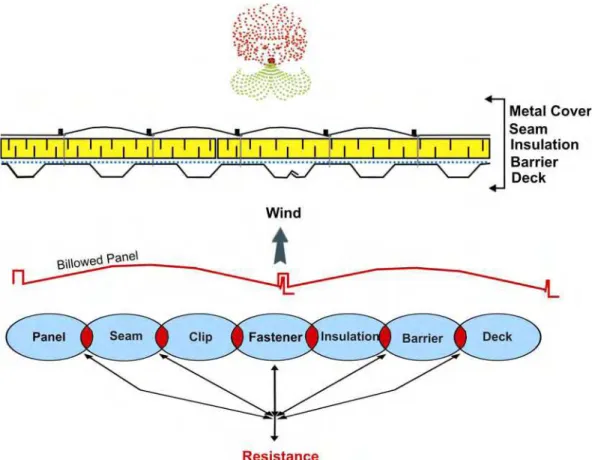
Wind loading on roofs remains to be a complex phenomenon and one of most common factor in roofs failure. This is mainly due to the fact that wind-flow conditions around buildings and wind-induced effects on such buildings have dynamic characteristics that are time and space related. From a space perspective, the wind’s characteristics are affected by aspects such as building geometry, site topography, and architectural features. From a time perspective, the wind dynamic characteristics are affected by wind speed, turbulence intensity and wind direction. It must also be noted that roof is subjected to wind induced negative pressures on the exterior and positive pressures acting on the underside as shown in Figure1.
Figure 1: Wind Induced Pressures on Roofing Assembly
Wind Effects on Composite Assembly
Within the roof assembly, each component of that assembly offers a certain resistance to the wind uplift forces. Figure 2, provides an illustration of the force-resistance link concept. For a roof to resist adequately the wind-uplift forces, all resistance links should remain connected. Failure is considered to have occurred when the wind-uplift force is greater than the resistance of anyone or more of these links. To identify the weakest link, designers need wind-uplift test protocols that mimic the wind load characteristics as well as the types of roof failure modes resulting from such winds.
Figure 2: Weakest Link Illustration for Composite Assembly
Static Vs Dynamic and Panel vs Assembly
On the North American scene, mainly two main test procedures have been in use for determining the wind-uplift resistance of metal roofs:
1. Conventional ASTM E1592-01 “Structural Performance of Sheet Metal Roof and Siding Systems by Uniform Static Air Pressure Difference.”
2. Recent CSA A 123.21 “Standard Test Method for the Dynamic Wind Uplift Resistance of Mechanically Attached Membrane-Roofing Systems.”
CSA A 123.21 represents the only North American test procedure for assessing the wind load uplift resistance under dynamic wind load conditions. The development of this test procedure was the result of the works undertaken by the Special Interest Group for Dynamic Evaluation of Roofing Systems (SIGDERS), a consortium of manufacturers building owners, trade associations and researchers. (www.sigders.ca)
E1592 static testing is inadequate from the standpoint of true representation of wind action, particularly in a storm. A proper simulation of the wind, which is a main characteristic of the CSA A 123.21 is necessary for developing an appropriate presentation of its dynamic features, through rationalized dynamic load cycles that were developed through wind tunnel testing of full-scale roof assemblies. This resulted in qualifying and quantifying the effects induced by wind.
One of the major limitations of the ASTM E1592 lies in the fact that it is limited only to the assessment of the strength of metal panel and its fastening techniques. While, one of the major characteristics of the CSA A 123.21 lies in the fact that the testing is not limited to the covering material itself or to sections of main roofs, rather, it considers the effects on the whole roof assembly, along with its components and the interaction among them (structural elements, retarders/barriers, deck fastening, insulation fasteners and roof covering).
MBMA project on Composite Assembly
A joint research project is on going between National Research Council of Canada (NRC/IRC) and Metal Building Manufactures Association (MBMA), American Iron and steel Institute (AISI) and Copper development Association (CDA) with the main objective of evaluating the performance of composite roof assemblies with metal covering. The project’s hypothesis is to develop the load sharing relationship among the roofing components by quantifying the Pressure Equalization Process (PEP) in the assembly. PEP depends on the air permeability of the various components as well as the field construction details. Therefore, assembly (rather than material) evaluations is accomplished.
This project investigated twelve different assemblies in three different groups as follows: Group 1: Composite assemblies with plywood deck
Group 2: Composite assemblies with steel deck Group 3: Composite assemblies with retarders
Experimental Setup and Test Protocol
Investigations were carried out at the Dynamic Roofing Facility (DRF) of the National Research Council of Canada. Figure 3 shows a typical composite assembly layout and installation at the DRF. The DRF consists of a bottom frame of adjustable height upon which roof specimens are installed and a movable top chamber. The bottom frame and top chamber are 6100 mm (240 in.) long, 2200 mm (86 in.) wide and 800 mm (32 in.) in height. The top chamber is equipped with six windows for viewing, and with a gust simulator, which consist of a flap valve connected to a stepping motor through a timing belt arrangement. All assemblies were subjected to CSA A 123.21-04 dynamic test protocol.
Figure 3: Composite Assembly Layout and Installation at the DRF
Performance of Composite Assemblies Under Dynamic Loading
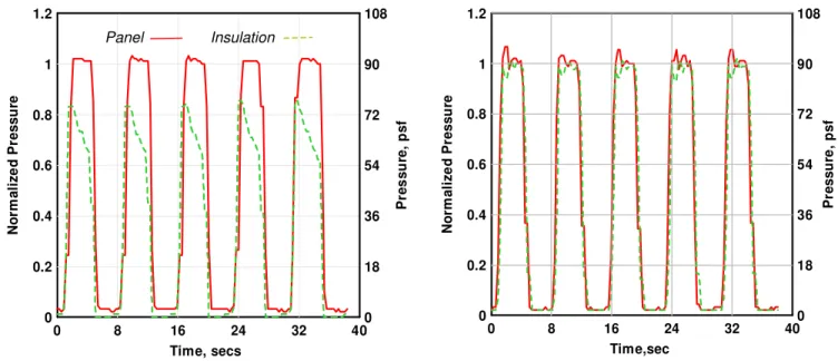
When the assembly is subjected to suction at the top, the panel deforms and transfers the forces through the fastener to the structural deck. Figure 4 shows a typical wind uplift performance of composite assemblies. It has two data sets, one representing a composite assembly without air retarder and the other with retarder. For each set, about five wind gusts are presented at a pressure level of 4.3 kPa (90 psf) and each having duration of about 8 seconds. Within the 8-second period, the panel experiences the maximum pressure of 4.3 kPa (90 psf) for 2 seconds and there is no loading for a period of 2 seconds. Such time varying gust simulation creates fatigue on the assembly. What is interesting is the ratio of sharing of the applied suction between panel and insulation. In the case of assembly with no retarder, the panels resist the applied wind uplift where as the pressure difference across the insulation is only instantaneous. While in assembly with retarder, the insulation boards share about 90% of the applied suction due to the airflow resistance. This mechanism of pressure sharing between the components is indicative of the composite behavior of the assembly and its effect will be reflected in deflection and clip load of the metal panel. This insulation contribution partly reduces the stress on the panel clip-fasteners and facilitates to increase the wind uplift rating of assemblies. To reinforce this observation, measured fastener forces are analyzed and discussed below.
Figure 4: Performance of Composite Assembly under Dynamic Wind Conditions
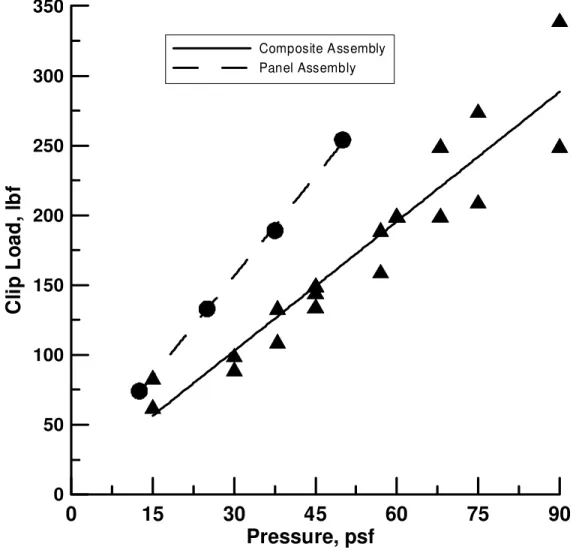
During the wind test, panel clip fasteners were instrumented with load measuring sensors. Figure 5 shows the measured loads at various pressure levels. Data from different assemblies are grouped into two segments; one segment to represent the panel assembly and second to represent the composite assembly. It is clear that the clip loads are reduced in the case of composite assemblies. This is due to the fact that in composite assemblies, as discussed before, the load sharing mechanism of the insulation contributes to lower clip-load of the metal panel. The percentage of load shared by the insulation varies depending on the insulation thickness and the presence of the barrier above the deck.
Figure 5: Reduction in Clip Load at Various Wind Suctions
Failure Modes of Composite Assemblies Under Dynamic Loading
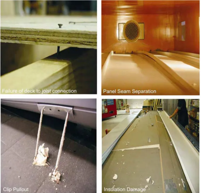
Failure modes of the assemblies were also investigated after the wind test. Typically, three different failure modes were observed. Assemblies from Group 1 with wood deck configuration failed because the net load on the deck exceeded the strength of the deck-to-joist connection. In other words, the fastener attachment of the deck pulled out from the deck-to-joist. In the case of Group 2, panel seams opened or separated during wind testing. The weakest link of this group is the seam-locking mechanism of the metal panels. For the Group 3 configurations with barriers, mostly, clip attachment fasteners pulled out and caused the cracking of the insulation. This preliminary failure triggered the panel seam opening as a secondary failure. In addition deck pullout from the structural joist was also observed in one assembly.
Figure 6: Failure Modes Under Dynamic Loading
Conclusion
Wind-uplift performances of composite assemblies are different from the performance of just panel behavior under static loading. In other words, it is clear that the CSA A 123.21 dynamic test offers advantages over the conventional ASTM E1592. Observation of this on going investigations can be summarized as follows:
In non-composite assemblies, only metal panel resist the simulated wind uplift. For the same pressure level, panel deflection of a non-composite assembly is twice compared to a composite assembly. This excessive panel deformation causes the panel bucking at the middle span between panel clips leading to a failure mode of panel cracking around the clips.
Wind uplift resistance of composite assemblies are better than panel wind-uplift rating. Inclusion of air retarder in a composite assembly, significantly improves the wind-uplift rating.
Load sharing by other components (deck, insulation) is evident in assemblies with air retarder.
ACKNOWLEDGMENT
Authors appreciate the contribution of Mark Henry of Butler Metal Buildings for his assistance in material contribution and assembly installation and Steven Ko, Technical Officer at NRC for running some of these tests. Technical discussions with Lee Shoemaker of MBMA are appreciated.
Figure 1: Wind Induced Pressures on Roofing Assembly
Figure 3: Composite Assembly Layout and Installation at the DRF
0 8 16 24 32 40 Time,sec 0 0.2 0.4 0.6 0.8 1 1.2 N o rm al iz e d P ressu re 0 18 36 54 72 90 108 P ressu re , p s f 0 8 16 24 32 40 Time, secs 0 0.2 0.4 0.6 0.8 1 1.2 No rm a li z e d P res su re 0 18 36 54 72 90 108 Pr e s s u re , p s f Panel Insulation
Composite Assembly without Retarder Composite Assembly with Retarder
0
15
30
45
60
75
9
Pressure, psf
0
0 50 100 150 200 250 300 350Cl
ip
L
o
a
d,
l
b
f
Composite Assembly Panel AssemblyFigure 5: Reduction in Clip Load at Various Wind Suctions