READ THESE TERMS AND CONDITIONS CAREFULLY BEFORE USING THIS WEBSITE. https://nrc-publications.canada.ca/eng/copyright
Vous avez des questions? Nous pouvons vous aider. Pour communiquer directement avec un auteur, consultez la première page de la revue dans laquelle son article a été publié afin de trouver ses coordonnées. Si vous n’arrivez pas à les repérer, communiquez avec nous à [email protected].
Questions? Contact the NRC Publications Archive team at
[email protected]. If you wish to email the authors directly, please see the first page of the publication for their contact information.
NRC Publications Archive
Archives des publications du CNRC
This publication could be one of several versions: author’s original, accepted manuscript or the publisher’s version. / La version de cette publication peut être l’une des suivantes : la version prépublication de l’auteur, la version acceptée du manuscrit ou la version de l’éditeur.
Access and use of this website and the material on it are subject to the Terms and Conditions set forth at
PVC roofing membranes : factors affecting tensile tests
Dutt, O.; Ashton, H. E.
https://publications-cnrc.canada.ca/fra/droits
L’accès à ce site Web et l’utilisation de son contenu sont assujettis aux conditions présentées dans le site LISEZ CES CONDITIONS ATTENTIVEMENT AVANT D’UTILISER CE SITE WEB.
NRC Publications Record / Notice d'Archives des publications de CNRC:
https://nrc-publications.canada.ca/eng/view/object/?id=7ef1fa8e-cc52-46dd-b49e-febe3d87ba2c https://publications-cnrc.canada.ca/fra/voir/objet/?id=7ef1fa8e-cc52-46dd-b49e-febe3d87ba2cSer
THJ.N21d
1National Research
Conseil national
1366
19
Council Canada
de
recherche.
Canada
c. 2
Institute for
lnstitut de
Research in
recherche en
Construction
construction
PVC Roofing Membranes
-
Factors Affecting Tensile Tests
by
0.
Dutt and H.E. Ashton
A N A L Y Z E D
Appeared in
Proceedings of Second l nternational Symposium
on Roofing
Technotogy,
"A Decade of Change and Future
Trends
in
Roofing"
Gaithersburg, MD, September 1 8
-
20 1985
p.
161 -167(IRC Paper No. 1366)
Reprinted with the permission of the
National Roofing Contractors Association
Price
$2.00
NRCC
25850
Bon nombre d'exigences standard relatives
a
l'bvaluation des
membranes de couverture portent sur les essais de traction, qui
s'effectuent
Bl'aide de diverses dthodes.
Dans le cadre de
cette 6tude, on a examing, pour trois types de membranes en
PVC, quelques paramstres influant sur les rgsultats-
des essais
de traction, colmne la tempgrature, la vitesse de chargement, la
longueur de la jauge et la variation des di5formations dans un
Schantillon.
Plus de deux cents Bchantillons ont dtB soumis
aux essais de traction. Les rdsultats indiquent que certaines
des mgthodes utilisges pour l'bvaluation des membranes de
couverture doivent &re soigneusement choisies en fonction du
matgriau
3 l'essai.
PVC
ROOFING MEMBRANES-FACTORS
AFFECTING TENSILE TESTS
0 . M. DUTT
and H.E.
ASHTON
National Research Council of Canada
Ottawa, Canada
SUMMARY
Many standard requirements for the evaluation of roofing membranes involve tensile testing and various methods are specified or have been used for these tests. In this study, some test parameters, such as temperature, speed of loading, gauge length and strain variation within a specimen, that affect the tensile test results, were examined for three types of PVC membrane. Over two hundred specimens were subjected to tensile tests. The results show that some of the test methods used for evaluating roofing membranes need to be carefully selected in relation to the material under test.
A
roofing membrane is subjected to various stresses dur-ing manufacture, application and performance in service. The stresses related to the manufacturing and application generally are predictable and controllable. Those that occur in service are quite complex and extend over a long period of time. They are caused by many factors, such as heat, cold, wind, rain, snow, ice, moisture, occupancy loads, and struc- tural movements, that prevail at different times'in various combinations and unpredictable cycles.'
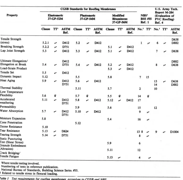
The various forms of loads in the roof-service environ- ment are related to chemical, physical and/or mechanical action, which cause tension, compression, bending, shear, peel, fatigue, etc.' Of all the stresses that cause damage, ten- sile stress occurs most frequently in practice. Consequently, tensile tests are widely used to evaluate roofing materials. In the Canadian General Standards Board standard for plastic sheet roofing,' seven out of twelve physical and mechanical requirements are related to the tensile stress-strain behav- ior of the material. This also is recognized in other stan-
dards and publications, as shown in Table 1
.'.'
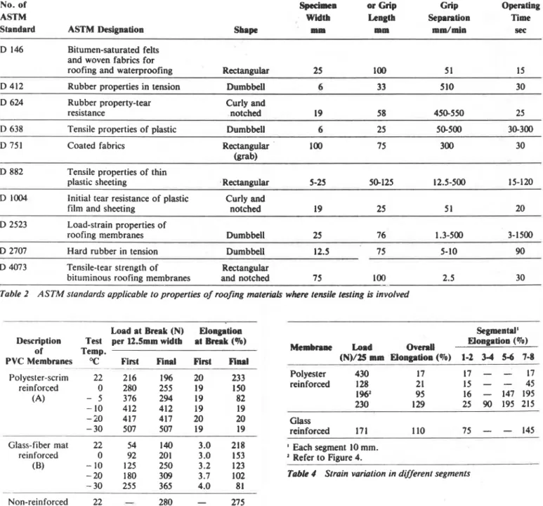
Because membranes vary in chemical and material com- position, different test methods are prescribed in various standards, which specify different specimen shapes, sizes, grip lengths and loading speeds. Some of these "standard" test methods, frequently referred to in testing roofing mem- branes or similar materials, are presented in Table 2. There
is considerable variation among them. A review of these
tests indicates that the differences among the methods may not have a rational basis. It is common to find a test developed for one type of material applied to a completely different type apparently without realization that the test may not be appropriate.' An example in the field of roofing is use of the very high extension rate from the test developed for rubbers (ASTM Method D 412) in evaluating much less elastic materials, such as bituminous roofing materiak6
The effect of some tensile test factors, such as tempera- ture, speed of loading and gauge length, and the strain variation within a specimen, on the results of tests with roof- ing membranes was examined using three types of polyvinyl chloride (PVC) membranes to determine if certain condi- tions are more relevant for roofing materials. This part of the study is concerned with how tensile tests should be per- formed. The different responses of the three materials to the tensile tests after accelerated weathering and fatigue cycling and their relevance to field performance will be presented in a future publication.
TEST CONSIDERATIONS
The study was designed to determine the response of PVC roofing membranes when subjected to tensile testing under various test conditions. The samples represented the three basic types: PVC sheets with polyester fabric reinforcement, with integral non-woven glass fiber mat carrier and without
any reinforcing materials. The three types were labelled A. B
and C, respectively. Values of their strength, elongation and
other parameters were obtained to relate them to the tests. In general, dumbbell-shaped specimens were cut with die A of ASTM Method D 412, which has a width of 12mm, in- stead of the recommended die C3 with a width of 6mm as given in Table 2. For specimens of different dimensions, the test values were adjusted to take into account the differences in width where results were compared.
TESTING AND RESULTS Tensile Tests at Low Temperatures
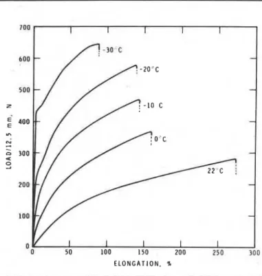
For this test, 45 specimens of PVC membranes were cut using die A of Method D 412. They were subjected to the tensile test on an Instron test machine (model 1122) at 22C and at 0, -10, -20, and -30C in an environmental box. Gauge length of each specimen was 60mm and the crosshead speed was constant at lOmm per minute. Typical load-elongation curves for polyester-scrim reinforced membrane (A) are shown in Figure la, glass-mat reinforced membrane in Figure lb, and non-reinforced membrane (C) in Figure Ic. Mean values of the test results are given in Table 3.
The curves in Figure l a and the results from Table 3 in- dicate that when the temperature decreases, the load at
break increases, while the overall elongation at break
decreases. This behavior could normally be predicted for a PVC sheet because of greater intermolecular friction at cold
temperatures, but the results show a marked difference be-
tween the three types. Comparing their values at room
temperature and at -30C, membrane A shows a loss in
elongation from about 230 to 20 percent, whereas the brcak-
ment and matrix occurs simultaneously at -30C and also at -10 and -20C. With membrane B, the glass mat breaks at low load and negligible elongation but the resin continues to extend after the reinforcement breaks. The resin decreases in elongation from about 220 to 80 percent, while the ultimate load increases to about 2% times the original value. For the non-reinforced membrane, the changes in load-elongation values are similar to those of material B after the fracture of glass fibres.
Tensile tests conducted at low temperatures provide more information on the tension failure of the material than the low temperature bend test (Table 1). In the bend test a specimen, cooled to -30C and bent over a specified cur- vature, is visually inspected for any tension cracks. This test depends solely on visual inspection, which could miss microcracks on the membrane surface. The tensile test gives quantitative information of the stress, which can be related to the tension cracks due to bending using principles of flex- ural mechanics. Because there are significant variations in the load-elongation properties of different membranes at cold temperatures, tensile testing at cold temperatures should be considered an essential method in evaluating
PVC,
as well as other roofing membranes intended for use in cold climates.Speed of Loading
In various standards, the speed of loading, or grip scpara- tion, varies from 1.3 to 550mm per minute (Table 2). For PVC membranes, it is 500mm per minute. To study the in- nuence of [his factor on behavior during tensile testing, twenty-four specimens cut with die A of ASTM
D
412 from each of the three types of membrane were tested at cross- head speeds of 2, 5, 10, 20, 50, 100, 200 and 500mm per minute.The effect of speed of loading on the resulting load at break of the specimens can be seen in Figure 2. At low speeds there is a steep rise in the values of breaking loads, but at speeds beyond 1OOmrn per minute, strength is not very dependent on the rate of loading for a given type of PVC. It indicates that the SOOmm per minute speed is not necessary
to obtain a reasonably accurate value of the maximum strength in tension. A lower speed is adequdie and is closer to the conditions imposed in the field by variable weather conditions. Also, lower speed is convenient I .r making meaningful observations during the test. Thus, a loading speed of not more than lOmm per minute is recommended for evaluating
PVC
membranes at room temperature.Gauge Length Variation
Gauge length is another aspect that may influence the resuIt of tensile tests of materials, particularly when the test specimens are rectangular and the initial spacing of jaws is considered the gauge length. Jaw slippage, deformation due
to jaw pressure and higher strain at the neck of the specimen contribute to the error. In order to study this factor, dif- ferent roofing materials, non-reinforced
PVC
membrane, asphalt felt and asphalt shingle, were included in the experi-ment. Because reinforced membranes suffer excessively high strains where necking occurs, they are discussed under strain variation.
Five sets of 24 specimens each were obtained from the samples, with specimens cut to gauge lengths of 5, 10, 20, 50, 100 and 200mm. The
PVC
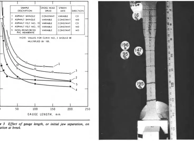
specimens were specially cut with dumbbell ends, so that they provided wider ends forproper gripping, but only the straight section extended out of the jaws. The felt and shingle specimens were 25mm wide rectangular strips. They did not need wider grip ends because of the materials' low ultimate strength. Each set was cut along the machine direction or cross-machine direction and was tested either at a constant crosshead speed or at a constant rate of strain, using the separation of grips as a measure of elongation. The results and test conditions are shown in Figure 3.
From the curves in Figure 3, it is evident that the recorded elongation of shorter specimens is significantly greater than the true value because of the relatively greater contribution of the neck and end effects. A small change in the gauge length of less than 50mm causzs a large change in elonga- tion. With increasing lengths, the effect of these factors becomes less significant and is relatively negligible above l00mm gauge length. However, from the point of view of the time required to perform the test and the size of specimens of highly elastic material which requires long travel of the machine cross-head, a gauge length of 50 to 70mm should be acceptable. Specimens cut with Die A of ASTM D 412 fall within this range. For membranes with widely spaced reinforcing mesh, a wider specimen contain- ing a representative number of strands is required for repeatability of results. For this purpose, the 25mm wide die of ASTM Standard D 2523 could be considered. Any specimen found to be short of a representative number of reinforcing strands is discarded.
In the case of dumbbell-shaped specimens subjected to tensile tests, elongation of gauge length commonly is measured by hand held scales, due to the lack of a simple and accurate extensometer for highly stretchable materials. In the test the ungripped portion of dumbbell ends, having variable width, elongates differently from the straight por- tion, where gauge length has been defined between bench marks. In order to compute the elongation of gauge length from the total elongation, a mathematical model can be developed for numerical integration of the elongation of end portions, taking into account their varying widths and the non-linear stress-strain property of the material. This model is applicable only to non-reinforced membranes, as the deformation of other types is governed by the reinforce- ment.
Strain Variation
In this test, 15 dumbbell-shaped specimens, each 25mm wide, were s~ecially cut from the three
PVC
membrane samples and tested at a loading speed of lOmm per minute. In order to study, separately and together, the behavior in tension of the two components, reinforcement and matrix, of the reinforced PVC membrane, a test was designed inwhich
a steel tape was attached to the jaws alongside the specimen being pulled. The assembly was photographed atintervals and the load-extension chart was marked the ins- tant each photograph was taken. The elongations were measured from the prints (Figure 4), and are reported in Table 4. The non-reinforced
PVC
specimens showed only small strain variation, and are not included in the table.The percent elongations in various segments of the specimen are not equal. Once the reinforcement breaks, the elongation in the now unreinforced segment becomes much greater than in the remaining reinforced portion. This condi- tion gives a 129 percent average value of elongation of the
material over the gauge length rather than the true elonga- tion of 215 percent (Table 4) at the site of potential break. This effect is significant with reinforced membranes only. It implies that a n elongation requirement in specifications for the reinforced type, has a factor of safety incorporated in it. This is seen in the example cited above, which has a factor of safety of 1.67 over the average elongation for the matrix.
CONCLUSIONS
The present study looks a t the methods of tensile testing the three basic types of PVC roofing and waterproofing mem- branes. From the results of these tests, it is concluded that: 1 . Tensile tests a t low temperature give significant informa- tion about the variability of the load-elongation proper- ties between materials at different temperatures. O n e material's elongation changed from about 230 percent a t room temperature to 20 percent at -30C. This informa- tion can supplement the cold bend test, which is based o n visual observation.
2. Load at break of a membrane is influenced by loading speed. It becomes essentially independent of load speeds beyond lOOmm per minute. It therefore is necessary that the strength of a membrane be defined in relation t o the speed of loading. A rate of grip separation in that vicinity should be adopted in place of the existing 500mm per minute.'
3. Elongation at break of specimens where jaw separation is used for gauge length is significantly affected by slippage and deformation of specimen at the jaw as well a s the neck formation in the vicinity of the fracture. Its relative significance decreases with increasing gauge length and bccomcs negligible for lengths greater than 100mm. 4. In a reinforced membrane, reinforcement breakage
ceuses localized strain which is higher than the strain over the gauge length. This must be taken into consideration when specifying strain requirements of such membranes.
ACKNOWLEDGEMENTS
The authors wish to express their thanks to G.A. O'Doherty for his assistance in the experimental work. This paper is a contribution of the Division of Building Research, National Research Council of Canada. and is published with the approval of the Director.
REFERENCES
'
Mathey. R.G.. and Cullen, W.C., Preliminary Performance Criteria for Bituminous Membrane Roofing, U.S National Bureau of Standards, Building Science Series Publication No. BSS 55. November 1974. pp. 2-9.Mathey, R.G., and Rossiter. W.J.. Single Ply: Evaluating Tensile and Elongation, 1982 Handbook of single-ply roofing systems. published by RSI Magazine. New York. pp. 52-54.
'
Canadian General Standards Board (CGSB) 37-GP-54M, Stan- dard for Roofing and Waterproofing Membrane. Sheet AppBed, Flexible. Polyvinyl Chloride. CGSB, Hull. Quebec, January 1979. pp. 2-5.' Rosenfield, M.J.. An Evaluation of Polyvinyl Chloride (PVC) Single-Ply Roofing Systems, Technical Report M-284. U.S. Army Corps of Engineers. Construction Engineering Research Laboratory. Champaign, Illinois, March 1981. pp. 9-1 1.
'
Ashton, H.E.. Evaluating the Performance of Organic Coatings and Building Materials. Symposium on Permanence of Organic Coatings, January 1981. ASTM STP 781, August 1982, pp. 67-85.CGSB 37-GP-56M, Standard for Membrane, Modified, Bituminous. Prefabricated and Reinforced for Roofing, CGSB, Hull, Quebec. July 1980, pp. 2-7.
The information presented indicates the importance of factors affecting tensile tests o n PVC membranes. The observations show that careful consideration must be used when defining test methods and procedures for evaluating material behavior.
CGSB Strad.rds for Roofing Membranes U.S. Army Tech. Reporl M-284 PropcW Elaslomerie P k s t o w t i c Modified NBS' (Evaluation of 37-GP-52M 37-GP-54M B i t ~ ~ m i ~ o l ~ ,
Bss
#SS PVC Roofing)376P-56M m.1 R e f . 4
Clause TI" ASlM Chuse
'IT1
ASTM Cbwe TI'' ASTM No.' TT' No.' 'IT' ASTMRef. Ref. Ref. Ref.
Tensile Strength D638
(stress) 5.2.1 rr W 1 2 5.2 v W 1 2 1 v 6 rr D882
Breaking Strength 5.2.2 rr D751 5.1 rr W 1 2
Lap Joint Strength 5.3 rr W 1 2 5.3 H W 1 2 5.1 rr W 1 2 7 D638
Ultimate Elongation/ D412 D882 Elongation at Break 5.4 rr D751 5.4 .C D412 5.2 rr W 1 2 8 rr D638 Load-Strain Product 5.3 rr W 1 2 Tensile Set 5.5 rr W 1 2 Dynamic Impact 5.12 5.5 5.8 7 15 Heat Aging 5.9 rr W 1 2 5.6 rr D412 13 rr D638 D75 1 14 D882 Thermal Stability 5.11 5.7 2 10 Low Temperature Flexibility 5.6 U 5.7 U 5.5 U 14 U Accelerated 5.11 rr W 1 2 5.8 rr W 1 2 5.12 rr D412 17 weathering D751 Permeability 5.9 5.6 15 12 Water Absorption 5.7 rr W 1 2 5.10 rr D412 9 rr D75 1 Moisture Expansion 5.8 5.4 16 f l Cone Penetration 5.12 Ozone Resistance 5.10 Tear Resistance 5.13 rr D624 13 8 rr 9 Dl004 Tearing Strength 5.14 rr Dl51 8 rr Static Puncturing
Test (Shear Stress) 5.9 6
Granule Embedment
(Abrasion) 5.11 12
Crack Bridging/
Tensile Fatigue 5.13 rr 4 rr I
'
Where tensile testing involved.Numbering of tests in reference publication.
'
National Bureau of Standards, Building Science Series #55. U Related to tensile stress in flexural loading.Table I Test requirements for r w n g membranes accordtng to CGSB and NBS.
Gauge Rate of Approx.
No. of Specimen or Grip Grip Operating
ASTM Width Length Separation Time
Standard ASTM Designation Shape nun mm mm/min see
D 146 Bitumen-saturated felts and woven fabrics for
roofing and waterproofing Rectangular 25 100 5 1 I5
D 412 Rubber properties in tension Dumbbell 6 33 510 30
D 624 Rubber property-tear resistance
Curly and
notched 19 58 450-550 25
D 638 Tensile properties of plastic Dumbbell 6 25 50-500 30-300
D 751 Coated fabrics Rectangular 100 75 300 30
(grab) D 882 Tensile properties of thin
plastic sheeting Rectangular
-- -
D 1004 Initial tear resistance of plastic Curly and
film and sheeting notched 19 25 5 1 20
D 2523 Load-strain properties of
roofing membranes Dumbbell 25 76 1.3-500 3-1500
D 2707 Hard rubber in tension Dumbbell 12.5 75 5-10 90
D 4073 Tensile-tear strength of Rectangular
bituminous roofing membranes and notched 75 100 2.5 30
Table 2 ASTM standards applicable to properties of roofing materials where tensile testing is involved
Load at Break (N) Elongation Segmental'
Description Test per 12.5mm width at ~ r & k (%) Elongation (To)
of Temp. Membram Load Overall
PVC Membranes OC First Find First Flml (N)/25 . - mm Elongation .- (%) 1-2 3-4 5-6 7-8
- Polyesler-scrim 22 216 1% 20 233 reinforced 0 280 255 19 I 50 (A) - 5 376 294 19 82 -10 412 412 19 19 -20 417 417 20 20 -30 507 507 19 19 Glass-fiber mat 22 54 140 3.0 218 reinforced 0 92 201 3.0 153 (B) -10 125 250 3.2 123 - 20 180 309 3.7 102 - -30 255 365 4.0 81 Non-reinforced 22
-
280-
275 ( C ) 0-
353-
147 -10-
471-
145 -20-
572-
138 -30-
638-
83Table 3 Load and elongation at break for PVC membranes at different temperatures (fist value is when reinforcement breaks).
Polyester 430 17 17
-
-
17 reinforced 128 21 I5- -
45 1 96' 95 16-
147 195 230 129 25 90 195 215 Glass reinforced 171 110 75-
-
145 I Each segment 10 mm. Refer to Figure 4.I I I I I
I
50 100 150 200 250 100E L O N G A T I O N , %
--
Figure l a Load-elongation curves for polyester-scrim reiqforced PVC membrane at different temperatures. First peak--r.~iMorce- ment breaks, second peak-total section breaks. A t -10, -20 and
-30C both break simultaneously.
1 I I 1 I
I
0 SO 100 150 200 250 300
E L O N G A T I O N , %
Figure I b Load-elongation curves for glass-mot reiMorced PVC
membrane at different tempemtures. First peak-reiMorcement breaks, second peak-total break.
-
-
-
-
-
-
300 E L O N G A T I O N , %Figure l c Loud-elongation curves for non-reiMorced PVC mem-
brane at different temperatures
5 0 1 I I 1 I
I
0 100 200 30 0 400 500
L O A D I N G S P E E D . m m l m i n
Figurn 2 4 f e r t of loading speed on laxi at break for PVC mem-
100 150
G A U G E L E N G T H . m m
r r
SAMPLE CROSS HEAD STRAIN
DESCRIPTION SPEED dATE DIRECTION
a I ASPHALT SHINGLE CONSTANT VARIABLE C D
2 ASPHALT SHINGLE VARIABLE CONSTANT M D
-
3 ASPHALT FELT N O . 15 VARIABLE CONSTANT C D4 ASPHALT FELT N O . I 5 VARIABLE CONSTANT M D
5 NON-REINFORCED VARIABLE CONSTANT MD
PVC MEMBRANE
-
NOTE VALUES FOR CURVE N O . 5 SHOULD BEMULTIPLIED BY 100 -
-
'4-
I I I I Figure 3 Effect of elongation at breokgauge length, or initial jaw separation,
Figure 4 Example of strain variation in different segments of poly- ester-scrim reinforced PVC membrane. Refer to line 3 in Table 4.