Publisher’s version / Version de l'éditeur:
Vous avez des questions? Nous pouvons vous aider. Pour communiquer directement avec un auteur, consultez la
première page de la revue dans laquelle son article a été publié afin de trouver ses coordonnées. Si vous n’arrivez pas à les repérer, communiquez avec nous à [email protected].
Questions? Contact the NRC Publications Archive team at
[email protected]. If you wish to email the authors directly, please see the first page of the publication for their contact information.
https://publications-cnrc.canada.ca/fra/droits
L’accès à ce site Web et l’utilisation de son contenu sont assujettis aux conditions présentées dans le site
LISEZ CES CONDITIONS ATTENTIVEMENT AVANT D’UTILISER CE SITE WEB.
Research Paper (National Research Council of Canada. Division of Building
Research); no. DBR-RP-644, 1975-02
READ THESE TERMS AND CONDITIONS CAREFULLY BEFORE USING THIS WEBSITE.
https://nrc-publications.canada.ca/eng/copyright
NRC Publications Archive Record / Notice des Archives des publications du CNRC :
https://nrc-publications.canada.ca/eng/view/object/?id=a52f503c-7a63-4b06-b00d-4d0d6add677c https://publications-cnrc.canada.ca/fra/voir/objet/?id=a52f503c-7a63-4b06-b00d-4d0d6add677c
NRC Publications Archive
Archives des publications du CNRC
This publication could be one of several versions: author’s original, accepted manuscript or the publisher’s version. / La version de cette publication peut être l’une des suivantes : la version prépublication de l’auteur, la version acceptée du manuscrit ou la version de l’éditeur.
For the publisher’s version, please access the DOI link below./ Pour consulter la version de l’éditeur, utilisez le lien DOI ci-dessous.
https://doi.org/10.4224/40001758
Access and use of this website and the material on it are subject to the Terms and Conditions set forth at
Simple analysis of smoke-flow problems in high buildings
McGuire, J. H.; Tamura, G. T.
Ser TH1
I N21r2
~ M A L Y Z E D
no*
644
NATIONAL RESEARCH COUNCIL OF CANADA c. 2
CONSEIL NATIONAL D E RECHERCHES D U CANADA
BLDG
Simple Analysis
of
Smoke-Flow
Problems in High Buildings
byJ.
H. McGuire and G. T. TamuraReprinted from F I R E TECHNOLOGY Vol. 11, No. 1, February 1975
p. 15-22
Research Paper No. 644 of the
Division of Building Research
SOMMAIRE
On prQsente une expression du mouvement vertical maximal dans un puits simple par suite de l'appel d'air, avec extension
B
un Gdifice simple e t 21 1'6valuation du flux d'air requis pour pressuriser un Qdifice. Le principal avantage de cette expres- sion et d'expressions dGrivGes est d'offrir une- -
meilleure con-n a i s ~ " d e dQ B
Yap. -tionnels
I
REPRINTED FROMFIRE TECHNOLOGY
I
Vol. 1 1 No. 1 February 1975Simple Analysis
of
Smoke-Flow
Problems
in
High Buildings
J. H.
McGUIRE and G. T. TAMURADivision of Building Research
National Research Council of Canada
An expression is given for the maximum vertical flow in a simple shaft as a result of stack action. It is intended t o relate to a simple building and t o the evaluation of the airflow necessary t o pressurize a building.
A
S VIEWED by the Division of Building Research, National Research Council of Canada, the most important mechanism of smoke move- ment (apart from air-handling systems) to be combated in high buildings in Canada1. is stack effect associated with building heating. Whether discussing smoke movement in an unprotected building or the develop- ment of smoke control measures, the flow patterns found in buildings are often so complex that a detailed analysis of all the features, on which quantitative information is desirable, usually necessitates a computer study.This situation has created the widespread impression that no quantita- tive analysis of techniques of controlling smoke in high buildings is pos- sible without the aid of a computer or at least without the aid of results derived from a computer. A corollary of this impression is that under- standing of the influence of various parameters on smoke flow patterns is limited.
The object of this presentation is t o show that a number of interesting building air flow patterns can, to a close approximation, be completely analyzed, both quantitatively and qualitatively, with the aid of ele- mentary mathematics. The derivation of the appropriate expressions has the valuable side effect that it gives a clearer overall picture of the problem and of the influence of various parameters on flow patterns.
F L O W I N A L E A K Y S H A F T
The building component worth studying first, in relation to the smoke problem in high buildings, is a vertical shaft, and it will be considered as illustrated in Figure 1, completely divorced from a building. The figure
15 Copyright 1975. NATIONAL FIRE PROTECTION ASSOCIATION, 470 ATLANTIC AVE., BOSTON, MASS. 02210
Printed in U.S.A.
Fire Technology
I
I 4 I N T E R I O R TEMPERATURE;&
'
1 I N T E R I O R A I R D E N S I T Y p I - - - f - - + I A h - - - iA +- -L E A K Y W A -L -L ( -L E A K A G E & A R E A " a " PER U N I T H E I G H T )"+
-5 I N E U T R A L P R E S S U R E P L A N E E X T E R I O R T E M P E R A T U R E - E X T E R I O R A I R D E N S I T Y - p,Figure 1. Analysis of stack action in a shaft.
relates to that portion of the shaft beneath the neutral pressure plane, which is defined as that level a t which the interior pressure equals the exterior pressure. The flow expression to be derived is confined to the usual condition where a real neutral pressure plane is located at some level between the top and bottom of the shaft.
It
will subsequently be shown that development of the theory will actually permit determination of this level where it is not known. On some occasions, where one particularly large opening between interior and exterior exists, it will be obvious t h a t no substantial pressure difference can exist across it and hence that the neutral plane is a t that level (or very close t o it).At some level h beneath the neutral plane, the pressure difference across an element of wall will be given by the difference in weight be- tween the interior and exterior columns of gas and hence will be:
The relationship between density and absolute temperature T permits this to be expressed as:
6p = hgple/T,
where
e
=T I
-To,
i.e., difference between interior and exterior tempera- ture.The gas velocity created by this pressure difference may be derived from Bernoulli's relationship
6p = pv2/2
where v = gas velocity, and p = density of flowing gas.
Rearranging and substituting for 6p:
I n the particular case under discussion p = p,.
Smoke-Flow Analysis 17
where a is leakage area per unit height and 0 is an orifice factor associated with flow patterns a t a n orifice and is usually about 0.6 in the present context. Thus
6F = pa(2hgpl e/Top)112 6h
Integrating over the height H N gives the result that the flow into the shaft
as a result of stack action is:
Where the outflow of gases from a shaft above the neutral plane is considered, precisely the same expression results. In this case however the temperature of the outflowing gases will be TI, so that the value of p to be used in the denominator will be p = pl.
The two forms of the expression may be used together, for example, t o derive the level of the neutral plane in a shaft with uniform leakage, closed a t the bottom and top. Mass flow conservation rules that
P o F ~ ~
= ~ ~ F o z r tfrom which
HT/HB = (T1/To)lI3
where H T = height of top of shaft above neutral plane and H B = height of neutral plane above bottom of shaft.
As HT
+
HB
= the height of the shaft, the location of the neutral plane can be calculated. For example where the interior and exterior temperatures are. 75"F
and 0" F, the neutral plane would be located 48 percent up the height of the shaft rather than halfway, the generally accepted approximation.Where a shaft departs from the complete uniformity of the case con- sidered so far, the preceding treatment can often be extended t o cover it. Thus in the case of a top vented shaft, writing
A
= area of t o p vent, the expression for the total flow out of the portion of the shaft above the neutral plane will becomeEquating mass flows into and out of the shaft with a view to determining the level of the neutral plane gives the equality
This expression is much more cumbersome than the simpler case repre- sented by Equation 2 and hence its value is questionable.
It
reduces to Equation 2 ifA
= 0, and ifA
tends t o S n i t y , it indicates that the neutralplane will be a t the top of the shaft ( H T tends to 0).
A P P L I C A T I O N T O B U I L D I N G S
So far the discussion has been confined to shafts as separate con- structions; whereas it is shafts as components of buildings and flows in
18 Fire Technology
buildings generally that are of interest in resolving smoke problems. Surprisingly enough it will be found that the expressions so far derived are directly applicable, to a reasonable approximation, t o buildings. T h e leakage factor a usually requires modification a s becomes apparent when t h e subject is investigated in detail.
The analysis of certain building flows where the building is approxi- mately represented by a shaft becomes possible because a very large pro- portion of t h e air that enters a t a low level and leaves a t a high level i n a multistory building moves vertically through t h e shafts. Tamura2 demon- strated that, in a hypothetical twenty-story building, with leakage char- acteristics based on measured values, the proportion exceeds 96 percent.
Two factors favor flow via the shafts. Firstly, the aggregate leakage area to shafts greatly exceeds t h a t through floors. I n a typical building, leakage through a floor might be less than 4 square feet whereas leakage area t o the shafts will probably be about 5 square feet per story. T h e aggregate of leakage either into or out of t h e shaft, for a symmetrical building, will thus be this value times half t h e number of stories in t h e building.
The second feature emphasizing the shaft path is t h a t flow from one story t o another via the shaft only involves two openings in series whereas flow from, for example, the first to t h e twentieth floor by way of the floors involves passage through nineteen leakage areas in series.
The simplifying assumption that is adopted as the basis of subsequent analysis in this paper is t h a t floors are airtight. Under these circumstances the building may be represented by a single shaft in which inlet leakage actually comprises two leakages (the exterior wall and shaft leakage) in series. Writing
I a, = exterior wall leakage/unit height, and
a, = shaft wall leakage/unit height
t h e effective value of a will be
A
typical value of the ratio a,/a, is 2, and it is informative t o note that, under these circumstances, a = 0.89 a,. An interesting observationt o be made from this evaluation is that, in a typical building where t h e aggregate of shaft leakage is double the exterior skin leakage, the in- filtration and exfiltration into and out of the building are about 90 per- cent of the values they would assume if there were no interior partitions (walls, floors, etc.) within the building. I n other words, the influence of interior partitions on total infiltration and exfiltration is minimal.
Having represented the building by a n equivalent shaft, a number of features can now be analyzed. One interesting and simple derivation is of t h e steady-state concentration of pollutant in t h e upper half of a building in terms of the concentration on some particular floor. If a fire occurs o n
Smoke-Flo~v Analysis 19
the ground floor and the pollutant concentration there is Co, the ratio
12/15',,
(where C is the steady state pollutant level in the upper half of the building) is obviouslyC - flow into shaft from ground floor
- -
C,, flow in shaft a t neutral plane
The expressions given in the preceding section then give the result
where N = the number of stories in the building.
If the fire floor is divided into n symmetrical compartments, it is im- mediately possible to write
C = 3Co/Nn
(4)
The logic behind this development is that, if only one compartment on the floor is involved in fire, the pollutant flowing into the shafts from it will be diluted with (n
-
1) parts of uncontaminated air issuing from the other compartments.As contaminant levels corresponding to C/Co = 0.01 are generally tolerable, the expression indicates that, where Nn
2
300, smoke problems inthe upper parts of a building as a result of fire on a low level story could be minimal. The validity of the expression depends on the maintenance of symmetry and thus assumes, for example, that windows will not be broken. Nevertheless the expression is interesting in indicating the trends to be expected with variation of N and n.
P R E S S U R I Z A T I O N O F B U I L D I N G S O R S H A F T S A further useful application of Expression 1 is in predicting the air flows required to pressurize a building as part of a smoke control measure. Measure
H
of Supplement No. 33 to the National Building Code of Canada, as amended in 1973, achieves smoke control by total pressuiization in combination with venting of the fire floor. Such a n arrangement ensures that, a t all internal boundaries of the fire compartment, flow is towards the fire, not away from the fire. The level of pressurization required to comply with measureH
is such as to produce coincidence of the interior and exterior pressure characteristics a t grade level, prior to venting.The ideal case, which can be readily analyzed, occurs when the distri- bution of the injected air is such as to produce no pressure differentials across partitions within the building. A single characteristic then describes the conditions in the building as illustrated in Figure 2. I t is to be em- phasized that this characteristic is only of interest in deriving appropriate air flow rates. An essential subsequent measure needed to establish satisfactory smoke control is the venting of the floor space involved in fire. The feature of Figure 2 that permits immediate application of Ex- pression 1 is that the conditions represented correspond precisely t o those
Fire Technology
Figure 2. Idealized char-
- acteristic of a pressurized
building.
v
P R E S S U R E L
above the neutral pressure plane in a shaft. The (heated) air entering the region and leaving through the exterior walls is actually being delivered by air-handling systems, rather than rising from some lower portion of the building, but this factor is irrelevant to the application of the expression. The interior partitions (walls, floors, etc.) are of no importance in the analysis and the exterior walls of the building represent the bounding walls of a portion of a shaft above a neutral pressure plane. I n Expression 1 therefore the value of a relates to the leakage area per unit height of the exterior wall of the building and, as the air leaking out is heated, p = pl.
The total flow is thus
F = ap(8g0/9To)'"W3'" (5) where p = ori£ice coefficient .= 0.6, g = acceleration due to gravity, To =
absolute exterior temperature, 6 = temperature difference between in-
terior and exterior, and H = height of building. Values given by the ex-
pression, of course, agree with Graph 6, relating to building pressurization, in the National Building Code docurnent.3
An important merit of Expression 5 is t h a t it indicates the effect of the different variables involved. As would be expected the air flow re- quirement, F, will depend linearly on a (leakage area/unit height). Tem- perature difference, 0, will have much less effect and the critical factor will be H , (F varies as H3''. The reason for the three halves power law be- comes apparent if the expression is rewritten
F = p(aH) (8gH0/9To)""
where the factor
(aH)
constitutes the leakage of the exterior skin and the last factor is associated with the stack effect giving rise t o the outflow of the heated air.Where ,Imperial Engineering Units are t o be used and the orifice factor is taken as 0.6 Expression 5 becomes
Smoke-Flow Analysis 21 where in this case the units of
F
are specifically cubic feet per minute and those ofH
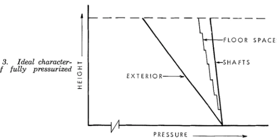
are feet.Another approach t o pressurizing a building is t o inject air into all the shafts, the basic criterion being unchanged: the establishment of co- incidence of the characteristics a t grade level. Figure 3 illustrates the idealized characteristics of a building in which the distribution of (heated) air to the different shafts is such as to produce coincidence of t h e char- acteristics.
Development of the analysis parallels that for the pressurized building, and it is sufficient to report the end result that Expression 5 applies, the value of cr in this case however being a n equivalent value relating to the
leakages of the exterior and shaft walls in series as given by Expression 3. For a typical building, where cr,/crw
-
2, the equivalent leakage, a s statedearlier, is about 90 percent of the value of a, the exterior wall leakage.
The air supply required for this approach will thus be about 90 percent of that required for building pressurization aimed a t achieving a single building characteristic as in Figure 2. As this reduction is not very sub- stantial, it is worth noting, as a n aside, that injection into shafts as a means of implementing the building pressurized concept has a number of merits and avoids certain practical pitfalls t h a t are associated with injection into floor spaces.'
I t would be most helpful if further development could be made to predict the air flows required to pressurize shafts adequately in a building in which some of the shafts are top vented. Under these circumstances flow requirements are sharply reduced. Unfortunately, however, t h e flow pattern produced leads to complication in the establishment of the govern- ing expressions. Their resulting complexity reduces their values and one might as well suggest that a computer be invoked in the basic analysis of this problem. Numerous computer analyses have of course been carried out and thus design data for a combination of top venting and air injection are already a ~ a i l a b l e . ~
Figure 3. Ideal character- + istic of fully pressurized I
shafts. o - W I
- - - -
FLOOR S P A C E S " P R E S S U R E22 Fire Technology
C O N C L U S I O N S
An expression can be readily derived for the maximum vertical flow in a simple leaky shaft as a result of stack action. Some limited develop- ment of this expression to cover nonuniformities is possible but is not likely to prove useful.
I t is shown that, for some applications, a building can be represented as a shaft and hence the expression referred to considered applicable. Air flow requirements for building pressurization as a component of a smoke control measure are discussed and an appropriate form of the same expression presented. I t is shown that injection into shafts is likely to give a 10 percent reduction in the total air requirement.
I t is suggested that analysis of problems involving vented and pressur- ized shafts becomes too complicated to be regarded as a simple extension of the approach developed. A source of data developed with the aid of a computer is referenced.
R E F E R E N C E S
McGuire, J. H., G. T. Tamura and A. G. Wilson. "Factors in controlling smoke in high buildings", ASHRAE Symposium Bulletin "Fire Hazards in Buildings," San Francisco, 19-22 Jan., 1970, pp. 8-13.
ZTamura, G. T., "Computer analysis of smoke movement in tall buildings,"
ASHRAE Transactions Vol. 75, P t 11, 1969, pp. 81-92. DBR Research Paper No.
452. NRCC 11542.
a "Measurements for fire safety in high buildings" (to form part of Supplement
No. 3 t o the National Building Code of Canada), Associate Committee of the National Building Code, Ottawa, 1973, NRCC 13366, pp. 52-56, 95-97.
4 Tamura, G. T., and J. H. McGuire. "The pressurized building method of con-
trolling smoke in high-rise buildings," DBR Technical Paper No. 394. NRCC 13365. Ottawa, Sept. 1973.
This publication is being distributed by the Division of Building Research of the National Research Council of Canada. I t should not be reproduced in whole or in p a r t without permission of the original publisher. The Division would be glad to be of assistance in obtaining such per- mission.
Publications of the Division may be obtained by mailing the appropriate remittance (a Bank, Express, or Post Office Money Order, or a cheque, made payable to the Receiver General of Canada, credit NRC) to the National Research Council of Canada, Ottawa. KIA 0R6. Stamps are not acceptable.
A list of all publications of the Division is available and may be obtained from the Publications Section, Division of Building Research, National Research Council of Canada, Ottawa. KIA 0R6.