Publisher’s version / Version de l'éditeur:
Vous avez des questions? Nous pouvons vous aider. Pour communiquer directement avec un auteur, consultez la première page de la revue dans laquelle son article a été publié afin de trouver ses coordonnées. Si vous n’arrivez pas à les repérer, communiquez avec nous à [email protected].
Questions? Contact the NRC Publications Archive team at
[email protected]. If you wish to email the authors directly, please see the first page of the publication for their contact information.
https://publications-cnrc.canada.ca/fra/droits
L’accès à ce site Web et l’utilisation de son contenu sont assujettis aux conditions présentées dans le site
LISEZ CES CONDITIONS ATTENTIVEMENT AVANT D’UTILISER CE SITE WEB.
Paper (National Research Council of Canada. Institute for Research in
Construction), 1986
READ THESE TERMS AND CONDITIONS CAREFULLY BEFORE USING THIS WEBSITE. https://nrc-publications.canada.ca/eng/copyright
NRC Publications Archive Record / Notice des Archives des publications du CNRC : https://nrc-publications.canada.ca/eng/view/object/?id=2e74c8f3-95de-4a38-9a76-da785c9b17ac https://publications-cnrc.canada.ca/fra/voir/objet/?id=2e74c8f3-95de-4a38-9a76-da785c9b17ac
NRC Publications Archive
Archives des publications du CNRC
This publication could be one of several versions: author’s original, accepted manuscript or the publisher’s version. / La version de cette publication peut être l’une des suivantes : la version prépublication de l’auteur, la version acceptée du manuscrit ou la version de l’éditeur.
For the publisher’s version, please access the DOI link below./ Pour consulter la version de l’éditeur, utilisez le lien DOI ci-dessous.
https://doi.org/10.4224/40001387
Access and use of this website and the material on it are subject to the Terms and Conditions set forth at
Heat transmission in fire test furnaces
Sultan, M. A.; Harmathy, T. Z.; Mehaffey, J. R.
S e r TH1 - -
NZld
no. 14
5 1
1
$,
National Research
ConseiI national
c . 2
Councll Canada
de recherche8 Canada
BLDG
- -
Institute for
lnstitut de
Research in
recherche en
Construction
construction
Heat Transmission
in Fire Test Furnaces
by M.A. Sultan,
T.Z.
Harmathy and J.R. Mehaffey
Reprinted from
Fire and Materials
Vol. 10, No. 2, June 1986
p. 47
-
55
flRC Paper No. 1451)
Price $4.00
NRCC 27636
I
NFPC-
CISTIL I B R A R Y
Ce t t e Q t u d e t h g o r i q u e e t expgr i m e n t a l e , q u i complste c e l l e mentionnge
2
l a r g f g r e n c e 1, p o r t e s u r les f a c t e u r s q u i i n f l u e n t s u r l ' e f f i c a c i t g d e s e s s a i s d e r g s i s t a n c e a u f e u . Le t r a n s f e r t c o n v e c t i f d e c h a l e u r dans l a chambre d ' e s s a i s p e u t e n v e n i r2
f a i r e p a r t i e i n t g g r a l e du p r o c e s s u s d e t r a n s m i s s i o n d e l a c h a l e u r s i , e n r a i s o n d e l a p e t i t e t a i l l e du f o u r ou d e s gazB
f o u r non lumineux, l a t r a n s m i s s i o n r a d i a t i v e n ' e s t pas suffisamment i n t e n s e . La t e c h n i q u e s t a n d a r d d e mesure e t d e r g g l a g e de l a t e m p g r a t u r e du f o u r , quoique non conforme a u s t r i c t usage s c i e n t i f i q u e , semble g a r a n t i r l a q u a l i t 6 d e s r g s u l t a t s d e s e s s a i s . C e document d g c r i t u n e mGthode d ' 6 t a l o n n a g e p e r m e t t a n t d e v g r i f i e r l ' a d g q u a t i o n d e s i n s t a l l a t i o n s d ' e s s a i s d e r E s i s t a n c e au f e u , e t il i n d i q u e q u e l q u e s moyens d ' a m s l i o r e r 1 1 e f f i c a c i t 6 d e s essais.FIRE AND MATERIALS, VOL. 10,47-55 (1986)
Heat Transmission in Fire Test Furnaces
M. A. Sultan, T. Z. Harmathy and J. R. MehaffeyDivision of Building Research, National Research Council Canada, Ottawa, Canada KIA OR6
This theoretical and experimental study, complementary to that discussed in Reference 1, examines those factors that affect the 'test efficiency' in fire resistance testing. Convective beat transfer in the test chamber may become an essential part of the beat transmission process if, due to small furnace size or non-luminous furnace gases, the radiative transmission is not sufficiently intense. The standard technique of measuring and controlling the temperature conditions in the furnace chamber, though not in line with strict scientific practices, appears to provide insurance against poor test results. A calibration procedure is described for checking the adequacy of fire resistance test facilities and some solutions presented for improving the test efficiency.
This paper complements an earlier one' dealing with various factors affecting the results of fire resistance tests. In that study the heat transmission in test furnaces was pictured as taking place solely by radiation. It was concluded that, to ensure the commensurability of the
I results of fire resistance tests conducted in different
furnaces, the absorption (emission) coefficient for the furnace gases must be higher than about 0.4 in floor furnace tests and 0.9 in wall furnace tests.
The purpose of that earlier study was to develop guidelines for correct furnace design, to be used in the rewrite of the El19 fire resistance test. The National Research Council of Canada, which took it upon itself to prepare the first draft of the revision, also undertook an extensive experimental program to check out the validity of the proposed guidelines. These experiments indicated that in some fire tests convective heat transfer played a more important role in the heat transmission process than earlier thought.
Following a few preliminary experiments it was decided that the theory presented in Reference 1 would be revised slightly to allow for combined radiative-convective heat transmission. The revised theory and some newer theore- tical conclusions offered by the theory will be outlined in this paper, together with the experimental work and a recommended calibration procedure for test furnaces.
THEORETICAL CONSIDERATIONS
The finite-difference scheme to be used in this paper for the numerical follow-up of the temperature history of a test-furnaceJspecimen assembly is similar to that presen- ted in Reference 1. Because of its complexity the scheme will not be described here in its entirety. A few equations in Reference 1 will serve as starting-points for further discussions. To avoid misunderstanding, they will be marked with an asterisk.
All the assumptions listed in the section 'Heat Trans- mission in the Test Furnace' of Reference 1 will remain valid except, of course, assumption (e), which named radiation as the sole mechanism of heat transfer. Four basic equations (Eqns (6*)-(9*)) were used to introduce
the mathematical formulation of the problem. These equations described the heat exchange between the fur- nace gases, test specimen and furnace walls, with the aid of a model developed by Eckert and
rake.^
To these, four other equations were added, two (Eqns (lo*) and (1 I*)) representing heat balance at the surface of the test specimen and the furnace walls and two (Eqns (34*) and (35*)) describing the subsurface temperature distributions with the aid of the usual finite-difference scheme.By combining Eqns (6*)-(1 l*) two quartic equations (Eqns (19*) and (20*)) were obtained for the surface temperature of the test specimen, (TI)$, and of the furnace walls (T,)',. (T is absolute temperature; as in Reference 1, the numerical subscript next to the symbol denotes material, 1 meaning specimen, 2 meaning furnace walls; the 0 subscript outside the parentheses denotes surface; the j superscript denotes time level: t = jAt, where t is time and At is the time increment in the numerical scheme.) These two equations, together with one (Eqn (33*)) describing the temperature of the furnace gases, Ti, were solved for (TI)', and (T,)',, with the aid of Newton's iterative technique (Eqns (39*) and (40*)). Then using Eqns (34*) and (35*), the temperature distribution in the specimen and the furnace was calculated, and from that the normalized heat loads on the test specimen and the furnace were expressed.
The consideration of the convective heat transfer (in addition to radiative transfer) necessitated some minor changes in this calculation scheme. The two equations describing heat balance at the surface of the specimen and the furnace walls (Eqns (lo*) and (ll*)) have been changed to
The numerical subscript outside the parentheses de- notes location (0 meaning surface location, 1 meaning at a distance A x , or Ax, below the surface, etc.), q is radiative heat flux, k is thermal conductivity, h, is coefficient of heat transfer by convection and Ax is layer thickness used in
0308-0501/86/020047-09$05.00
0 1986 by John Wiley & Sons, Ltd.
Received 16 November 1985 Accepted 13 December 1985
48 M. A. SULTAN, T. Z. HARMATHY AND J. R. MEHAFFEY
the (one-dimensional) finite-difference scheme for heat conduction.
Because of these changes, six of the ten coefficients of the two quartic equations (Eqns (21*) and (22*)) have been altered as follows:
(1) (k,
+
h,, Ax,) has been substituted for k, in Eqns (25*) and (30*);(2) (k,
+
h,, Ax,) has been substituted for k, in Eqns (26*) and (3 1 *);(3) The term (I/&) [y
,,
h,,(l - E ) - h,,]Ti, has been added to the right-hand side of Eqn (27*); and(4) The term ( ~ / ~ ) ~ ( 1 - ~ ) ( h c 2 F 2 2 ~ 2 2 + h c l F ~ l ~ 1 2 ) - h,,]Ti has been added to the right-hand side of
Eqn (32*).
In these expressions E is the emissivity of the solid surface (taken as identical for both the specimen and furnace walls), y,, and y,, are gas transmissivities, defined by Eqns (17*) and (18*), respectively, and F , , and F,, are configuration factors, defined by Eqns (14*) and (15*), respectively.
There are two kinds of problems in applying the theory to studying fire test processes. The first is the uncertainty of the value of the coefficient of heat transfer by convec- tion. h, is, in general, variable along the surface of the test specimen and the furnace walls; its value is probably very low (characteristic of natural convection) in corners, and may be much higher at other places near the whirling flames. Clearly, in assessing the effective value of h, some judgement is necessary.
It will be assumed in this study that in floor test furnaces, which are usually large in volume, convective heat transfer takes place mainly by natural convection, while in wall furnaces it takes place by forced convection, involving partial impingement of flames on the surface of the specimen and the furnace boundaries. The following values will be used:
For floor furnaces3*
h,, = 2.49 [T, - (Tl)o]0.25 (3a)
h,, = 2.49 [T, - (T2)J 0.25 (3b)
and for wall furnaces4
The second problem is perhaps even more complex. In the theory the true temperature of the furnace gases, T,, was regarded as the 'furnace temperature' to be controlled according to the standard temperature-time curve pre- scribed in ASTM E l 19 (and quantified by Eqn (33*)). The standard requires, however, that the furnace temperature be regarded as the average yielded by nine thermocouples, either bare (European practice following I S 0 834) or enclosed in steel tubes (North American practice). This average, to be referred to as 'standard furnace tempera- ture' and denoted by T,, is a temperature somewhere
*In Eqns (3a) and (3b) h,, and h,, are shown as functions of the surface temperatures (T,), and (T,),, respectively. Since in the calculation scheme described in Reference 1 these surface temperatures are un- known quantities for each new t = jAt time level, to fit into the scheme hi;
'
ande',;
'
(i.e. h,, and h,, calculated from values of (TI), and (T,),already known for the t = (j - 1)At time level) instead of hi, and hi, were used in the modified coeficients of the two quartic equations (Eqns (21') and (22')). Clearly, if At is small, the error committed by such an approximation is negligible.
between that of the furnace gases and the temperature of the surfaces of the furnace chamber, which consists of the specimen and the furnace walls. (If the North American technique is used the interpretation of the standard furnace temperature is further compounded by the lag caused by the presence of the steel tubes enclosing the thermocouples.) Under practical conditions the gap be- tween the true temperature of furnace gases and the (average) temperature yielded by the nine furnace thea-
mocouples
( T ,
- T,) may amount to more than 200°C ,during the first 10 min of the fire test and to 50°C or so
after 1 h into the test.
1
The problem of temperature measurement will be
1
discussed further in a later section. At this point it may suffice to emphasize that the theoretical results to be presented have been developed assuming that it is the true temperature of the furnace gases,
T,,
that follows the temperature-time curve prescribed in the test standard (Eqn (33*)).RESULTS OF NUMERICAL STUDIES
I
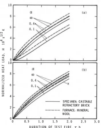
The most important input data into the numerical studies are listed in Table 1. (In the table thermal absorptivity (thermal inertia) is the term for ,/kpc, where k is thermal conductivity, p is density and c is specific heat.) The studies were devised to yield an insight into the effect of the mode of heat transfer on the results of standard fire tests. This effect will be expressed in terms of normalized heat load, H, on the test specimen and the furnace walls. The normalized heat load is, as discussed earlier,'.' a quantity ideally suited for characterizing the severity of fires, real-world fires and test fires alike.
It will be seen that, with an increase of the intensity of heat transmission from the furnace gases to the test specimen and the furnace walls, the H versus z relations
(7 meaning duration of fire test) converge upwards to two
limiting curves, one for the test specimen and one for the furnace walls.+ The degree to which these limiting curves are approached will be referred to as the 'test efficiency'. In the theoretical studies the furnace chamber was selected to have either 3 x 3 x 2.5 m or 3 x 3 x 0.5 m dimensions. A furnace with the former dimensions will be referred to as a floor furnace, one with the latter dimen- sions as a wall furnace. The absorption (emission) coeffi- cient for the furnace gases, a, has been assigned three values, 0.1,0.4, and co (the last meaning any value larger than about 5). The absorption coefficient for gases in real- world test furnaces is usually between 0.1 and 0.4, depending mainly on the nature of the fuel used. (It is generally low for gaseous fuels and higher for liquid fuels.) The properties of castable refractory brickf (marketed as KS-4), were used to simulate the test specimen. This was the material all the specimens used in the experiments
+The theorem of uniformity of normalized heat load1 claims that the normalized heat load is the same on all boundary elements of an enclosure. Clearly, the fact that the H versus s curves are somewhat different for the test specimen and the furnace walls suggests that the theorem is only a practical approximation.
¶Since this material has fairly well-defined thermal properties6 and is unaffected by repeated exposure to high temperatures, it seems to be well suited for use as standard specimen material.
HEAT TRANSMISSION IN FIRE TEST FURNACES 49
Table 1. Input variables used in the theoretical studies
Related to Variable and dimension Value
Floor furnace Principal dimension (m) 3.0
Depth (m) 2.5
Wall furnace Principal dimension (m) 3.0
Depth (m) 0.5
Furnace gas Absorption coefficient (m-') 0.1 0.4.00
Test specimen Thermal conductivity ( W m - ' K-') O.ga
Density (kg m-') 2085
Specific heat ( J kg-' K-') 1 000
Thermal absorptivity ( ~ r n - ~ s - " ~ K-') 1370
Furnace Thermal conductivity (W m-'K-') 1 .15b 0.04'
Density (kg m-') 2600 160
Specific heat ( J kg-' K-') 900 11 50
Thermal absorptivity ( J m-2s-''2K-' 1 1640 86
"Castable refractory brick. bFire clay brick.
CMineral wool (fiberfrax)
had been made from. The material of the furnace chamber was assumed to be either fireclay brick or mineral wool (fiberfrax). The thermal properties of all these materials are listed in Table 1.
The results of the studies are plotted in Figs 1-4. Figures 1 and 2 relate to floor furnace tests, and Figs 3 and 4 to wall furnace tests. The following conclusions can be drawn:
(1) The efficiency of wall furnace tests is, in general, lower than that of floor furnace tests.
(2) The efficiency of tests conducted in furnaces lined with
SPEC IMFN: CASTABLE REFRACTORY BRICK FURNACE: FIRECLAY
I
/-BRl;K,
1
0.5 1.0 1.5 2.0 2.5 3.0
DURATION O F T E S T F I R E . T h
Figure 1. The effect of convective heat transfer on the normalized heat load. Theoretical simulation of tests in a floor furnace lined with fireclay brick. (a) Heat transfer by radiation only; (b) heat transfer by radiation and natural convection.
mineral wool is higher than those conducted with furnaces made from fireclay.
(3) In floor furnace tests, convective heat transfer (in addition to radiative heat transfer) helps to improve the test efficiency if the furnace material is fireclay, but it causes little improvement if the furnace material is mineral wool.
(4) In wall furnace tests (because of the higher value of h, due to forced convection), the improvement in the test efficiency as a result of the presence of convective heat transfer is more substantial with both kinds of furnace material.
SPEC INN: CASTABLE REFRACTORY BRICK
---
FURNACE: MINERAL0 0.5 1.0 1.5 2.0 2.5 3.0
DURATION O F T E S T F I R E . T h
Figure 2. The effect of convective heat transfer on the normalized heat load. Theoretical simulation of tests in a floor furnace lined with mineral wool. (a) Heat transfer by radiation only; (b) heat transfer by radiation and natural convection.
50 M. A. SULTAN, T. Z. HARMATHY AND J. R. MEHAFFEY 8 6 4 SPECIMEN: CASTABLE REFRACTORY BRICK 2
---
FURNACE: FIRECLAY 0 0 0 . 5 1 . 0 1 . 5 2 . 0 2 . 5 3 . 0 DURATION OF TEST FIRE, r hFigure 3. The effect of convective heat transfer on the normalized heat load. Theoretical simulation of tests in a wall furnace lined with fireclay brick. (a) Heat transfer by radiation only; (b) heat transfer by radiation and forced convection.
SPECIMEN: CASTABLE REFRACTORY BRICK FURNACE: MINERAL WOOL 0 0 . 5 1 . 0 1 . 5 2. 0 2 . 5 3 . 0 DURATION OF T E S T FIRE, r h
Figure 4. The effect of convective heat transfer on the normalized heat load. Theoretical simulation of tests in a wall furnace lined with mineral wool. (a) Heat transfer by radiation only; (b) heat transfer by radiation and forced convection.
The question that arises now is: What should be taken as the minimum acceptable efficiency of standard fire tests and how should that efficiency be defined?
Clearly, if one rules out requiring major alterations in existing fire test facilities the mimimum acceptable effici- ency should be decided on with the lower efficiency wall furnace tests in mind. Based on the preceding discussions the following conditions may be considered as character- izing the minimum level of efficiency:
(1) Wall furnace test; furnace lined with mineral wool;
(2) Furnace heated with gaseous fuel, provided that
a 2 0.1 m-';
I
(3) Forced convection in the furnace chamber,
h, 2 23Wm-2K-1.
Consequently, the H versus z curve marked with X in
Fig. 4(b) can be looked upon as representing (with castable refractory brick specimens) the lower limit of acceptable test conditions. Yet this recommendation should be considered in the light of the earlier findings,' that the H versus z relation is expected to depend (even for the same type of furnace and the same values of cr and h,)
on
(1) The actual furnace volume;
(2) The ratio of the specimen surface to the surface of
i
furnace walls;(3) The material of the specimen (the test efficiency is higher for materials of lower thermal absorptivities). The last factor can be eliminated by considering castable refractory brick as reference specimen material. As to the first two factors related to the furnace construction, the operators of test furnaces must realize that the test efficiency may be lower for furnaces of volumes smaller and specimen/furnace surface area ratios larger (assuming that the furnace is lined with mineral wool) than those used in these studies, and must, therefore, take some steps to compensate for the lower efficiency. Possible measures will be discussed in a later section.
TEMPERATURE OF FURNACE GASES
It was pointed out in the section 'Theoretical Consider- ations' that T, in the theoretical analysis was interpreted as the true temperature of the furnace gases. The standard furnace temperature, Tf, as measured by nine ther- mocouples placed in the furnace chamber, is lower than T,; its value is somewhere between T, and T, (the latter denoting the average temperature of the boundary sur- faces of the furnace chamber), or perhaps even lower that T, if the thermocouples are enclosed in protective tubes. (The temperature lag caused by the protective tubes will not be taken into consideration in the discussions to follow.)
The relationship between Tf and T, can be expressed as b
Tf = T, --(T, - T,)
l + b
where b, an empirical factor, can assume any positive value which probably does not depend strongly on time. Equation (5) shows that Tf -+ T, if T, -+ T,, irrespective of
HEAT TRANSMISSION IN FIRE TEST FURNACES 5 1 the value of b. The T, + T, condition is fulfilled if either the
thermal absorptivity of the furnace boundaries, J(kpc), is very small (i.e. the boundaries are unable to absorb heat from the furnace gases), or the heat transfer coefficient, h (by radiation and convection), is very large.
T, + T, is clearly a limiting condition. Under realistic
conditions, when J(kpc) and h have finite values, the temperature of the furnace boundaries will remain below the temperature of the furnace gases, the more so the larger the value of J(kpc)/h (or, more exactly, the lower the value of the dimensionless group ho1l2/ J(kpc). Con- sequently, the standard furnace temperature (as measured by the ASTM technique) will always run below the true temperature of the furnace gases.
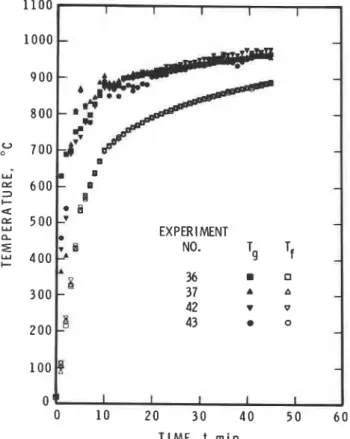
Figures 5 and 6 show the measured variation of T, and T, during the course of eight experiments conducted in the authros' floor furnace. The specimen, as in all experi- ments, was made of castable refractory brick, and the furnace walls were lined with mineral wool. The fuel was propane in the tests shown in Fig. 5 and diesel fuel in those in Fig.6. The standard furnace temperature, T,, was programmed to follow the standard temperature-time curve prescribed by ASTM E119. T, was measured by aspirated thermocouples.' The difference between T, and Tf was noticeably larger in tests conducted with propane fuel.
Propane burns with a clear flame; the effective value of the absorption coefficient, a, for its combustion products is fairly low, about 0.1. It is much higher, about 0.3, for the combustion products of diesel fuel (or liquid fuels in general). Since the coefficient of convective heat transfer is not likely influenced by the nature of the combustion
EXPERl MENT NO.
T I M E , t m i n
Figure 5. Comparison of T, and Tf in standard fire tests. Fuel:
propane. 7 , is controlled to follow the standard temperature-time curve. w L I EXPERIMENT NO. Tf
09
I I I I I 0 10 20 30 40 50 6 0 T I M E , t m i nFigure 6. Comparison of T, and T , in standard fire tests. Fuel: diesel oil. T, is controlled to follow the standard temperature-time curve.
gases the lower values of (T, - T,) in experiments conduc- ted with diesel fuel must be attributed to the higher level of radiative heat transmission, due to the higher value of a. Regarding b as approximately independent of time, Eqn (5) can be rewritten in the following form:
T, - Ts
--
- constT,-
Tf(T, - T,) is clearly a measure of potential heat trans- mission from the combustion gases to the test specimen and the furnace walls. (T, - T,), on the other hand, is a measure of the 'inadequacy' of the test, in other words, the measure of deviations from the ideal test conditions due to any reason (e.g. low emissivity of furnace gases, poor convective heat transfer, small furnace chamber, high thermal absorptivity of furnace walls or specimen). As Eqn (5a) shows (T, - T,) is proportional to (T, - T,).
The following important conclusion can now be drawn: The technique of measuring and controlling the tempera- ture of the test furnace in a way prescribed by the test standard ensures that the inadequacies of the test con- ditions are, to some extent, compensated for by a higher potential for heat transfer to the test specimen.
The recognition of this fact caused a midcourse correc- tion in the preparation of the draft of the new ASTM fire test standard. To comply with the principle of describing all performance tests in terms of well-definable process variables, it had been thought earlier that the true temperature of the furnace gases (as measured by as- pirated thermocouples) should be the variable to be measured and by which to control the test process. The newest draft of the standard reflects a return to the age-old method of measuring and controlling the temperature
52 M. A. SULTAN, T. Z. HARMATHY AND J. R. MEHAFFEY
conditions in the furnace. It is believed that this move (though not in line with the edicts of pure science) will ensure a higher uniformity of the fire test results and still allow a substantial flexibility in the future design
There remain some doubts, however, about the ade- quacy of the ASTM technique of having the 'furnace thermocouples' enclosed in steel tubes. The authors will investigate the advantages of the so-called globe ther- mocouples suggested by Danish researchers. The results of this investigation are expected to be available before the draft of the test standard is finalized.
CALIBRATION OF TEST FURNACES
It was shown in Reference 1 that the normalized heat load, H, can be evaluated from the maximum temperature rise in a slab of known thermal properties. The applicable equation is
a
H = 2.3-(T - To), (6) K is the thermal diffusivity of the slab, a is a distance below the surface of the slab, such that 0.8 < a / ~ ' ' ~ . r ' ' ~ < 1.2, (T- To), is the maximum temperature rise above the original temperature To at the depth a, occurring always after the termination of the test.
To develop a calibration procedure a decision has to be made on the length of testing and the material and dimensions of the calibration specimen. Experience has shown that discrepancies in fire test results due to inadequacies in the test parameters tend to show up most markedly during the initial 15-30min. On this account, and because 45 min is the minimum fire resistance value that practice is concerned with, it has been thought that
r = 2700s should be specified as the duration of calibra- tion tests.
As to the material of the calibration specimen, for reasons mentioned earlier it appeared logical to specify castable rafractory brick.
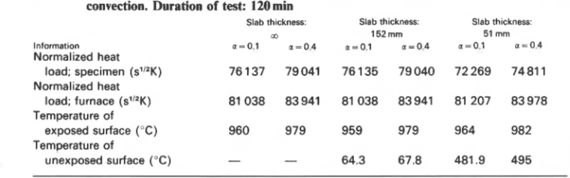
In the calculation procedure outlined in the section 'Theoretical Considerations' both the specimen and the furnace walls were assumed to be semi-infinite solids. Supplementary numerical studies revealed that under realistic conditions the finite thickness of the specimen and furnace walls had little effect on the normalized heat load. Some results of these studies are summarized in Table 2 and relate to floor furnace tests. The thickness of
Table 2. Comparison of some results of floor furnace fire test simulations. Specimen: castable refractory brick; furnace walls: mineral wool. Heat exchange by radiation and convection. Duration of test: 120min
Slab thickness: Slab thickness: Slab thickness:
m 152 mm 51 mm
lnformat~on a=0.1 a - 0 . 4 a=O.l ~ ~ 0 . 4 a=0.1 a = 0 . 4
Normalized heat
load; specimen (sl"K) 76 137 79041 76 135 79040 72 269 7481 1
Normalized heat
load; furnace (s"~K) 81 038 83941 81 038 83941 81 207 83978
the test specimen and the furnace walls was set at three values, namely oo, 152 and 51 mm. The material of the test specimen was again castable refractory brick and that of the furnace mineral wool. The heat exchange in the furnace was regarded as taking place by radiation and convection, and the absorption coefficient for the furnace gases was selected as either 0.1 or 0.4. In addition to the normalized heat load the table contains information on the temperature of the exposed and unexposed surfaces at
120min, the end of the simulated fire tests.
Clearly, the effect of thickness on the normalized heat
load is hardly noticeable as long as the thickness is in the
:
practical range. Based on this finding, 150 mm appeared,
to be an acceptable thickness for the calibration specimen.In all experimental runs performed in the authors' laboratory the test specimen was a full-size floor construc- tion: a slab of 3.66 x 4.58 m size, 152 mm thick. Because the cost of fabricating a full-size calibration specimen from castable refractory brick (composed of segments of about 300 x 300mm to facilitate heat treatment and handling) was thought prohibitively high, consideration was given to allowing the use of one segment of the specimen. This segment, to be called the measuring piece, would be. attached to a simple inexpensive construction serving essentially as an insulating cover for the opening
Temperature of
exposed surface ("C) 960 979 959 979 964 982
Temperature of
unexposed surface ("C) - - 64.3 67.8 481.9 495
of the test furnace. Figure 7 shows a calibration test assembly designed on practical and theoretical considerations.
Having decided that curve X in Fig. 4(b) is representa- tive of the minimum level of test efficiency one may now calculate the minimum acceptable value of (T- To), in the calibration tests. One reads from curve X the value of H at the suggested duration of the calibration test (45 min), then substitutes this value, together with the appropriate values of a (0.04 m) and the thermal diffusivity of the castable refractory brick, JC, into Eqn (6) to arrive at the value of ( T - To), acceptable for passing a furnace for test efficiency.
Instead of specifying ( T - To), on the bases of calcul- ations the authors have chosen the experimental avenue, for the following reasons. Curve X was arrived at on the assumption that T,, not T,, was controlled to follow the temperature-time curve (see Eqn (33*)) specified by the test standard. Based on discussions in the section 'Tem- perature of Furnace Gases', one can take it for granted that the H versus z curve for a real fire test corresponding to conditions representative of curve X would run higher. The other reason is that since JC is a function of tempera- ture and the heat transmission in the calibration specimen
HEAT TRANSMISSION IN FIRE TEST FURNACES T H E R M O C O U P L E JUNCTION 4 0 rnrn BELOW SURFACE OF MEASURING ELEMENT
Figure 7. Calibration specimen.
is transient during the test it is somewhat problematic how to select an effective value of IC to be used in Eqn 6.
The results of the experiments aimed at developing information on the minimum acceptable value for (T- To), are shown in Table 3. The experiments were conducted in the floor furnace, using propane and diesel oil as fuel. The furnace walls were lined with mineral wool. A full-scale calibration specimen (3.66 x 4.58 x 0.15m) was used and the temperature in the calibration specimen (40 mm from the surface) was measured at five places: at the center and at the centers of the four quarter-sections. In view of the earlier observation (in the section 'Tempera-
, ture of Furnace Gases') following Eqn (5a) the finding that ; values of (T- To), did not seem to depend on the nature
of fuel comes as no surprise.
Naturally, if the calibration specimen shown in Fig. 7 is used (T- To), will be measured only at one point: the center of the furnace. It can be seen from Table 3
Table 3. Temperature rise (T - To)-in experimental tests with two types of fuels
Fuel: propane
Location of Test No.
thermocouples 36 37 42 43 Center of specimen 383 380 370 372 Quarter-section 1 309 313 289 293 Quarter-section 2 340 345 327 330 Quarter-section 3 303 307 295 297 Quarter-section 4 308 306 305 305
Fuel: diesel oil
Locat~on of Tea No.
thermocouples 51 52 58 59 Center of specimen 374 372 370 374 Quarter-section 1 300 291 307 316 Quarter-section 2 350 360 341 353 Quarter-section 3 312 300 310 324 Quarter-section 4 330 308 320 326 \ MEASURING ELEMENT
that the value of (T- TO), for the center, averaged over four tests, is 376 K if the furnace is heated with propane and 373 K if it is heated with diesel oil. It appears that the minimum acceptable value for (T- T o ) , may be taken as 340K, to be calculated as the average for three calibration tests.
To check the justifiability of this recommendation some additional numerical studies were conducted, based on
-
1 I I-
-
d-
-
AVERAGE OF FOUR CALIBRATION TESTS-
---
THEORETICAL SIMULATION-
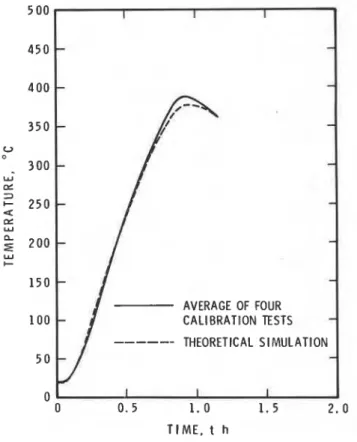
I I I 0 0 0 . 5 1 . 0 1 . 5 2 . 0 TIME. t hFigure 8. Temperature at 40 mm depth in the measuring element of the calibration specimen.
54 M. A. SULTAN, T. 2. HARMATHY AND J. R. MEHAFFEY
the experimental information on T, and T, presented in Fig. 5. These studies were different from those conducted earlier (those leading to Figs1 -4) in that T, was made to follow a (higher) course (represented by the solid points in Fig. 5) corresponding to T,'s following the standard temperature-time curve (Eqn (33*)). The temperature history of a point 40mm below the surface of the calibration specimen (castable refractory brick) is shown in Fig. 8, as derived from both calculations (dashed line) and experiments (solid curve, representing the average of four runs referred to in Table 3). It is seen that the agreement between theory and experiment is satisfactory, and that 340 K is indeed an acceptable minimum value for (T- To), in calibration tests.
HOW TO IMPROVE THE TEST EFFICIENCY?
The question now arises: What to do if a test assembly fails the calibration test, even though the furnace walls are lined with the mineral wool?
The theoretical studies have clearly indicated that the emissivity of the furnace gases has a great deal to do with test efficiency. To increase efficiency the operators of the test furnace may contemplate the folowing changes: (1) Enlarge the furnace volume;
(2) Reduce the excess air for combustion;
(3) Use some fuels that yield combustion products of higher absorption coefficient.
Clearly, the first of these solutions may involve very large capital expenditure, and therefore it may be the least desirable. The second is a practical one. If a furnace is heated with hydrocarbon gases the combustion products are non-luminous, and carbon dioxide and water vapour are the only products with emission bands of sufficient magnitude. A large amount of nitrogen and oxygen in the combustion product simply means diluting the radiating gases. Yet sometimes there is a limit to cutting down the excess air. Reducing the excess air is usually accompanied by a reduction in the furnace pressure, which cannot go below a certain limit according to the standard specification.
Converting the furnace to heating with liquid fuels is always an effective way of increasing test efficiency. Commercial liquid fuels usually burn with luminous flames of fairly high (effective) absorption coefficients (0.3 m -
'
or higher). Figure 9 shows the effect of the fuel on the emissivity of the combustion products, based on two experiments conducted with the floor furnace in the authors' laboratory. Propane was used in one and diesel oil in the other. In both, the standard furnace temperature was programmed to follow the curve prescribed by the test standard.Naturally, the conversion of a furnace to heating with liquid fuel may be a somewhat expensive solution. Experimental studies have indicated that some improve- ment in the emissivity of the furnace gases can be achieved
i f I I I
-
I-1
I\
II
II-
-
-
-
:
I
4 /-L--d-%-&<----
I#,:"
*
1
;'
-
F U E L : D I E S E L O I L---
F U E L : P R O P A N E-
1
I I I I t T I M E , t rninI
Figure 9. The emissivity of furnace gases in two standard floor
furnace tests.
by injecting through several nozzles a liquid fuel (prefer- ably one burning with a sooty, dirty flame) into the test furnace operating with gaseo,us fuel.
Although the effect of convective heat transmission on the test efficiency is usually of secondary importance some improvement in the efficiency can be achieved by employ- ing certain design measures that help increase turbulence in the furnace chamber without reducing its volume.
SUMMARY
I
On the basis of theoretical and experimental studies the factors affecting the efficiency of fire resistance test have been reviewed. Convective heat transfer may play a significant part in the heat transmission in wall test furnaces. The practice of measuring and controlling the temperature conditions in the test furnace by nine ther- mocouples evenly distributed in the furnace chamber has the advantage of improving the commensurability of results yielded by furnaces of different designs. It is essential, however, that all test furnaces be calibrated against a 'measuring element' of known properties. Three techniques are available to improve the efficiency of fire tests.
Acknowledgements
The co-operation of J. W. MacLaurin and B. C. Taber in the experi- mental work is gratefully acknowledged. This paper is a contribution of the Discussions of Building Research, National Research Council of Canada.
HEAT TRANSMISSION IN FIRE TEST FURNACES 55
NOMENCLATURE distance in the solid from surface (m)
constant (dimensionless) specific heat (J kg- 1 K-')
configuration factors (dimensionless) (overall) heat transfer coefficient (Wrn-,K-l)
coefficient of convective heat transfer (W rn-, K - l )
normalized heat load ( s ' / ~ K) thermal conductivity (W m-
'
K - ')thermal absorptivity (J m- s- ' I 2 K - ')
radiative heat flux (W m - 2 ) time(s)
time increment(s)
(absolute) temperature (K) distance between mesh points (m)
E emissivity of solid surface (dimensionless) P density (kg m - 3,
K thermal diffusivity (m2s-')
z duration of test fire (s (min, h)) Subscripts
f of 'furnace', as measured by the standard technique
g of furnace gases
m maximum
s of the surfaces of furnace chamber
1,2 (first subscript) of specimen and of furnace walls, respectively
0 1 2 , . . (subscript outside parentheses) at the surface, at Ax from the surface , at 2Ax from the surface, etc.
. .
Greek letters Superscripts
absorption (emission) coefficient (m-') 0 at t = O
CI
j =0,1,2
,...
at t = O , a t t = A t , a t t=2At,etc.A,,, A,,
transmissivities of furnace gases(dimensionless)
REFERENCES
1 . T. Z. Harmathy, Fire and Materials 5, 11 2 (1 981 ). 6. T. 2. Harmathy, Properties of Building Materials at Elevated 2. E. R. G. Eckert and R. M . Drake, Heat and Mass Transfer, Temperatures, National Research Council of Canada, Division of
McGraw-Hill, New York (1959). p. 407. Building Research, NRCC 20956 (1983).
3. Techanical Data on Fuel, edited by H. M . Spiers, 4th edn, British 7. P. A. Crocem, a Study of Room Fire Development: The Second National Committee, World Power Conference, London (1 943). Full-Scale Bedroom Fire Test of the Home Fire Project (July 24,
p. 182. 7974). Volume 11-Analysis of Test Results, FMRC Ser. No. 4. Advances in Heat Transfer, Vol. 13, edited by J. P. Harnett and 2101 1.4, Factory Mutual Research, Norwood, M A (1975).
T. F. Irvine. Academy Press, New York (1 977). p. 15.
1
5. T. 2. Harmathy and J. R. Mehaffey. Fire and Materials 6, 27I (1 982).
T h i s paper is being d i s t r i b u t e d i n r e p r i n t form by t h e I n s t i t u t e f o r Research i n C o n s t r u c t i o n . A l i s t of b u i l d i n g p r a c t i c e and r e s e a r c h p u b l i c a t i o n s a v a i l a b l e from t h e I n s t i t u t e may be o b t a i n e d by w r i t i n g t o t h e ~ u b l i c a t i b n s S e c t i o n , I n s t i t u t e f o r RCsearch i n C o n s t r u c t i o n , N a t i o n a l Research C o u n c i l of C a n a d a , O t t a w a , O n t a r i o ,
KIA 0R6.
C e document