Accelergy: An Architecture-Level Energy
Estimation Methodology for Accelerator Designs
The MIT Faculty has made this article openly available.
Please share
how this access benefits you. Your story matters.
Citation
Wu, Yannan Nellie et al. "Accelergy: An Architecture-Level Energy
Estimation Methodology for Accelerator Designs." International
Conference On Computer Aided Design (ICCAD), November 2019,
Westminster, Colorado, United States of America, Institute of
Electrical and Electronics Engineers (IEEE), November 2019
As Published
https://iccad.com/2019_accepted_papers
Publisher
Institute of Electrical and Electronics Engineers (IEEE)
Version
Author's final manuscript
Citable link
https://hdl.handle.net/1721.1/122044
Terms of Use
Creative Commons Attribution-Noncommercial-Share Alike
Accelergy: An Architecture-Level Energy Estimation
Methodology for Accelerator Designs
Yannan Nellie Wu
MIT Cambridge, MA [email protected]Joel S. Emer
NVIDIA, MIT Westford, MA [email protected]Vivienne Sze
MIT Cambridge, MA [email protected]ABSTRACT
With Moore’s law slowing down and Dennard scaling ended, energy-efficient domain-specific accelerators, such as deep neural network (DNN) processors for machine learning and programmable network switches for cloud applications, have become a promising way for hardware designers to continue bringing energy efficiency improve-ments to data and computation-intensive applications. To ensure the fast exploration of the accelerator design space, architecture-level energy estimators, which perform energy estimations without requiring complete hardware description of the designs, are critical to designers. However, it is difficult to use existing architecture-level energy estimators to obtain accurate estimates for accelerator designs, as accelerator designs are diverse and sensitive to data patterns. This paper presents Accelergy, a generally applicable en-ergy estimation methodology for accelerators that allows design specifications comprised of user-defined high-level compound com-ponents and user-defined low-level primitive comcom-ponents, which can be characterized by third-party energy estimation plug-ins. An example with primitive and compound components for DNN accel-erator designs is also provided as an application of the proposed methodology. Overall, Accelergy achieves 95% accuracy on Eyeriss, a well-known DNN accelerator design, and can correctly capture the energy breakdown of components at different granularities. The Accelergy code is available at http://accelergy.mit.edu.
1
INTRODUCTION
Since Moore’s law has been slowing down and Dennard Scaling has ended, energy consumption has become a critical concern for hardware designs. Domain-specific accelerators have become an essential alternative to general-purpose processors, which often result in the high energy consumption and slow processing when running data and computation intensive applications [7]; accord-ingly, in recent years, many hardware designers achieve energy efficiency improvements by using accelerator designs (e.g., DNN processors for machine learning [1, 4, 5, 17] and programmable network switches for cloud applications [8, 20]). These accelerators are designed to exploit the characteristics of specific application domains, and thus improve energy efficiency.
Often, accurate energy consumption is predicted only after com-pleting the physical design layout. Although post-layout energy estimation gives high accuracy, it hinders design space exploration for two reasons: (1) significant design effort overhead, as designers have to complete almost the entire design to obtain the post-layout information, and (2) slow simulation time, as the estimation is done on gate-level components. To achieve faster design space explo-ration, the energy estimation needs to be performed at an earlier design stage where the complete hardware description is not a
prerequisite (e.g., at the architectural stage). Architecture-level en-ergy estimators take in an architecture description and runtime action counts for a specific workload, and directly estimate the energy consumption. The architecture description describes the components in the design (e.g., there is a cache and an ALU in the processor design), and their respective hardware attribute values (e.g., the cache is 32kB and the ALU has a data-width of 64 bits). The runtime action counts describe how the components in the design are used (e.g., the cache is read 200 times). In this work, we propose Accelergy, an architecture-level energy estimation methodology that addresses the potential challenges associated with early-stage energy estimations of accelerator designs.
1.1
Related Work
Existing architecture-level energy estimation tools can be classified into three categories: component estimators, processor estimators for designs that are composed of a fixed set of components, and design-specific energy tables for accelerator designs.
Component estimators focus on generating energy models for a specific type of components rather than the entire design [9, 15, 21]. CACTI [15] focuses on the energy estimation of memory components, such as caches and SRAMs. Orion [9, 21] provides analytical models for the energy estimation of networks-on-chip (NoCs). Although these component estimators provide an in-depth understanding of the specific component’s energy consumption, they cannot generate a holistic view of the entire design.
Processor estimators focus on processor energy estimations for de-signs with architectures that are composed of a fixed and limited set of compound components. A compound component is a high-level function unit that contains several low-level primitive components or other high-level function units as its sub-components (e.g., a cache is a compound component with comparators and SRAM modules as its sub-components). Among such tools, Wattch [2], McPAT [14] and PowerTrain [12] focus on CPU energy estimations, and GPUWattch [13] focuses on GPU energy estimations. Describ-ing designs usDescrib-ing compound components allows the runtime action counts to be generated in terms of high-level compound actions, which are defined as composites of the low-level actions of the sub-components. Therefore, when the low-level details of the com-pound action change, the runtime action counts do not need to be regenerated, speeding up the energy evaluation process. However, these existing processor estimators use a fixed and limited set of compound components, and therefore do not provide the flexibility for designers to define arbitrary accelerator designs, as shown in Fig. 1. Since accelerator designs vary significantly from one to an-other (e.g., DNN accelerators vs. database accelerators), providing a flexible way to model the diverse design space becomes essential.
Figure 1: The CPU components cannot describe accelerators.
Design-specific energy tables for processor energy efficiency anal-ysis provide high accuracy for specific target design cases [1, 10, 16, 19, 22]. However, these tools only generate design-specific tables for those components that are specific to the design associated with the tool. For example, SnaPEA’s [1] energy modeling table uses primitive components with predefined attributes, such as a 16-bit fixed point PE. Such tables are too design-specific to be used by other designs. Furthermore, many of these generated tables only have entries for the primitive components instead of the compound components. Such exceedingly fine-grained tables make the en-ergy evaluation tedious and describing designs using hundreds of low-level primitive components might result in overlooking com-ponents.
1.2
Additional Challenges
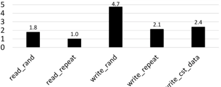
Since different types of actions on a component (e.g., read and write are two different actions on a memory block) result in distinct energy consumption, to achieve accurate energy estimations of accelerator designs, designers are required to create a large enough repertoire of action types for each component to accurately reflect the energy consumption of the component. Furthermore, since accelerators are highly specialized for specific applications, they tend to exploit the domain-specific data patterns by efficiently or-chestrating data (e.g., performing repeated accesses to the same address of a memory block for data reuse). Thus, for accelerators, these types of actions on components appear more frequently than they do in general-purpose processors. Fig. 2 shows an example of the post-layout energy consumption of actions on a flipflop-based register file with write enable. Among the listed actions, *_rand means access to the memory with random address (and data), *_re-peat means the address and data of the action are always the same, and write_cst_data means the same data is written across multiple cycles. As shown in the figure, for different actions the energy-per-action can vary by 2× even if they are both reads. Therefore, if a certain action of a component is popular (e.g., write_cst_data action becomes prevalent due to high sparsity), classifying actions more precisely is necessary to avoid significant estimation error.
Lastly, being able to derive primitive component energy estima-tions from a variety of primitive component estimators, including those from a third party, is important for achieving high flexibility. The primitive component estimators can range from technology-dependent energy tables [1, 4, 16] to general-purpose estimation tools [2, 13, 14]. As new technologies emerge, the energy consump-tion of a specific operaconsump-tion in the architecture may vary significantly depending on its underlying technology. For example, in-memory computation (e.g., with RRAM) helps to greatly reduce the amount of energy spent on performing a multiply and accumulate (MAC).
1.8 1.0 4.7 2.1 2.4 0 1 2 3 4 5
Figure 2: Post-layout energy consumption of different ac-tions on a flipflop-based register file with write enable. En-ergy normalized to the idle register’s enEn-ergy per action.
However, the users of conventional processor estimators are nei-ther able to express that the design contains a special component nor can they characterize the special component using their own third-party primitive component estimators.
1.3
Contributions
To address the above mentioned challenges, we present Accelergy1, a generally applicable methodology for performing architecture-level energy estimation on accelerator designs. This paper:
• presents a framework that allows users to
– describe their design with their own set of design-specific compound components with attributes and actions. – describe compound components composed of primitive
components whose attributes and actions are character-ized by energy estimation plug-ins.
– generate energy estimations for the design with workload generated runtime action counts.
• provides an example application of Accelergy for DNN ac-celerators.
2
HIGH-LEVEL FRAMEWORK
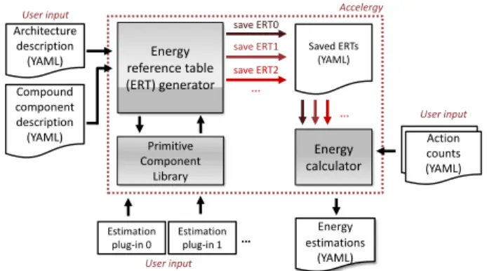
Fig. 3 shows a high-level block diagram of the Accelergy estima-tion framework. Similar to the existing architecture-level energy estimators, Accelergy takes in an architecture description and run-time action counts, which are based on a specific workload that is generated by performance models (e.g., cycle-accurate simulators or analytical models). In addition to the architecture description and runtime action counts, Accelergy also takes in compound com-ponent descriptions to describe the properties of the compound components in a specific design (see Section 3.3) and generates an energy estimate for the design. All the input and output files are in YAML format.
As shown in Fig. 3, Accelergy can interact with multiple energy estimation plug-ins. Each estimation plug-in is composed of one or more component energy estimators that estimate the energy consumption for primitive components in Accelergy’s primitive component library. This feature allows Accelergy to provide esti-mations for many technologies. Estimation plug-ins must adhere to the estimation plug-in interface defined by Accelergy. To show the flexibility of the interface, we provide two example estimation plug-ins: (1) Aladdin’s [19] 40nm component-wise energy table,
Accelergy User input Action counts save ERT2 save ERT1 save ERT0 Energy reference table (ERT) generator Estimation plug-in 0 Energy calculator … … … Primitive Component Library Saved ERTs (YAML) Action counts (YAML) Energy estimations (YAML) User input Architecture description (YAML) User input Estimation plug-in 1 Compound component description (YAML)
Figure 3: High-level block diagram of Accelergy framework. which is a design-specific energy table, and (2) CACTI [15], which is an open-source tool for general memory components (e.g., SRAMs). Accelergy has two main parts: (1) the energy reference table (ERT) generator and (2) the energy calculator. The ERT generator is re-sponsible for parsing the architecture and compound component descriptions and querying the appropriate estimation plug-ins to generate energy estimates of the components in the design. The generated energy estimates are saved in the form of ERTs, which record the energy-per-action for different action types associated with the primitive and compound components in the design (e.g., the action types and energy-per-action specified in Fig. 2 are ERT entries for the specific register file). For each action, the related ERT entry must have sufficient information to calculate the en-ergy for any value of the arguments associated with the action (see Section 3.3).
Automatic design exploration tools, such as Timeloop [16], re-quire fast energy consumption evaluations. To enable the integra-tion of Accelergy with such tools, the generated ERTs for a hardware design are saved, so that they can be reused for action counts from different workloads. This avoids re-parsing the design descriptions and re-querying the component estimators.
The energy calculator is responsible for parsing the action counts and the saved ERTs. The energy estimations of the components in the design are generated by combining the related entries in the action counts and the saved ERTs.
3
CONFIGURATION LANGUAGE
This section presents the detailed semantics of the configuration language used by Accelergy.
3.1
Object-Oriented (OO) Approach
Designs often contain or share multiple components of the same type and each component has different values for its attributes. For example, SRAMs are present in most of the designs, but each SRAM has different technology, depth, width, number of banks, etc. To avoid enumerating every component’s attributes and asso-ciated actions in the design, Accelergy uses an OO approach by introducing the concept of a component class, which is similar to a class in an OO language. A component class’ data members are its hardware attributes, and its member functions are its actions. The components that share the same set of hardware attributes and actions are instances of their component class (e.g., an SRAM block
of depth 128 and an SRAM block of depth 512 both belong to the same SRAM class). All the component instances derived from the same class can (1) inherit or override the default hardware attribute values specified by the class to distinguish between each other, and (2) perform the same set of actions defined by the class. In this way, with the description of the component classes, the component instances can be succinctly described in terms of its component class name and a set of hardware attribute values used to override the defaults (if there are any).
3.2
Primitive Component
A primitive component is a component at the finest granularity. It is an instance of a primitive component class. Example 1 shows a description of a counter class. To describe primitive component classes, the set of essential hardware attributes and actions are needed. Primitive classes are listed in Accelergy’s primitive compo-nent library as a YAML list. Since many accelerator designs share the same set of primitive components (e.g., SRAM and adder), the primitive component library can be shared across different designs to avoid regeneration of such lists. The estimation plug-ins generate ERTs for primitive components.
Example 1: a counter primitive component class 1 name: c o u n t e r # c l a s s name 2 a t t r i b u t e s : # d e f a u l t a t t r i b u t e s 3 t e c h n o l o g y : 65 nm 4 d a t a w i d t h : 16 5 a c t i o n s : # l i s t o f a c t i o n s 6 - name: cou nt 7 - name: idle
3.3
Compound Component
A compound component is defined as a high-level function unit that consists of several primitive components or other high-level function units, which we refer to as its sub-components. Describing designs in terms of compound components simplifies runtime statis-tics generation, produces succinct design description, and reduces energy estimation errors caused by overlooking some primitive components. However, since the accelerator design space is very di-verse, it is hard to provide a fixed set of compound components that can be used for all possible designs. To address the problem of diver-sity in the design space, Accelergy allows user-defined compound components.
Compound components are instances of compound component classes, which are defined by the user in the compound component description file as an input to Accelergy. As compound components inherently involve lower-level components, to define a class of compound components, the following needs to be specified: (1) a set of attributes, (2) a set of sub-components, and (3) a set of compound action names and definitions.
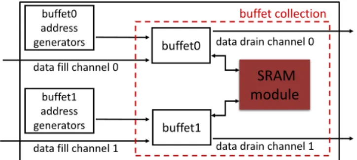
3.3.1 Smart buffer unit. In order to illustrate the semantics clearly, we use the idea of a smart buffer unit as a compound com-ponent example. The smart buffer unit has a storage structure that is a simplified version of a proposed accelerator idiom, the buffet collection [18], and address generators that supply addresses to the storage structure.
SRAM
module
buffet0 address generators
data fill channel 1 data drain channel 1 buffet1
buffet1 address generators
buffet0 data fill channel 0
data drain channel 0 buffet collection
Figure 4: Simplified block diagram of smart buffering unit with 2 buffets mapped to a SRAM in the buffet structure.
Fig. 4 shows the block diagram for a smart buffer unit, which contains a buffet collection and multiple address generators. A buffet collection is a storage structure that uses a decoupled access-execute approach for memory fills (writes) and drains (reads). At a high level, a buffet collection contains one or more buffets and a physical memory. Each buffet is mapped to a certain portion of the physical storage (e.g., several banks of the SRAM) and contains the logic to arbitrate read and write requests specific to its portion of the physical memory. For example, if a read is requested for an address that is not written yet, the buffet arbitration logic will block the read request until valid data is available in the buffet. The requests to each buffet are generated using a set of address generators that can be configured to generate different sequences of addresses. These address generators are essentially counters that count in specific patterns. Since the smart buffer unit has multiple underlying lower-level components, by Accelergy’s definition, it can be represented as a compound component. We are going to use a smart buffer as an example compound component class. For simplicity, we assume that the address generators in the smart buffer are an array of counters that have identical hardware attributes.
3.3.2 Compound Attributes and Sub-component Classes. To de-scribe a compound component class, a list of relevant hardware attributes to the class’s hardware properties should be specified. For example, memory width, height and port information can be used to describe a smart buffer. Example 2 shows the description of the smart buffer class.
Since the smartbuffer class contains lower-level components, Accelergy uses the subcomponents field to illustrate this hierarchi-cal relationship between the compound class and its underlying lower-level components. Therefore, for the smartbuffer class, the following sub-components need to be reflected in the component class description: (1) buffet_collection: another compound compo-nent derived from the buffet_collection class, which contains buffets and SRAM (already defined as an existing compound component class). (2) addr_generators[0:nBuffets-1]: an array of identical ad-dress generators, which are primitive components derived from the counter class. Note that [0:N-1] is the Accelergy grammar for specifying an array of N identical elements.
In this example, we assume that the buffet_collection class is al-ready defined as an existing compound component class. As shown in Example 2, each sub-component is fully defined by a set of neces-sary hardware attributes. The sub-component’s attributes could be
directly assigned as numerical values, or inherit the attribute value from the higher-level component class, or mathematical operations on the compound attributes.
Example 2: a smart buffer compound component class 1 name: s m a r t b u f f e r # c l a s s name 2 a t t r i b u t e s : # d e f a u l t a t t r i b u t e s 3 wi dth : 16 4 de pth : 25 5 n B a n k s : 1 6 n R d P o r t s : 1 7 n W r P o r t s : 1 8 n B u f f e t s : 1 9 s u b c o m p o n e n t s : # l o w e r − l e v e l components 10 - name: a d d r _ g e n e r a t o r s [0:nBuffets -1] 11 cl ass : c o u n t e r 12 a t t r i b u t e s : 13 c o u n t _ m a x : d ept h 14 - name: b u f f e t _ c o l l e c t i o n 15 cl ass : b u f f e t _ c o l l e c t i o n 16 a t t r i b u t e s : 17 wi dth : wi dth 18 de pth : de pth #map t o top − l e v e l 19 n B a n k s : n B a n k s 20 n R d P o r t s : n R d P o r t s 21 n W r P o r t s : n W r P o r t s 22 n B u f f e t s : n B u f f e t s 23 a c t i o n s : 24 - name: idle # a c t i o n w i t h o u t a r g s 25 s u b c o m p o n e n t s : 26 - name: a d d r _ g e n e r a t o r s [0] 27 a c t i o n s : 28 - name: idle 29 r e p e a t : n B u f f e t s 30 - name: b u f f e t _ c o l l e c t i o n 31 a c t i o n s : 32 - name: idle 33 r e p e a t : 1 34 - name: b u f f e r _ a c c e s s # a c t i o n w i t h a r g s 35 a r g u m e n t s : 36 n D r a i n : 0.. nRdPorts -1 37 nF ill : 0.. nWrPorts -1 38 s u b c o m p o n e n t s : 39 - name: a d d r _ g e n e r a t o r s [0] 40 a c t i o n s : 41 - name: g e n e r a t e 42 r e p e a t : n D r a i n + nFi ll 43 - name: b u f f e t _ c o l l e c t i o n 44 a c t i o n s : 45 - name: a c c e s s 46 a r g u m e n t s : 47 n D r a i n : n D r a i n 48 nF ill : nF ill
3.3.3 Compound Action Configuration. Besides the attributes assignment and sub-component descriptions, another essential part of a compound class description involves describing high-level
compound action types. Compound action types allow designers to easily redesign low-level details of the compound components without regenerating action counts, and to reduce the amount of action counts needed.
A compound action is defined as an aggregate of the lower level sub-components’ action types. Example 2 illustrates the simplest example of a compound action definition – the idle action of smart-buffer (line 24). For a smart smart-buffer, the idle action consists of an idle action of buffet_collection and the idle actions of address generators in the addr_generators array. Since all of the address generators in the array are identical, their idle actions consume the same amount of energy. Therefore, instead of enumerating the idle sub-component actions of all the address generators, Example 2 (line 26-29) simplifies the description by only specifying the first address generator, namely addr_generators[0], and using repeat (default is 1) to specify the number of idle sub-component actions needed to describe the compound action.
However, some action types can have multiple energy-per-action values. For example, the energy-per-action of a smart buffer’s buffer_access action depends on the number of fills and drains in-volved, which is related to the number of active buffets in the buffet collection. Another example is the multicast action of NoC designs, where the energy-per-action value depends on the number of desti-nations. To avoid enumerating each possibility as a separate action type, Accelergy defines such actions as actions with arguments, with the arguments provided as part of the action counts. Example 2 shows an example description of compound action with arguments (line 34), where a compound action buffer_access needs two runtime arguments: (1) nDrain: number of drains, and (2) nFill: number of fills. The two additional arguments are used to characterize how many address_generators are active, and to specify how many fills and drains happen in the buffet_collection.
3.4
Architecture Description & Action Counts
In addition to the compound component description, the architec-ture description is another important part of the input into Accel-ergy. The architecture description expresses the correspondence between component classes and component names. It allows Accel-ergy to link the component names and the generated ERTs, such that the action counts for the component can be correctly inter-preted. The hierarchical architecture design can be represented as a tree structure in YAML; each node of the tree is a YAML dictionary. Each internal node of the tree contains the attributes (if any) that can be shared among its child nodes. Each leaf node of the tree specifies the name of a component in the design and its component class name, as well as the component’s attribute values.
The final input to Accelergy are the action counts, which refer to the runtime information generated by the performance model. Similarly, action counts can be described as a tree, whose nodes are YAML dictionaries. The leaf nodes of the tree contain component names and the corresponding counts for each action type.
4
EXAMPLE DNN APPLICATION
To demonstrate Accelergy’s methodology for architecture-level ac-celerator design energy estimations, we constructed an example
application of Accelergy for DNN accelerator designs. A set of prim-itive components are used to describe the compound components in DNN accelerators. To accurately reflect the energy consumption of each primitive component, we associate it with a series of action types, each with a different energy-per-action. Table 1 summarizes some example primitive components. The hardware attributes col-umn lists the major attributes that need to be provided for the full characterization of the component. The action type column specifies the important action types on the component.
Table 1: Selected components, hardware attributes, and ac-tion types in DNN primitive component library
Primitive Components
Hardware Attributes Action Types
SRAM
width random_read
depth random_write
# of read ports repeated_read
# of write ports repeated_data_write
# of banks bypassed_read
MAC
bitwidth random_MAC
# of pipeline stages constant_MAC gated_MAC zero_gated_MAC
counter count limit count
router
FIFO width random_transfer
crossbar input ports repeated_transfer crossbar output ports gated_transfer
wire data width random_transfer
wire length repeated_ transfer
To generate action types that cause significantly different energy-per-action values, we considerPower = αCVD D2 f , where C is the total switching capacitance,VD D is the supply voltage,α is the switching activity which indicates how often the capacitance is charged, andf is the clock frequency. We classify the main causes of the differences in energy-per-action values into four categories: (1) action property (2) data property (3) clock gating (4) design-specific optimizations.
Action property refers to the most basic definitions of the actions (e.g., read and write actions in SRAM have different action properties since they affect the bit-lines and sense amplifiers in different ways). Therefore, the action property affects theα value in the power equation. Many existing energy estimators [2, 14, 15, 21] distinguish action types according to their action properties. As shown in Table 1, Accelergy also uses action properties to help classify action types (e.g., for SRAM, *_read all belong to the class read actions, and *_write all belong to the class of write actions).
Data property refers to the values of the data being processed. Frequent changes in data values increase the switching activity, i.e., theα value in the power equation, and therefore increase the energy consumption. For example, reading random data from a random address of a SRAM-based buffer consumes much more energy than reading the same data from the same address, as the data and address do not change in the latter case. Since the data pattern is mostly random for general-purpose processing units, data values are traditionally assumed to be random in the conventional energy estimators [2, 13–15]. However, since accelerators tend to target applications with special data patterns (e.g., many DNN
applications are very sparse), considering data property is critical for an accurate estimation. Therefore, Accelergy further classifies the action types according to the data being processed. For example, in Table 1, random_MAC is a MAC operation on two operands with random data values, and constant_MAC is also a MAC operation, i.e., same action property, but operates on two operands with constant data values, i.e., different data property.
Clock gating refers to the difference in energy consumption re-sulting from the clock gating cells inserted by the CAD tools. Since clock gating turns off the clock, it reduces theα value to zero in the power equation. Therefore, when a component is completely clock gated, no matter what the input data values are, it consumes minimal energy. Accelergy adds action types related to clock gating for each component to address the difference in energy consump-tion. For example, in Table 1, Accelergy distinguishes between constant_MAC and gated_MAC action types; although both of the actions perform the same operation, i.e., same action property, and involve no data value change, i.e., same data property, a constant MAC consumes dynamic clock network energy, while a gated MAC only consumes static energy.
Design-specific optimization refers to the hardware optimizations on throughput or energy implemented in specific accelerator de-signs. Accelergy allows users to add design-specific action types on top of the default action types. For example, due to the high sparsity in DNN applications, many DNN accelerators perform zero-gating on their MAC, i.e., detect zero operands and skip zero MACs. This manual optimization has a significant impact on the MAC’s energy consumption. Accelergy specifies this design-specific action types as a zero_gated_MAC for the MAC component. This action involves the energy consumption of the zero-detection logic, which is spe-cific to the design, and the MAC component. Another common design-specific optimization in accelerator designs is to directly bypass the data from a write request as the response to a read re-quest to the same address. This motivates Accelergy to specify the bypassed read action type for the SRAM buffer.
5
EXPERIMENTAL RESULTS
In this section, we first validate Accelergy’s estimation methodology by comparing the estimated energy with post-layout results (which we use as the ground truth) and then demonstrate the accuracy of Accelergy’s energy estimation at different granularities to show the importance of having a rich collection of action types and components.
5.1
Experimental Setup
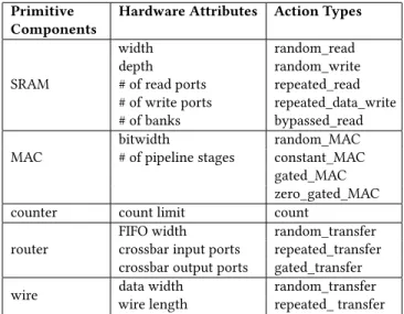
Our energy estimation validation and evaluation are performed on a well-known DNN accelerator design, Eyeriss [4], whose high-level block diagram is shown in Fig. 5. The accelerator design is written in RTL, synthesized, and placed-and-routed in a 65nm technology. We specified the Eyeriss design with the DNN primitive com-ponents outlined in Section 4, which has 11 primitive comcom-ponents in total. The energy-per-action values in the library are generated using post-layout simulations of small modules (e.g., the MAC com-ponent). The overhead of generating RTL descriptions of such small modules is considered trivial compared to the effort for generating the entire design’s hardware description.
WeightsNoC IfmapNoC PsumWrNoC PsumRdNoC Global Buffer (GLB) Weights GLB Shared GLB PE PE
…
PE PE PE PE…
PE PE PE…
…
…
…
PE array 12x14 weights_spad ifmap_spad psum_spad MAC PE instanceIfmap = input feature map Psum = partial sum PE = processing element *_spad = *_scratchpad
Figure 5: High-level architecture of Eyeriss [4] design.
5.2
Simulation Framework
To emulate a practical use case of the methodology, where we assume the RTL for the design is not available, we built a parame-terizable cycle-level DNN simulator in Python as the performance model. The simulator has 168 PEs in the PE array, 108kB global buffer, and NoC structures that use a Y bus and 12 X buses. The zero-gating optimization inside the PEs, i.e., gate MAC and weights_spad when input feature map data is zero, is also modeled.
We assume that every design evaluation involves a software simulation at the architecture-level, so the effort associated with constructing the simulator is not considered as extra overhead. Since Eyeriss cannot be easily simulated using existing standard simulators (e.g., Aladdin [19]), we used a custom cycle-level DNN simulator in the experiment. However, users can use any simulator to generate the action counts, as long as the generated statistics ad-here to Accelergy’s action counts format. To accelerate the process of producing the design description and action counts, a statistics collector is built into the cycle-level simulator to automatically col-lect such statistics. Since Accelergy interprets designs in terms of their compound components, the statistics collector only collects ac-tion counts for the compound components (e.g., cache acac-tion counts instead of SRAM action counts). Overall, the Eyeriss architecture uses 9 primitive components from the DNN primitive component library, and 6 user-defined compound components for describing high-level functional blocks.
5.3
Energy Estimation Validation
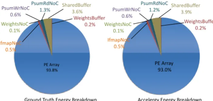
Absolute energy consumption refers to the total energy consumed by the design. It determines the design’s minimum energy resource requirement, so we first compare the absolute energy consumption estimation obtained using Accelergy. The validation workload uses input data from the Imagenet dataset [6] and weights data from Alexnet [11], both quantized to 16 bits. The validation result is shown in Fig. 6. The total estimated energy is within 5% of the post-layout results.
Relative energy breakdown refers to the percentage of energy each component consumes relative to the total energy consumed by the design. It shows the energy impact of the components in the design, so we then validate the estimated relative energy breakdown across the important modules in the design. Fig. 6 labels the relative energy breakdown of the GLBs, the NoCs, and PE array for ground truth and the Accelergy estimation. The relative difference between the corresponding breakdown values are within 8%.
PE Array 93.8% WeightsBuffer 0.2% SharedBuffer 3.6% PsumRdNoC 1.3% PsumWrNoC 0.6% WeightsNoC 0.1%
Ground Truth Energy Breakdown Accelergy Energy Breakdown
IfmapNoC 0.5% PE Array 93.0% PsumRdNoC 1.2% IfmapNoC 0.5% WeightsNoC 0.1% SharedBuffer 3.9% WeightsBuffer 0.2% PsumWrNoC 0.6%
Figure 6: Relative energy breakdown of Eyeriss [4].
5.4
PE Energy Breakdown Evaluation
As shown in Fig. 6, the PE array consumes the majority of the total energy. In this section, we look into finer granularity esti-mations of the PE array. Evaluations of three different types of estimation methodologies are performed to show the importance of Accelergy’s rich collection of action types and components.
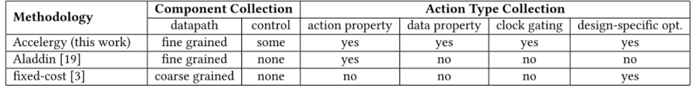
5.4.1 Different Estimation Methodologies. We will compare Ac-celergy with two other methodologies used in evaluating specific accelerator designs and evaluate the benefits Accelergy can bring. We first consider the energy estimation method proposed in Al-addin [19]. AlAl-addin focuses on the components in the datapath, and classifies the action types in terms of different action properties, but does not consider other contributing factors described in Sec-tion 4. Specific to Eyeriss, this method does not consider control logic and is not able to recognize the design-specific action types (e.g., zero_gated_MAC). We then look at the fixed-cost method pro-posed for DNN energy estimation [22] that extends Eyeriss’ energy estimation framework [3]. The fixed-cost method tends to sim-plify the types of components into coarse categories, e.g., memory components that belong to the same level of memory hierarchy are treated as the same component, and therefore share the same energy-per-action. When classifying action types, the fixed-cost method takes into consideration the design-specific optimizations but ignores other contributing factors (e.g., action property, data property, etc.). Specific to Eyeriss design, this method does not consider control logic and does not distinguish memory compo-nents inside the PEs. Table 2 summarizes the differences across three types of methodologies in terms of action type collection and component collection. 100% 95% 88% 78% 0% 20% 40% 60% 80% 100%
ground truth Accelergy Aladdin fixed-cost
Ener
gy
Consump
ti
on
Figure 7: Total energy estimations for PE array using three different methodologies. 0.10 0.12 0.14 0.16 0.18 0.20 0.22 0.24 0.26 0 2 4 6 8 En er gy Con sumption (µ J) PE Index
ground truth Accelergy
Aladdin fixed-cost
Figure 8: Energy breakdown estimation of PE array on se-lected PE instances using three different methodologies.
0 20 40 60 80 100
ifmap_spad psum_spad weights_spad MAC
Ene rgy Consump tion (n J ) ground truth Accelergy Aladdin fixed-cost
Figure 9: Energy breakdown within a single PE instance.
5.4.2 Energy Evaluations. We evaluate the energy estimation ac-curacy of the PE array from three aspects: (1) total PE array energy, which consists of 168 PEs, shown in Fig. 7, (2) energy breakdown across selected PEs within the PE array, shown in Fig. 8, and (3) energy breakdown within a PE instance, shown in Fig. 9.
According to Fig. 7, Accelergy achieves the highest accuracy in terms of total energy consumption. Fixed-cost achieves much less accurate total energy estimation. Since fixed-cost has a much smaller collection of components, i.e., it ignores the control logic, minor datapath, and idle cycles, it overlooks a significant amount of energy. Aladdin also ignores those components, but it produces a higher accuracy than fixed cost on total energy estimation. The higher accuracy in Aladdin, however, is a result of underestimat-ing the control logic and overestimatunderestimat-ing the PE datapath logic, as Aladdin’s action type collection does not include design-specific action types, i.e., the ones related to zero-gating optimization.
Fig. 8 shows the energy breakdown of selected PEs within the PE array. Since different PEs process data with different amounts of sparsity, e.g., PE 1 processes 66% sparse data and PE 2 processes 72% sparse data, they consume different amounts of energy due to Eyeriss’ zero-gating optimization. As both Accelergy and fixed-cost consider design-specific action types, they can capture the relative energy differences across the PEs with reasonable accuracy. Aladdin, without considering design-specific action types, fails to reflect the energy difference between PEs. Instead, it predicts that all the PEs have the same energy consumption.
Table 2: Comparisons between different estimation methodologies in terms of component collection and action type collection.
Methodology Component Collection Action Type Collection
datapath control action property data property clock gating design-specific opt.
Accelergy (this work) fine grained some yes yes yes yes
Aladdin [19] fine grained none yes no no no
fixed-cost [3] coarse grained none no no no yes
Fig. 9 shows the energy breakdown of components within a sin-gle PE instance, PE 0 is used as an example. Accelergy is able to capture the energy breakdown inside the PE instance. The other two methods, however, both fail to reflect the ground truth energy breakdown. Due to sparsity, gated read, which is modeled as idle action, on weights_spad and zero_gated_MAC on MAC should hap-pen frequently. Aladdin fails to capture these action types related to design-specific optimization and overestimates the energy for weights_spad and MAC. In addition to zero-gating, the high sparsity on input feature maps also cause the partial sum values to change infrequently. The almost-constant partial sum data values lead to a significant amount of repeated data write, which involves minimal switching activities on the data wires, to psum_spad. Since Aladdin does not recognize action types related to data properties, it over-estimates psum_spad’s energy consumption. Fixed-cost treats all the scratchpads in the PE as the same component, as they belong to the same level of memory hierarchy. Furthermore, fixed-cost also does not distinguish action types according to action proper-ties. Therefore, under fixed-cost, all of the actions on scratchpads share the same energy-per-action value. In reality, however, the scratchpads are very different in sizes, e.g., weights_spad is more than 10× larger than ifmap_spad, and even use different underlying memory design, e.g., SRAM versus register file. Therefore, without a rich enough component collection and action type collection, fixed-cost is not able to correctly capture the energy consumption of the components within the PE.
6
CONCLUSION
In this paper, we present Accelergy, a methodology for creating broadly applicable and accurate architecture-level energy estima-tion frameworks for accelerator designs. We propose a configura-tion language that helps the designers to describe their own high-level function units as compound components, as well as define their own compound actions associated with those components. We also provide a set of primitive components for DNN accelerator designs to demonstrate the impact of fine granularity action classi-fication. With its rich collections of action types and components, we demonstrate that Accelergy can achieve an energy estimate that is within 5% of post-layout simulation for a well-known DNN ac-celerator and provide accurate energy breakdowns for components at different levels of granularity.
ACKNOWLEDGMENTS
We thank Yu-Hsin Chen for his tremendous help on reusing the Eyeriss design and ASIC flow instructions. We also thank Sophia Shao for providing valuable user experience feedback.
This research was funded in part by the U.S. Government. The views and conclusions contained in this document are those of the authors and should not be interpreted as representing the official
policies, either expressed or implied, of the U.S. Government. This research was funded in part by DARPA contract HR0011-18-3-0007, an MIT Presidential Fellowship, and a Facebook Faculty Award.
REFERENCES
[1] Vahideh Akhlaghi, Amir Yazdanbakhsh, Kambiz Samadi, Rajesh K. Gupta, and Hadi Esmaeilzadeh. 2018. SnaPEA: Predictive Early Activation for Reducing Computation in Deep Convolutional Neural Networks. In ISCA.
[2] David Brooks, Vivek Tiwari, and Margaret Martonosi. 2000. Wattch: A Framework for Architectural-Level Power Analysis and Optimizations. In ISCA. [3] Yu-Hsin Chen, Joel Emer, and Vivienne Sze. 2016. Eyeriss: A Spatial Architecture
for Energy-Efficient Dataflow for Convolutional Neural Networks. In ISCA. [4] Yu-Hsin Chen, Tushar Krishna, Joel Emer, and Vivienne Sze. 2017. Eyeriss:
An Energy-Efficient Reconfigurable Accelerator for Deep Convolutional Neural Networks. IEEE JSSC 51, 1 (2017).
[5] Yu-Hsin Chen, Tien-Ju Yang, Joel Emer, and Vivienne Sze. 2019. Eyeriss v2: A Flexible Accelerator for Emerging Deep Neural Networks on Mobile Devices. IEEE Journal on Emerging and Selected Topics in Circuits and Systems (2019). [6] J. Deng, W. Dong, R. Socher, L.-J. Li, K. Li, and L. Fei-Fei. 2009. ImageNet: A
Large-Scale Hierarchical Image Database. In CVPR.
[7] John L Hennessy and David A Patterson. 2019. A new golden age for computer architecture. Commun. ACM 62, 2 (2019), 48–60.
[8] Raj Jain and Paul Subharthi. 2013. Network virtualization and software defined networking for cloud computing: a survey. IEEE Communications Surveys a & Tutorials 52, 11 (nov 2013), 24–31.
[9] Andrew B. Kahng, Bin Li, Li-Shiuan Peh, and Kambiz Samadi. 2009. ORION 2.0: A Fast and Accurate NoC Power and Area Model for Early-Stage Design Space Exploration. In DATE.
[10] Liu Ke, Xin He, and Xuan Zhang. 2018. NNest: Early-Stage Design Space Explo-ration Tool for Neural Network Inference Accelerators. In ISLPED.
[11] Alex Krizhevsky, Ilya Sutskever, and Geoffrey E Hinton. 2012. ImageNet Classifi-cation with Deep Convolutional Neural Networks. In NIPS.
[12] W. Lee, Y. Kim, J. H. Ryoo, D. Sunwoo, A. Gerstlauer, and L. K. John. 2015. PowerTrain: A learning-based calibration of McPAT power models. In ISLPED. 189–194.
[13] Jingwen Leng, Tayler Hetherington, Ahmed ElTantawy, Syed Gilani, Nam Sung Kim, Tor M. Aamodt, and Vijay Janapa Reddi. 2013. GPUWattch: Enabling Energy Optimizations in GPGPUs. In ISCA.
[14] S. Li, J. H. Ahn, R. D. Strong, J. B. Brockman, D. M. Tullsen, and N. P. Jouppi. 2009. McPAT: An integrated power, area, and timing modeling framework for multicore and manycore architectures. In MICRO.
[15] Sheng Li, Ke Chen, Jung Ho Ahn, Jay B. Brockman, and Norman P. Jouppi. 2011. CACTI-P: architecture-level modeling for SRAM-based structures with advanced leakage reduction techniques. In ICCAD.
[16] Angshuman Parashar, Priyanka Raina, Yakun Sophia Shao, Yu-Hsin Chen, Victor A Ying, Anurag Mukkara, Rangarajan Venkatesan, Brucek Khailany, Stephen W. Keckler, and Joel Emer. 2019. Timeloop: A Systematic Approach to DNN Accelerator Evaluation. In ISPASS.
[17] Angshuman Parashar, Minsoo Rhu, Anurag Mukkara, Antonio Puglielli, Rang-harajan Venkatesan, Brucek Khailany, Joel Emer, Stephen W Keckler, and William J Dally. 2017. SCNN: An Accelerator for Compressed-sparse Convolu-tional Neural Networks. In ISCA.
[18] Michael Pellauer, Yakun Sophia Shao, Jason Clemons, Neal Crago, Karthik Hedge, Rangharajan Ventakesan, Stephen Keckler, Christopher W. Fletcher, and Joel Emer. 2018. Buffets: An Efficient, Flexible, Composable Storage Idiom for Accelerators. In ASPLOS.
[19] Yakun Sophia Shao, Brandon Reagen, Gu-Yeon Wei, and David Brooks. 2014. Aladdin: A Pre-RTL, Power-performance Accelerator Simulator Enabling Large Design Space Exploration of Customized Architectures. In ISCA.
[20] Nguyen B. Truong, Gyu Myoung Lee, and Yacine Ghamri-Doudane. 2015. Soft-ware defined networking-based vehicular Adhoc Network with Fog Computing. In IM.
[21] Hang-Sheng Wang, Xinping Zhu, Li-Shiuan Peh, and S. Malik. 2002. ORION: A Power-Performance Simulator for Interconnection Networks. In MICRO. [22] Tien-Ju Yang, Yu-Hsin Chen, Joel Emer, and Vivienne Sze. 2017. A Method to
![Figure 5: High-level architecture of Eyeriss [4] design.](https://thumb-eu.123doks.com/thumbv2/123doknet/13820989.442607/7.918.478.842.126.269/figure-high-level-architecture-of-eyeriss-design.webp)