Advancing Radiative Heat Transfer Modeling in
High-Temperature Liquid-Salts
by
Carolyn Patricia Coyle
B.S. Mechanical Engineering, Massachusetts Institute of Technology (2013) S.M. Nuclear Engineering, Massachusetts Institute of Technology (2016)
Submitted to the Department of Nuclear Science and Engineering in partial fulfillment of the requirements for the degree of Doctor of Philosophy in Nuclear Science and Engineering
at the
MASSACHUSETTS INSTITUTE OF TECHNOLOGY September 2020
c
○ Massachusetts Institute of Technology 2020. All rights reserved.
Author . . . . Department of Nuclear Science and Engineering
August 21, 2020
Certified by . . . .
Charles Forsberg, Ph.D. Principal Research Scientist of Nuclear Science and Engineering Thesis Supervisor
Certified by . . . .
Emilio Baglietto, Ph.D. Associate Professor of Nuclear Science and Engineering Thesis Supervisor
Certified by . . . .
Per Peterson, Ph.D. Professor of Nuclear Engineering, University of California, Berkeley Thesis Reader Accepted by . . . . Ju Li, Ph.D. Battelle Energy Alliance Professor of Nuclear Science and Engineering Professor of Materials Science and Engineering Chairman, Department Committee on Graduate Theses
Advancing Radiative Heat Transfer Modeling in High-Temperature Liquid-Salts
by
Carolyn Patricia Coyle
Submitted to the Department of Nuclear Science and Engineering on August 21, 2020, in partial fulfillment of the
requirements for the degree of
Doctor of Philosophy in Nuclear Science and Engineering
Abstract
Nuclear and solar-thermal communities are investigating the use of high Prandtl number liquid-salts in energy generation systems, including fluoride salt-cooled high-temperature reactors (FHRs), molten salt reactors (MSRs), fusion devices, and concentrated solar power plants. The temperature distribution in the coolant salts can be affected by participating media radiative heat transfer, due to the high temperature operation and their semitransparent nature. Computational fluid dynamics (CFD) becomes a valuable tool to model the complex 3-dimensional nature of the heat transfer, especially in regions where temperature-dependent material corrosion drives the need for accurate local temperature predictions. Correctly modeling radiative heat transfer in CFD requires well-characterized liquid-salt optical properties, which are not yet known. Additionally, current CFD approaches can become computationally too expensive for practical use when spectral effects need to be resolved. A lower cost approach, capable of still resolving the coupled convective-radiative heat transfer is therefore needed.
In this thesis, an experimental apparatus for measuring the spectral absorption coefficients of 46.5%LiF:11.5%NaF:42%KF (FLiNaK) and 50%NaCl:50%KCl is designed and validated to have high-measurement accuracy in the transmissive and multiphonon absorption regions where radiative emissions peak. A high-fidelity CFD methodology is then developed to model participating media radiative heat transfer. The approach defines a consistent, spectral banding procedure that captures non-gray absorption behavior at reasonable computational cost. The methodology is applied to CFD simulations of a twisted elliptical tube heat exchanger geometry, where local, 3-dimensional effects are especially significant.
A matrix of simulation results comparing FLiNaK and 66.6%LiF:33.4%BeF2 (FLiBe) coolants provides a quantitative assessment of the thermal radiation contributions to the overall heat transfer. Laminar flows, expected in accident scenarios, experience the strongest effect, where lower average wall temperatures and enhanced temperature uniformity result in an effective Nusselt number increase of up to 11%. Turbulent flows see a reduction in maximum local wall temperatures up to 25∘C, which could have a notable impact on reducing corrosion effects. The observed trends demonstrate the larger impact of radiation effects in FLiBe simulations due to larger absorption in BeF2. This suggests thermal radiation may be more dominant in MSRs, where dissolved fuel and impurities increase absorption. The method proposed to include the effects of thermal radiation in CFD analysis can support a more effective and accurate design of high temperature systems and components, providing increased safety margins for operation.
Thesis Supervisor: Emilio Baglietto, Ph.D.
Title: Associate Professor of Nuclear Science and Engineering
Thesis Reader: Per Peterson, Ph.D.
Acknowledgments
Ph.D. research is the culmination of years of work that would not be possible without a large community of people. First, I would like to sincerely thank my research supervisors, Dr. Charles Forsberg and Professor Emilio Baglietto, for their constant support throughout my Ph.D. You shared your enthusiasm, extensive expertise, and technical guidance while allowing me to propose and pursue my own research ideas. I will take the lessons I have learned with me throughout all future scientific endeavors.
Thank you to my thesis reader, Professor Per Peterson, for your input and perspective over the years. Also, to Professor Michael Short and Professor Dennis Whyte, thank you for serving on my thesis defense committee as well as for your research conversations and advice in the halls of Building 24.
To Dr. Bren Phillips, thank you for being my experimental advisor and good friend in the lab. From brainstorming sessions to running experiments, you have always been there to lend a hand whenever I needed it.
I would like to thank my collaborators at the University of California, Berkeley, Kairos Power, the University of Wisconsin-Madison, and Oak Ridge National Laboratory who provided valuable insights on many different aspects of working with high-temperature liquid-salts. Also, thank you to Dr. Dillon Shaver at Argonne National Laboratory who kindly shared his LES data for validation of this work.
I would like to acknowledge the financial assistance of the U.S. Department of Energy’s Nuclear Energy University Programs and ENI that made this work possible.
I would also like to give a special thank you to Professor Jacopo Buongiorno and the late Dr. Thomas McKrell, who started me on my research journey as an undergraduate at MIT almost a decade ago. You first supported my passion for thermal hydraulics and encouraged an atmosphere of fun, reflection, and learning that will always inspire me.
I was fortunate enough to be a part of not one, but two incredible research groups. To the Green Monsters: Andrew, Artyom, Eric, Guanyu, Gustavo, Melanie, and Reza, thank you all for your help in the lab and for creating a great, espresso-filled work environment. To the CFD Team: in particular thank you Ben, Etienne, Giulia, Mike, Nazar, Ravi, Rosie, and others for your help with technical and practical CFD questions.
Thank you to the NSE faculty and staff and especially to Marina Dang, the NSE Communication lab, and NSE PHinisheD group. Your thesis preparation support brought fun and camaraderie to a challenging time.
Finally, this Ph.D. would not have been possible without the constant behind-the-scenes support from my incredible family. Thank you Mom, Dad, Laura, and Zach for always being my biggest cheerleaders and for giving me the strength and confidence to pursue a Ph.D. And to my best friend and husband Raymond, thank you so much for your love and encouragement throughout every step of this journey. I cannot imagine having been able to complete this work without you and I am looking forward to all our future adventures together.
Contents
Abstract 3 Acknowledgments 5 Table of Contents 7 List of Figures 14 List of Tables 16 Nomenclature 171 Introduction and Background 21
1.1 Motivation for Radiative Heat Transfer Modeling . . . 22
1.1.1 State-of-the-Art Modeling and Limitations . . . 24
1.1.2 Objectives and Outcomes . . . 26
1.1.3 Thesis Organization . . . 27
1.2 High-Temperature Liquid-Salt Background . . . 28
1.2.1 Power Generation Applications . . . 28
1.2.2 Candidate Salt Selection . . . 29
1.2.3 Thermophysical Properties . . . 30
2 Fundamentals of Radiative Heat Transfer 31 2.1 Physics of Thermal Radiation . . . 31
2.2 Radiation Behavior in Participating Media . . . 33
2.3 Coupled Participating Media Solutions . . . 34
2.3.1 Participating Media between Black Plates . . . 34
2.3.2 Participating Media with Conduction between Black Plates . . . 35
2.3.3 Participating Media with Convection between Black Plates. . . 36
3 Optical Property Measurement Apparatus Design and Validation 39 3.1 Radiation Absorption Theory in Halide Salts . . . 39
3.1.1 Urbach Absorption . . . 39 3.1.2 Multiphonon Absorption . . . 40 3.1.3 Transmissive Region . . . 40 3.2 Previous Work . . . 42 3.2.1 Theoretical Calculations . . . 42 3.2.2 Experimental Measurements . . . 43
3.3 Experimental Methods . . . 44
3.3.1 Design Requirements . . . 44
3.3.2 Apparatus Description . . . 44
3.3.3 Salt Eutectic Preparation and Handling . . . 50
3.3.4 Experimental Procedure . . . 50
3.4 Apparatus Validation . . . 51
3.4.1 Instrumentation Uncertainty . . . 52
3.5 Theoretical FLiNaK, FLiBe, and (Na-K)Cl Absorption Coefficients . . . 53
3.6 Summary and Future Work . . . 53
4 Computational Modeling Methodology 55 4.1 Liquid-Salt Modeling Challenges and Previous Work . . . 55
4.1.1 Turbulence Modeling . . . 55
4.1.2 High Prandtl Number. . . 59
4.1.3 Non-Gray Radiative Heat Transfer Solution Methods . . . 63
4.2 Numerical Solution to the Radiative Transfer Equation . . . 65
4.2.1 Discrete Ordinates Method . . . 65
4.2.2 Multiband Thermal Radiation Modeling . . . 67
4.2.3 Code Verification . . . 67
4.3 Spectral Banding Methodology Proposal . . . 72
4.3.1 Bulk Simulation Temperature . . . 73
4.3.2 Wavelength Range . . . 73
4.3.3 Absorption Coefficient Limiters . . . 74
4.3.4 Defining Multiple Bands . . . 75
4.4 Sensitivity Analysis . . . 77
4.4.1 Effect of Band Number. . . 77
4.4.2 Effect of Bulk Temperature . . . 78
4.5 Methodology Summary and Fluoride Eutectic Results . . . 79
5 Test Case: Twisted Elliptical Tube Heat Exchanger RANS Validation 83 5.1 Geometry Selection . . . 83
5.2 Twisted Elliptical Tube LES . . . 85
5.3 RANS Validation . . . 86
5.3.1 Geometry and Numerical Setup . . . 86
5.3.2 Mesh Sensitivity . . . 87
5.3.3 Turbulence Models . . . 89
5.3.4 Turbulent Prandtl Number . . . 91
5.4 STRUCT-𝜀 Hybrid Closure . . . 92
5.5 Summary and Validated RANS Model Setup . . . 95
6 Twisted Elliptical Tube Radiative Heat Transfer Modeling Results 97 6.1 Liquid-Salt Twisted Elliptical Tube CFD Model . . . 97
6.1.1 Model Setup and Boundary Conditions . . . 97
6.1.2 Radiation Models and Implementation . . . 99
6.2 Test Matrix . . . 102
6.3 Results . . . 103
6.3.1 Case 1: FLiNaK, Re = 9000, q𝑤” = 2.15 MW/m2 . . . 105
Contents 6.3.3 Case 3: FLiNaK, Re = 500, q𝑤” = 0.12 MW/m2 . . . 107 6.3.4 Case 4: FLiBe, Re = 263, q𝑤” = 0.12 MW/m2 . . . 108 6.3.5 Case 5: FLiNaK, Re = 8638, q𝑤” = 2.68 MW/m2 . . . 109 6.3.6 Case 6: FLiBe, Re = 4443, q𝑤” = 2.68 MW/m2 . . . 110 6.3.7 Case 7: FLiNaK, Re = 480, q𝑤” = 0.15 MW/m2 . . . 111 6.3.8 Case 8: FLiBe, Re = 247, q𝑤” = 0.15 MW/m2 . . . 112 6.4 Discussion . . . 113 6.4.1 Observed Trends . . . 113 6.4.2 Computational Cost . . . 115
6.4.3 Recommended Modeling Best Practices. . . 115
6.5 Summary . . . 117
7 Summary, Contributions, and Future Work 119 7.1 Summary . . . 119
7.2 Contributions and Key Takeaways . . . 120
7.3 Recommended Future Work . . . 122
References 125
Appendices 134
A FTIR External Optics Design 135
B Cuvette Troubleshooting: Design, Testing, and Solutions 139
C Cuvette Manufacturing Drawings 149
D Inconel 600 Cuvette + Window Assembly Procedure 161
List of Figures
1-1 FHR fission system and ARC fusion system . . . 22
1-2 Blackbody emission spectrum and theoretical pure NaCl-KCl, FLiNaK, and FLiBe absorption coefficients at 700∘C . . . 23
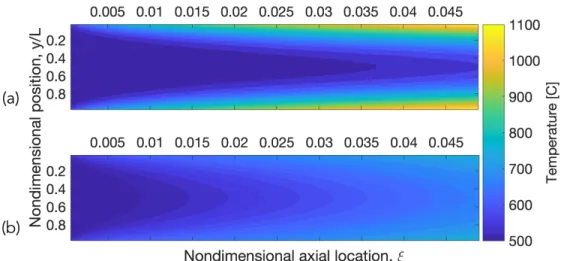
1-3 Two-dimensional axial temperature profile comparison for laminar flow between black (𝜀 = 1) plates (a) without and (b) with radiative heat transfer (𝜏 = 2, N = 0.05). . . 24
1-4 Surface-to-surface (S2S) radiation and (b) Participating media (PM) radiation 25 1-5 Diagram of radiative heat transfer applications organized by governing physics. 26 1-6 Diagram summarizing thesis research areas. . . 27
2-1 Blackbody emissive power spectrum. . . 32
2-2 Nondimensional temperature distribution with participating media radiation for a gray medium between black, isothermal plates. . . 35
2-3 Nondimensional temperature distribution with coupled radiation and conduction for a gray medium between black, isothermal plates where 𝜏𝐿 = 1 and T2/T1 = 0.5 . . . 36
2-4 Nusselt number development in heated Poiseuille flow. . . 37
3-1 Typical shape of a halide salt absorption spectrum. . . 40
3-2 Infrared absorption coefficient of several halides at room temperature. . . 41
3-3 Absorption coefficients for NaCl at A: 300K; B: 615K; C: 775K; D: 935K; and E: 1105K. Melting point is 1074K. . . 42
3-4 (a) Model, (b) concentric cuvette design, and (c) picture of the experimental apparatus for containing liquid-salt.. . . 46
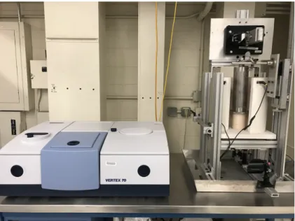
3-5 BRUKER Vertex 70 Fourier Transform Infrared (FTIR) spectroscopy experimental setup for measuring liquid-salt absorption coefficients. . . 47
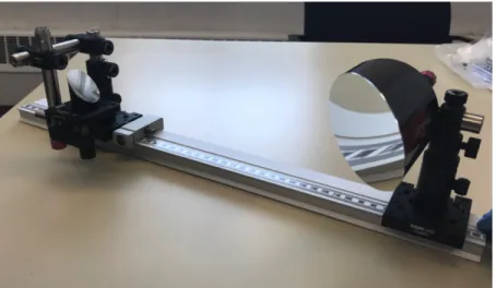
3-6 First two off-axis parabolic (OAP) mirrors with adjustable mounts used to direct light from the FTIR through the sample. . . 48
3-7 Inconel 600 cuvette design with 1" OD diamond window and grafoil seals. . . 49
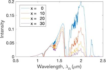
3-8 Therminol VP-1 FTIR transmission measurement data as a function of liquid attenuation thicknesses, 𝑥. . . 51
3-9 Experimental results for the attenuation coefficient of Therminol VP-1 as a function of wavelength. . . 52
3-10 Theoretical FLiNaK, FLiBe, and (Na-K)Cl absorption edges calculated by mixture-averaged weighting. . . 54
4-2 Reynolds decomposition for URANS simulation.. . . 58
4-3 Molecular Prandtl numbers of various liquid coolants as a function of temperature. . . 60
4-4 Prandtl number effects on viscous and thermal sublayers. . . 61
4-5 Kinetic and temperature spectra for liquid-salts (high Prandtl number). . . . 61
4-6 Variation of turbulent Prandtl number obtained from DNS data. . . 63
4-7 Solar spectra as a function of wavelength. . . 64
4-8 Visual representation of S2 discrete ordinates quadrature set (8 directions) . . 66
4-9 Spectral banding approximation of molecular gas bands. . . 67
4-10 DOM verification case: gray absorbing-emitting laminar flow between black (𝜀 = 1), isothermal plates. . . 68
4-11 Temperature results of laminar flow through heated plates with 𝜏𝐿 = 2 and
𝑁 = 0.05 for the (a) coarsest (Δ=1cm) and (b) finest (Δ=1.25mm) meshes. . 68
4-12 L2 norm temperature error as a function of (a) base size and (b) cell optical thickness. . . 69
4-13 Radiative and convective nondimensional heat flux comparisons where 𝜏 = 2, N = 0.05, and Δ = 1.25mm; T0/T𝑤 = 0.5. . . 70
4-14 Schematic of vertical heated pipe flow problem. . . 70
4-15 Comparison of STAR-CCM+ and COMSOL radiative heat flux at the wall as a function of axial position in vertical pipe flow. . . 71
4-16 Comparison of STAR-CCM+ and COMSOL total Nusselt number as a function of axial position in vertical pipe flow. . . 72
4-17 Wavelength ranges of energy included for inflection point method (𝑓′′(𝑥) = 0) and the selected total percentage method (95%) at T = 700∘C. . . 74
4-18 Theoretical FLiNaK absorption coefficient values at 700∘C, with and without limiters. . . 75
4-19 Comparison of one and four band Planck-mean absorption coefficients for FLiNaK at 700∘C. . . 76
4-20 Steady-state FLiNaK temperature profiles for coupled thermal radiation and conduction between 800∘C and 600∘C fixed temperature plates as a function of the number of spectral bands. . . 77
4-21 Effective power density calculations for an absorbing, emitting medium as a function of number of bands and blackbody emissive power temperature T2. . 78
4-22 Theoretical FLiNaK and FLiBe fully resolved and spectrally banded absorption coefficients at 700∘C . . . 81
5-1 Twisted elliptical tube heat exchanger tubes are investigated for use in KP-FHR design. . . 84
5-2 Twisted elliptical tube geometry and meshing. . . 85
5-3 LES results for Re = 9000 and S𝑇/d𝑚𝑎𝑥 = 1.02 showing velocity fields for
triangular array. . . 86
5-4 RANS simulation geometry and boundary conditions.. . . 87
5-5 Cross-section view of meshes used for (a) LES and (b) RANS simulations. . . 88
5-6 2D integral length scale, ℓ0, minimum values for RANS cross-section. . . 89
5-7 Radial locations in RANS geometry at L/2. . . 90
5-8 LES and RANS turbulence model velocity results at four radial locations. . . 91
5-9 LES and RANS turbulent Prandtl number temperature defect results at four radial locations. . . 92
List of Figures
5-10 Visualization of turbulent coherent structures (helicity contours with value of
1.4) using the STRUCT-𝜀 model. . . 93
5-11 Resolution of coherent structures present at radial 158∘. . . 94
5-12 STRUCT-𝜀 resolved vs. modeled turbulent fluctuations. . . 94
5-13 RANS simulation temperature defect slice at L/2.. . . 95
5-14 LES and RANS temperature defect results at four radial locations. . . 96
6-1 Proposed sizing information from for ARC first wall cooling. . . 98
6-2 Twisted elliptical tube liquid-salt-cooled geometry mesh axial cross-section. . 98
6-3 Twisted elliptical tube liquid-salt-cooled geometry and boundary conditions. . 99
6-4 Spectral banded absorption coefficient values. . . 100
6-5 Gray absorption coefficient values. . . 101
6-6 Poiseuille flow cases with 𝜏 = 5 for validation of Rosseland implementation. . 102
6-7 Radial locations at simulation outlet. . . 104
6-8 Case 1: Radial temperature defect results. . . 105
6-9 Case 2: Radial temperature defect results. . . 106
6-10 Case 3: Radial temperature defect results. . . 107
6-11 Case 4: Radial temperature defect results. . . 108
6-12 Case 5: Radial temperature defect results. . . 109
6-13 Case 6: Radial temperature defect results. . . 110
6-14 Case 7: Radial temperature defect results. . . 111
6-15 Case 8: Radial temperature defect results. . . 112
6-16 2D outlet temperature defect for Case 2. . . 113
6-17 Case 2 twisted elliptical tube wall temperature (a) without thermal radiation and (b) with spectral banded thermal radiation. . . 114
6-18 2D outlet temperature defect for Case 4. . . 114
6-19 Spectral banded result trends with Reynolds number. . . 115
6-20 Solver iteration CPU time normalized by the convection only cost. . . 116
6-21 2D outlet temperature defect for Case 4. . . 117
7-1 Twisted elliptical tube two-dimensional outlet temperature profiles (a) without and (b) with 4-banded radiative heat transfer in FLiBe (Re = 263, q𝑤” = 2.15 MW/m2). . . 122
A-1 Figures showing the shape of the FTIR beam intensity leaving the FTIR. . . 136
A-2 Results of Monte Carlo ray tracing analysis for the original mirror setup. Blue rays represent light captured by the mirror while red rays represent light that misses the mirror.. . . 136
A-3 Results of Monte Carlo ray tracing analysis for the updated mirror setup. Blue rays represent light captured by the mirror while red rays represent light that misses the mirror. . . 137
A-4 CAD image of beam reducer using two 90∘ OAPs and mounts. . . 137
B-1 Inconel 600 inner (left) and outer (right) cuvettes with perforated hole window.140 B-2 (a) Picture and (b) microscope view of Inconel 600 screen used as an optical window on the base of the cuvettes. Holes are 125𝜇m in diameter and allow light to pass through while containing the fluid by surface tension. . . 140
B-3 Experimental results for the attenuation coefficient of Therminol VP-1 as a function of wavelength for quartz and Inconel 600 cuvettes. . . 141
B-4 Hypothesized light refraction at the curved air-liquid interface. . . 141
B-5 Diamond transmission spectrum. . . 142
B-6 External, water-cooled (backwards) source strength vs. internal NIR and MIR source strengths. . . 143
B-7 External, water-cooled and standard, air-cooled MIR source spectrums.. . . . 144
B-8 MIR source spectrums using the LN-MCT vs. DLaTGS detectors with aperture sizes.. . . 144
B-9 Variable diameter outer cuvette minimizes required salt mass for absorption experiments.. . . 145
B-10 Fin analysis of Inconel 600 tubing length required to ensure liquid-salt freezing within the drain when not heated. . . 147
List of Tables
1.1 Typical reactor coolant temperatures. . . 21
1.2 Physical properties of coolants at atmospheric pressure*. . . 30
3.1 Experimental apparatus design requirements. . . 45
3.2 FTIR mid-infrared setup components. . . 47
4.1 Description of eddy-viscosity models. . . 59
4.2 Nondimensional wall heat flux percent error for 𝜏 = 2 and N = 0.05 case as a function of base size. . . 69
4.3 STAR-CCM+/COMSOL comparison simulation parameters.. . . 71
4.4 Scalar errors in vertical pipe flow between STAR-CCM+ and COMSOL results as a function of optical thickness. . . 72
4.5 Wavelength ranges inclusive of 95% of the blackbody energy as functions of temperature and lower wavelength value, 𝜆0,𝑙𝑜𝑤𝑒𝑟. . . 74
4.6 Planck-mean absorption coefficient values for FLiNaK using theoretical, spectral absorption values and blackbody radiative intensity at 700∘C. . . 76
4.7 Ratio of effective power density where T1 = 700∘C over the exact power density where T1 = T2 as a function of the number of bands and blackbody emissive power temperature T2. . . 79
4.8 Non-gray participating media thermal radiation modeling summary. . . 80
5.1 LES geometry and fluid parameters. . . 86
5.2 Summary of mesh sensitivity sizing.. . . 88
5.3 Mesh sensitivity: Normalized L2 velocity error. . . 89
5.4 Constants of NLEVM model by Baglietto and Ninokata (2006). . . 90
5.5 Summary of final RANS simulation parameters. . . 95
6.1 Geometry parameters for RANS RHT simulations. . . 99
6.2 Spectral banded absorption coefficient and optical thickness, 𝜏 , values for FLiNaK at 740∘C and FLiBe at 731∘C.. . . 100
6.3 Gray absorption coefficient and optical thickness, 𝜏 , values for FLiNaK at 740∘C and FLiBe at 731∘C. . . 100
6.4 Twisted elliptical tube CFD test matrix. . . 103
6.5 Case 1: Effective Nusselt number and maximum wall temperature error results.105
6.6 Case 2: Effective Nusselt number and maximum wall temperature error results.106
6.7 Case 3: Effective Nusselt number and maximum wall temperature error results.107
6.9 Case 5: Effective Nusselt number and maximum wall temperature error results.109
6.10 Case 6: Effective Nusselt number and maximum wall temperature error results.110
6.11 Case 7: Effective Nusselt number and maximum wall temperature error results.111
6.12 Case 8: Effective Nusselt number and maximum wall temperature error results.112
Nomenclature
Abbreviations
ARC Affordable, Robust, and Compact reactor CFD Computational Fluid Dynamics
CSP Concentrated Solar Power DNS Direct Numerical Simulation DOM Discrete ordinates method
FHR Fluoride-salt-cooled High-temperature Reactor FTIR Fourier Transform Infrared (Spectroscopy) IR Infrared
LES Large Eddy Simulation MSR Molten Salt Reactor
NLEVM Nonlinear Eddy-Viscosity Model OAP Off-Axis Parabolic (mirror)
PM Participating Media (radiation) RANS Reynolds-Averaged Navier-Stokes RHT Radiative Heat Transfer
RTE Radiative transfer equation S2S Surface-to-Surface (radiation)
URANS Unsteady Reynolds-Averaged Navier-Stokes
Symbols
𝛼 Absorptance, [-]
𝛽 Extinction coefficient, [m−1] Δ Bulk mesh resolution size, [m] ℓ Length scale, [m]
ℓ0 Integral length scale, [m] 𝜂 Kolmogorov length scale, [m] Γ Scalar quantity diffusivity 𝜅 Absorption coefficient, [m−1] 𝜆 Taylor microscale, [m] 𝜆 Wavelength, [𝜇m]
𝜇 Dynamic viscosity, [Pa·s] 𝜇𝑡 Eddy viscosity, [Pa · s] 𝜈 Kinematic viscosity, [m2/s]
𝜔 Specific turbulent dissipation rate, [s−1] 𝜅 Planck-mean absorption coefficient, [m−1]
𝜑 Scalar quantity 𝜌 Density, [kg/m3] 𝜌 Reflectance, [-] 𝜎 Stefan-Boltzmann’s constant 5.67×10⁻⁸ W/m2 · K4 𝜎𝑠 Scattering coefficient, [m−1] 𝜏 Transmittance, [-] 𝜀 Emissivity, [-]
𝜀 Turbulent dissipation rate, [m2/s3]
𝑐0 Speed of light in a vacuum 2.998×10⁸ m/s
𝑐𝑝 Specific heat, [J/kg·K] 𝐷ℎ Hydraulic diameter, 4A/P𝑤
𝐸𝑏 Blackbody emissive power, [W/m2] 𝐺 Incident radiation, [W/m2]
ℎ Planck’s constant 6.626×10⁻³⁴ J·s
𝐼 Radiative intensity, E𝑏/𝜋 𝑘 Absorption index, 𝜅𝜆/4𝜋 𝑘 Thermal conductivity, [W/m·K] 𝑘 Turbulent kinetic energy, [m2/s2] 𝑘 Wavenumber, [m−1]
𝑘𝐵 Boltzmann’s constant 1.3807×10⁻²³ J/K
𝐿𝑚 Mean beam length, 3.6V/A𝑤 𝑛 Refractive index, [-]
𝑝 Order of convergence, [-] 𝑞 Heat flux, [W/m2]
𝑄′′′ Heat production per unit volume, [W/m3] 𝑆𝑁 Ordinate sets
𝑇 Temperature, [K] 𝑡 Time, [s]
𝑇𝑑𝑒𝑓 𝑒𝑐𝑡 Temperature defect, T - T𝑎𝑣𝑔 𝑢, 𝑈 Velocity, [m/s]
𝑥 Distance or path length, [m]
𝑦+ Wall-normal distance (normalized), 𝜌𝑦𝑢𝜏/𝜇
Subscripts
0 Reference value, or in a vacuum
𝜆 At a given wavelength or per unit wavelength 𝑏 In the bulk 𝑐 Convection value 𝑟, 𝑅 Radiation value 𝑤 At the wall Dimensionless numbers 𝜏 Optical thickness, 𝜅L 𝜃 Temperature, T/T𝑟𝑒𝑓 𝜉 Axial distance, x/LRePr
𝑁 Conduction-to-radiation parameter, k𝜅/4n2𝜎T3 Pe Peclet number, RePr
Nomenclature
Pr Prandtl number, c𝑝𝜇/k
Pr𝑡 Turbulent Prandtl number, 𝜇𝑡/𝜀ℎ Re Reynolds number, 𝜌UD/𝜇
1 Introduction and Background
In recent years, the increase in non-dispatchable wind and solar electricity to the grid as well as goals to reduce CO2 emissions have changed global energy markets. There are now significant economic incentives for power generation systems that are capable of peak power production, low-cost thermal energy storage, and use in typically high carbon-emitting industrial processes such as hydrogen generation [1]. The lowest-cost technologies that meet these requirements involve high-temperature heat.
Specifically, high Prandtl number liquid-salts have become of interest to both the nuclear and solar-thermal communities [2,3]. Fluoride and chloride salts are currently being investigated for use in fluoride-salt-cooled high-temperature reactors (FHRs), molten salt reactors (MSRs), high-magnetic-field fusion machines, and concentrated solar power (CSP) systems [4–6]. While many of the specific designs have been developed over the several years, liquid-salts have been used generally as coolants for decades. Molten salt reactors were originally developed in the 1950s as part of the Aircraft Nuclear Propulsion (ANP) Program [7]. Because salt coolants have a higher average temperature of delivered heat, as shown in Table1.1, they can efficiently couple to gas turbines [8]. MSR research continued through the 1960s at ORNL with the Molten Salt Reactor Experiment (MSRE). This program led to the full power operation of an 8 MWt reactor using a LiF-BeF2-ZrF4-UF4 fuel-salt [9].
Table 1.1: Typical reactor coolant temperatures [8].
Coolant Average core inlet temperature [∘C]
Average core outlet temperature [∘C] Average temperature of delivered heat [∘C] Water 270 290 280 Sodium 450 550 500 Helium 350 750 550 Salt 600 700 650
Although the ANP and MSRE projects ended over half a century ago, their successful demonstrations have encouraged renewed investment in liquid-salt-cooled reactor concepts. On the fission side, the Mark-I pebble-bed (PB) FHR leverages improvements in advanced reactor and gas turbine technology to allow coupling of the reactor to an air Brayton combined cycle [10,11]. This enables the PB-FHR to achieve the desired base-load and peak electricity production with heat storage discussed above. On the fusion side, the affordable, robust, and compact (ARC) reactor uses high-temperature superconducting magnets to reduce the size, cost, and complexity of a fusion machine [5]. Due to it’s
(a) (b)
Figure 1-1: (a) FHR fission system (Figure reproduced from Andreades et al. [10]) and (b) ARC fusion system (Figure reproduced from Sorbom et al. [5]).
smaller size, it uses a liquid-fluoride-salt immersion blanket for heat removal, tritium breeding, and net electricity generation. The PB-FHR and ARC reactors (Figure 1-1) are now being further developed by the startup companies Kairos Power and Commonwealth Fusion Systems, respectively.
However, despite past experiments, limited experience with liquid-salt coolants leaves unanswered questions. One of the obstacles currently facing liquid-salt systems is uncertainty about their radiative heat transfer (RHT) behavior. Liquid-salt systems have typical operating temperatures above 600-700∘C and, because RHT scales as T4, thermal radiation can become a significant mechanism for heat transfer. While halide salts are generally believed to be fairly transparent, theoretical calculations show that there may be increased absorption where there is still emissive power, as shown in Figure 1-2. Nuclear salts can also contain dissolved fuel or impurities that may greatly increase the absorptivity of the salt. As a result, Phenomena Identification and Ranking Table (PIRT) exercises for FHR and MSR thermal-hydraulics have identified salt infrared (IR) absorption as an area needing further study [12,13].
In this thesis, we explore the challenges of predicting radiative heat transfer in high-temperature liquid-salts. We begin with a review past experimental and computational efforts to identify areas where additional research is needed. We then discuss the development and implementation of a methodology that addresses current gaps and enhances RHT modeling accuracy and usability. This analysis focuses on fluoride and chloride salt eutectics as these are of the most interest to nuclear systems.
1.1
Motivation for Radiative Heat Transfer Modeling
Three-dimensional RHT modeling within a fluid medium has been used for many years to design combustion systems such as industrial furnaces and internal combustion engines [16–18]. However, accounting for coolant-thermal radiation interaction is less common in
1.1. Motivation for Radiative Heat Transfer Modeling
Figure 1-2: Blackbody emission spectrum and theoretical pure NaCl-KCl, FLiNaK, and FLiBe absorption coefficients at 700∘C. Theoretical values were obtained using a component salt mixture-averaging method developed by Chaleff et al. [14] and data from Li [15].
the nuclear industry. Light-water reactors run near 300∘C where the RHT contribution is very low. FHRs and MSRs, on the other hand, operate with an absorbing coolant near 700∘C where the radiative power is roughly ten times greater (and can reach up to 1000∘C where it would be ∼25 times greater).
In liquid-salt systems, radiative heat transfer can lead to:
- Decreased surface temperatures, especially in off-nominal or accident conditions - Increased temperature uniformity within the coolant
- Improved passive heat rejection at high temperatures while avoiding overcooling and salt freezing [19]
Due to the highly coupled nature of reactor systems, changes in heat transfer and temperature predictions can have cascading effects across reactor design. Corrosion behavior, for example, is strongly dependent on temperature, so accurate thermal modeling is essential to predicting material performance. Studies of Hastelloy-N in molten uranium fluorides have observed that a 100∘C rise in temperature increases the equilibrium mole fraction of CrF2 by an order of magnitude [20]. This change in solubility is the main driving force for observed corrosion mass transfer from hot to cold regions. In CSP systems, wind loads and vibrations can have large impacts on local hot spots and greatly increase the number of observed thermal cycles and structural fatigue [21]. The design of passive safety systems can also be affected. Cooling that relies on natural circulation may see decreased efficiency and lower flow rates due to RHT energy redistribution.
To visualize the effects of RHT, a representative simulation was run with and without thermal radiation. Because RHT effects are strongest in areas of reduced mixing and FHRs
operate in the laminar to transitional flow regime [14,22], a test case modeling a gray, absorbing and emitting fluid (Prandtl = 1.6) in fully developed Poiseulle flow (Reynolds = 500) was selected [23]. Constant heat flux and inlet temperature boundary conditions of 30 kW/m2 and 500∘C, respectively, were applied. The results of these simulations are shown in Figure1-3.
Figure 1-3: Two-dimensional axial temperature profile comparison for laminar flow between black (𝜀 = 1) plates (a) without and (b) with radiative heat transfer (𝜏 = 2, N = 0.05).
For these parameters, modeling thermal radiation lowers the wall temperature by as much as 370∘C for the same heat flux. Additionally, thermal radiation improves heat transfer into the bulk fluid and increases temperature uniformity. For this gray, two-dimensional test case, the RHT modeling implementation is fairly straightforward. However, accounting for thermal radiation in real systems is considerably more challenging.
1.1.1 State-of-the-Art Modeling and Limitations
Coupling thermal radiation with conduction or convection results in highly nonlinear integro-differential equations. Exact analytical solutions to these equations are only possible for the simplest cases which are of little, practical engineering value. To be useful, RHT contributions need to be solved in complex, three-dimensional flows which requires numerical solution methods. In the nuclear industry, there is already a strong push to move from modeling reactors with system thermal hydraulics codes to using Computational Fluid Dynamics (CFD). Advances in computational power now allow for high-fidelity, three-dimensional modeling of velocity and temperature profiles that can lead to reduced uncertainty and enhanced safety [24]. CFD may be an especially valuable tool for non-LWR design and licensing where current system codes are not yet well calibrated, empirical correlations may not exist, and where higher temperatures drive the need for accurate local temperature predictions.
CFD codes are capable of solving coupled, nonlinear equations such as the radiative transfer equation. Unfortunately, there has been limited work done on resolving the complex, even by thermal radiation standards, physics in liquid-salt systems. Most CFD RHT applications
1.1. Motivation for Radiative Heat Transfer Modeling
focus on only surface-to-surface (S2S) radiation, or radiative exchange between walls where the medium does not participate. Some of the biggest users of thermal radiation modeling CFD are the aerospace, automotive, and solar energy industries which are driven by S2S radiation. Even nuclear applications such as heat transfer in high-temperature gas-cooled reactor (HTGR) cores model thermal radiation between pebbles as surface-to-surface [25].
(a) (b)
Figure 1-4: (a) Surface-to-surface (S2S) radiation and (b) Participating media (PM) radiation.
Problems involving high-temperature liquid-salts require solving the radiative transfer equation for a participating media (PM) because the salt itself will absorb and emit thermal radiation (Figure 1-4). In participating fluids, it is important to understand how RHT will contribute to the overall energy transfer due to the coupled nature of temperature and velocity solutions. Fully integrated heat transfer modeling can be required to ensure solution accuracy. The state-of-the-art tool for this is the discrete ordinates method (DOM) because it generally provides a good balance between flexibility, accuracy, and computational cost [26–28]. While, DOM has proven readily usable in many participating radiation focused industries (e.g. combustion systems [29,30]), liquid-salt systems encounter three, additional modeling challenges.
First, liquid-salts have refractive indices, 𝑛, greater than 1. In combustion systems where most PM modeling is done, 𝑛 is equal to 1, so much of the literature and some CFD codes neglect 𝑛 dependencies in governing equations. Because the refractive index in fluoride salts is near 1.3 [31] and thermal radiation scales with 𝑛2, using a value of 1 would underestimate radiative emissions in FHRs by almost 70%.
Second, most participating media simulations assume the continua are gray, which is defined as having an absorption coefficient, 𝜅, that is constant across all wavelengths. As can been seen from Figure 1-2, this is a poor assumption for liquid-salt absorption behavior. Halide salt absorption coefficients can change by orders of magnitude over small wavelength ranges [15], acting as non-gray media. While it is possible to model liquid-salts as gray, their strong absorption in the mid-IR can skew averages to very large values. However, while DOM has reasonable computational requirements for gray media, attempting to fully resolve the absorption spectrum would be prohibitively expensive.
Third, although it is known generally that liquid-salts are non-gray, the spectral absorption coefficient curves of the salt eutectics discussed here are not yet known. There is little to no experimental data that quantifies their optical properties. Even their more commonly used
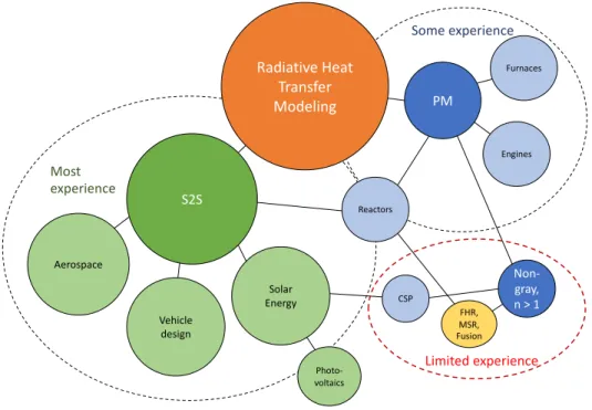
Aerospace S2S Vehicle design PM Solar Energy Engines Furnaces Non-gray, n > 1 FHR, MSR, Fusion Photo-voltaics CSP Radiative Heat Transfer Modeling Most experience Some experience Limited experience Reactors
Figure 1-5: Diagram of radiative heat transfer applications organized by governing physics.
thermophysical properties such as viscosity and thermal conductivity have uncertainities up to 20% [32]. This is in large part due to the significant challenges of running high-temperature liquid-salt experiments. Strict thermal, chemical, and optical requirements all contribute to apparatus complexity and cost. While theoretical values obtained by density functional theory and ab initio molecular dynamics [33], or weighting of constituent salt absorption coefficients are useful due to the challenge natural of high-temperature liquid-salt handling, experimental measurements of real liquid-salts are desired for validation.
The discussed limitations serve as the motivation for this work.
1.1.2 Objectives and Outcomes
This thesis aims at achieving four main research goals to advance modeling in high-temperature liquid-salt systems (reference Figure 1-6):
1. Quantification of fundamental fluoride and chloride liquid-salt spectral absorption properties
2. Formulation of a high-fidelity CFD-DOM methodology to capture spectral effects at reasonable computational cost
3. Computational analysis of RHT contributions in a flow geometry of interest to FHRs 4. Implementation of a simplified RHT modeling approach and determination of best
1.1. Motivation for Radiative Heat Transfer Modeling
1
Carolyn Coyle | PhD Defense
FTIR spectroscopy experimental apparatus
1. Thermal radiation
property measurements CFD-DOM spectral banding
methodology
2. RHT model development
Twisted elliptical tube test case
3. Computational analysis
Compare spectral banded, gray, and Rosseland RHT model results
4. Determination of RHT modeling best practices
Kairos Power FHR Design
Figure 1-6: Diagram summarizing thesis research areas (Figure modified from Kairos Power [34]).
Outcomes of this work may include more effective and accurate design of high-temperature components and increased safety margins in reactor licensing. These can contribute to the near-term deployment of Generation-IV liquid-salt reactors. While this work was developed for liquid-salt reactors, the methodology can be adapted to a variety of heat transfer systems.
1.1.3 Thesis Organization
Chapter2provides a review of fundamental radiative heat transfer behavior with emphasis on participating media physics. Governing dimensionless numbers are defined and solutions for simple, participating media test cases coupled with conduction and convection are shown. Chapter3details the design and verification of an experimental apparatus built to measure high-temperature halide salt optical properties. The main focus of this chapter is to discuss how the final system design is driven by functional requirements. Experimental methods including experimental procedures, data analysis, and measurement verification are also detailed. Future steps needed to complete fluoride and chloride measurements are outlined. Chapter 4 moves into computational modeling and proposes a new methodology to solve for RHT in non-gray, participating media using spectral banding. This method aims at reducing computational cost while still capturing spectral effects.
Chapter 5 then applies the new methodology to a twisted elliptical tube heat exchanger test case. Initial RANS simulations without RHT are validated against large eddy simulation (LES) results.
Chapter 6 provides an analysis of modeling participating media radiation in real systems. Simulations are run with theoretical FLiNaK and FLiBe properties to quantity RHT contributions to the overall heat transfer. Less computationally expensive methods with lower accuracy are tested and compared against spectral banded results. This information is used to identify the limitations of each method and derive best practices for RHT modeling applications.
Chapter7concludes this work and details research findings and contributions. Future work is also identified and discussed.
1.2
High-Temperature Liquid-Salt Background
This section gives additional, contextual information on high-temperature liquid-salts. This includes a review of specific energy generation technologies as well as thermophysical property requirements and classes of salts being considered.
1.2.1 Power Generation Applications
As already discussed, high-temperature liquid-salts are being utilized in advanced power systems for both near-term (e.g. FHRs, CSP) and long-term (e.g. fusion) deployment. Several of these designs are described below.
Fluoride-Salt-Cooled High-Temperature Reactors: FHRs are considered a competitive option for near-term deployment because they leverage existing technologies. They utilize a solid graphite-matrix fuel design similar to those in HTGRs, but with a liquid-salt coolant used in place of a gas [3]. 2LiF - BeF2 (FLiBe) and NaF-ZrF4 (Nafzirf) are the main candidates for the primary loop coolant while LiF-NaF-KF (FLiNaK) is a likely choice for the secondary loop [32]. Safety systems are able to build on those designed for sodium fast reactors as both are low-pressure, liquid-cooled systems.
Molten-Salt Reactors: In MSR designs, fuel and fission products are dissolved directly into the liquid-salt coolant and flow through the primary loop [35]. Fission takes place in the reactor core where neutrons are moderated by exposed graphite. MSR salts require high solubility for specific actinides to ensure required fertile and fissile materials remain in solution [36]. Salt selection is determined by the actinides of interest and desired neutron spectrum. FLiBe is a popular choice for the coolant base due to its successful use in the Molten Salt Reactor Experiment (MSRE).
Molten-Salt Fast Reactors: MSFRs are attractive because of their breed-and-burn capabilities, allowing them to use depleted fuel and achieve higher burnup. This reactor benefits from advancements in sodium fast reactor pool design. MSFRs typically use chloride salt coolants because chlorides are less effective than fluorides at thermalizing neutrons.
High-Field Fusion Reactors: Compact, high-field fusion machines have been made possible with the introduction of high-temperature superconducting magnets. These magnets are
1.2. High-Temperature Liquid-Salt Background
capable of sustaining large, on-axis magnetic fields which significantly reduce the size and cost of the reactor [5]. With the increased power density, a liquid FLiBe immersion blanket is needed to provide the necessary cooling as well as neutron shielding and tritium production. Additionally, the properties that benefit FLiBe in fission reactors also make it well suited for use in fusion systems.
Concentrated Solar Power: CSP systems use integrated thermal energy storage to solve the solar power intermittency problem. An array of heliostats direct sunlight into focused beams that heat the liquid-salt. This heated salt is then stored in large hot and cold tanks to be charged and discharged for electricity generation as needed [6,37]. Recently, the CSPonD project developed an innovative, single tank system in collaboration with MIT to further reduce cost [38]. The most common choice for the working fluid in CSP systems is a nitrate salt. Parabolic trough solar collectors are similar systems that direct solar energy onto tubes containing a flowing, working fluid rather than into a tank.
1.2.2 Candidate Salt Selection
Liquid-salts have several key properties that make them well suited for use in high-temperature reactors [39,40]. First, they have large operating temperature ranges. Second, liquid-salts have relatively low vapor pressures to allow for use at or near ambient pressure. And third, they have large volumetric heat capacities to achieve efficient cooling and maintain safety margins in accident scenarios. Generally, these liquid-salts to can be classified into three categories based on anion composition: nitrates, fluorides, and chlorides. The salts in each of these categories tend to have similar properties that determine their functionality.
Nitrate salts have been used historically for thermal energy storage in CSP systems. The most common choice is a 60 wt.% NaNO3 : 40 wt.% KNO3 binary nitrate or “solar salt” due to its strong solar radiation absorption and low cost. However, nitrate salts begin to decompose near 600∘C, so they have limited use in nuclear systems. For higher temperature applications, halide salts are good candidates.
Fluoride salts have been the main focus of Generation-IV salt reactor research due to their chemical stability, relatively non-corrosive behavior, low neutron cross sections, and successful use in test nuclear systems [35]. Sodium and aluminum fluorides have been used by the chemical industry for over a century to manufacture aluminum which provides significant industrial experience to draw from. Fluorides also have high uranium and thorium solubility which optimizes them for use in dissolved-fuel reactors [40]. In fusion machines, lithium is enriched to 6Li to maximize tritium production. In fission systems, 7Li is preferred to reduce tritium production [8].
Chloride salts are the other commonly used halide coolant with applications in energy generation. In nuclear systems, chlorides are better tailored for use in MSFRs. They have the lower neutron moderation and higher actinide solubility required to maintain criticality as fission products are created [41]. Chlorides also have larger thermal neutron absorption cross sections which make them poor coolants for thermal reactors, but are acceptable for fast reactors. 37Cl is used to achieve the higher breeding ratios that enable breed-and-burn
reactor operation [42]. In advanced CSP systems, sodium-potassium-magnesium chlorides are being researched as high-temperature alternatives to solar salt [43]. These chloride salts operate near 700-750∘C where radiative heat transport becomes important.
1.2.3 Thermophysical Properties
Much of the existing data for fluoride salts was generated during the ANP and MSRE programs at ORNL in the 1950s and 60s. Research included areas such as material compatibility, physical property quantification, heat transfer characteristics, and salt manufacturing, purification, and handling [44]. Since that time, several literature reviews have been conducted along with limited, additional testing. Recently, molecular dynamics simulations have been used to estimate salt properties because of the difficulty in running high-temperature salt experiments [32,33]. Table 1.2[31,32,45,46] includes some relevant thermophysical properties of candidate fluoride and chloride salts as well as nitrate “solar salt” and saturated water data for comparison.
Table 1.2: Physical properties of coolants at atmospheric pressure*. Coolant T𝑚𝑒𝑙𝑡 (∘C) T𝑏𝑜𝑖𝑙 (∘C) 𝜌 (︁𝑚𝑘𝑔3 )︁ k (︀ 𝑊 𝑚·𝐾 )︀ 𝐶𝑝 (︁ 𝐽 𝑘𝑔·𝐾 )︁ LiF-NaF-KF (46.5-11.5-42 mol%) 454 1570 1972 0.9 1884 LiF-BeF2 (66-34 mol%) 459 1430 1940 1.0 2386 NaF-ZrF4 (59.5-40.5 mol%) 500 1350 3140 0.49 1172 KCl-MgCl2 (68-32 mol%) 425 1418 1514 0.44 1013 NaNO3-KNO3 (60-40 wt%) 221 ∼620 1745 0.55 1537 H20 (at 7.5MPa) 0 290 732 0.56 5520
*Fluoride and chloride salt properties are given at 700∘C while nitrate salt data is given at 550∘C. Pressurized water data given at saturation for comparison.
2 Fundamentals of Radiative Heat Transfer
Here, we provide a brief overview of radiative heat transfer theory and discuss the principles and equations relevant to this work. For a more detailed explanation, we suggest the textbook Radiative Heat Transfer by Modest [26].
2.1
Physics of Thermal Radiation
Radiative heat transfer is energy transferred through electromagnetic waves (i.e. through moving photons). The amount of energy emitted by an object depends on its temperature and surface characteristics. A blackbody, or an ideal surface that absorbs all radiation and emits the maximum energy possible at a given temperature, emits according to the Stefan-Boltzmann law, defined in Eq. 2.1[47]:
𝐸𝑏 = 𝑛2𝜎𝑇4 (2.1)
where 𝐸𝑏 is the blackbody emissive power, 𝑛 is the refractive index, 𝑇 is the absolute temperature, and 𝜎 is the Stefan-Boltzmann constant. The emissive power is defined as the radiative heat flux emitted from a surface. As can be seen, thermal radiation is strongly dependent on temperature which explains why it can become a dominating heat transfer term in high-temperature applications.
The total blackbody emissive power of an object is distributed over all wavelengths. The shape of this distribution is defined by Planck’s law (Eq. 2.2):
𝐸𝑏𝜆=
2𝜋ℎ𝑐20
𝑛2𝜆5[𝑒ℎ𝑐0/𝑛𝜆𝑘𝐵𝑇 − 1] (2.2) where 𝐸𝑏𝜆 is the spectral blackbody emissive power, ℎ is Planck’s constant, 𝑐0 is the speed of light, 𝜆 is the wavelength, and 𝑘𝐵 is the Boltzmann’s constant. Figure 2-1 plots the blackbody emissive power spectrum for several temperatures and refractive indices. Significant trends are that as temperature increases, the total level of emissions increases (consistent with Eq. 2.1) and the emission spectrum peak shifts to lower wavelengths. Similarly, for a given temperature, an increase in refractive index will increase total emissions and push the peak to the left. These plots are especially helpful in determining the wavelength regions where RHT will be strongest for a given problem.
Figure 2-1: Blackbody emissive power spectrum.
blackbody). Photons at every wavelength can be either reflected at the surface, absorbed in the bulk, or transmitted through the material, as defined by Eq.2.3:
𝜌𝜆+ 𝛼𝜆+ 𝜏𝜆 = 1 (2.3)
where 𝜌𝜆, 𝛼𝜆, and 𝜏𝜆 are the spectral reflectance, absorptance, and transmittance, respectively. Additionally, a real body will only emit a fraction of the total blackbody emissive power. The ratio of the energy emitted from the surface to the energy emitted by a black body at the same temperature is defined as the emissivity, 𝜀. Similarly to the emissive power, emissivity can also vary spectrally (𝜀𝜆). Media where 𝜀𝜆 is constant across all wavelengths are called gray while media where 𝜀𝜆 varies are called non-gray. A non-gray 𝜀𝜆 can be weighted by the spectral blackbody emissive power to calculate an effective gray emissivity or Planck-mean emissivity value for a given wavelength range according to Eq. 2.4. 𝜀 = ∫︀𝑏 𝑎𝜀𝜆𝐸𝑏𝜆𝑑𝜆 ∫︀𝑏 𝑎𝐸𝑏𝜆𝑑𝜆 (2.4)
The value of 𝜀 varies between 0 and 1, where 1 would be a perfect absorber and 0 would be a perfect reflector.
As a consequence of the Second Law of Thermodynamics, 𝜀𝜆 and 𝛼𝜆 can be equated using Kirchhoff’s law (Eq. 2.5):
𝜀𝜆= 𝛼𝜆 (2.5)
which states that, for a diffuse body, an object must emit as much energy as it can absorb at each wavelength at a given temperature. This means that knowing how an object absorbs radiation also defines how it will emit.
2.2. Radiation Behavior in Participating Media
2.2
Radiation Behavior in Participating Media
As discussed above, thermal radiation can be absorbed and emitted by surfaces, but it is also possible for this energy to interact within a medium and be absorbed gradually. In many cases, such as in air or over short distances, these interactions can be neglected and RHT is defined only by surface-to-surface (S2S) energy transfer. But at high temperatures (i.e. combustion gases, molten salts) or over long distances (i.e. the atmosphere), RHT will occur within the medium itself. These cases are defined as participating media or semitransparent media.
Radiation exchange in participating media depends on the radiative properties and geometry of the surfaces, but also on the temperature-dependent, radiative properties of the fluid [26, 48]. Radiation traveling through a participating medium may be transmitted, attenuated, or re-emitted. The spectral transmittance of the medium is defined by Eq.2.6.
𝜏𝜆 = 𝐼𝜆(𝑥) 𝐼𝜆(0)
= 𝑒−𝛽𝜆𝑥 (2.6)
This exponential decay is commonly referred to as Beer’s law, where 𝛽𝜆 is the spectral extinction or attenuation coefficient and 𝑥 is the attenuation distance. The extinction coefficient combines the effects of absorption, 𝜅, and scattering, 𝜎𝑠, within the medium, as shown in Eq.2.7:
𝛽𝜆 = 𝜅𝜆+ 𝜎𝑠𝜆 (2.7)
Past research has found scattering in liquid-salts to be negligible [49,50]. So for this discussion, we will assume zero scattering (𝛽𝜆 = 𝜅𝜆).
The absorption coefficient and attenuation distance can be multiplied to form a dimensionless variable called the optical thickness, 𝜏𝜆 (Eq.2.8).
𝜏𝜆 = 𝜅𝜆𝑥 (2.8)
It is useful to analyze semitransparent problems in terms of 𝜏𝜆 because it provides intuition into how RHT will behave in any size geometry. If 𝜏𝜆 << 1, called “optically thin", the thermal radiation will not be significantly attenuated before it reaches the next surface, so the problem will greater resemble surface-to-surface radiation. Oppositely, if 𝜏𝜆 >> 1, called “optically thick", radiation will be absorbed and emitted over such small distances that the effects of RHT can be treated as an overall increase in thermal conductivity of the medium [51]. When the optical thickness is close to 1, the effects of participating media are most interesting and RHT can become an excellent mechanism for energy redistribution.
Again, it is important to remember that geometry alone is not enough to understand whether a fluid will act as a participating media. One needs to consider both the attenuation distance and the absorption coefficient (i.e. optical thickness, 𝜏 ).
2.3
Coupled Participating Media Solutions
Thermal radiation is only one mode of heat transfer, and generally must be solved together with conduction and convection. The general form of the energy conservation equation (Eq 2.9) for a moving, incompressible fluid can be used to solve for the total temperature field: 𝜌𝑐𝑝 (︂ 𝜕𝑇 𝜕𝑡 + 𝑢 · ∇𝑇 )︂ = ∇ · (𝑘∇𝑇 ) + 𝑄′′′− ∇ · 𝑞𝑅 (2.9) where 𝑢 is the velocity vector, 𝑄′′′is the internal heat generation, and 𝑞𝑅is the radiative heat flux vector. To solve for the radiative heat flux, we define the radiative transfer equation (RTE), given in Eq. 2.10, which describes the change in radiative energy along a path due to absorption, emission, and scattering:
𝑑𝐼𝜆 𝑑𝑠 = 𝜅⏟ ⏞ 𝜆𝐼𝑏𝜆 emission − 𝜅𝜆𝐼𝜆 ⏟ ⏞ absorption − 𝜎𝑠𝜆𝐼𝜆 ⏟ ⏞ out-scattering +𝜎𝑠𝜆 4𝜋 ∫︁ 4𝜋 𝐼𝜆( ^𝑠𝑖)Φ𝜆( ^𝑠𝑖, ^𝑠)𝑑Ω𝑖 ⏟ ⏞ in-scattering (2.10)
The main takeaway here is that solving this equation is challenging. It is an integro-differential equation for radiative intensity, 𝐼𝜆, in five independent variables (three space and two direction coordinates). 𝐼𝜆 is defined in Eq. 2.11 and Φ is the scattering phase function that describes in-scatter probabilities. Radiative intensity is used because, unlike emissive power, it is capable of capturing directional dependencies in the radiation field.
𝐼𝑏𝜆(𝑟, 𝜆) = 𝐸𝑏𝜆(𝑟, 𝜆)/𝜋 (2.11)
For liquid-salt applications, we use a zero-scattering assumption (𝜎𝑠 = 0) as discussed above. This leads to the radiative heat transfer equation for an absorbing-emitting medium (Eq.2.12):
𝑑𝐼𝜆
𝑑𝑠 = 𝜅𝜆𝐼𝑏𝜆− 𝜅𝜆𝐼𝜆 (2.12)
where the first term is the intensity gain due to emission and the second term is the intensity loss due to absorption. This equation governs the radiative physics relevant to this thesis.
In the remainder of this chapter, simplified gray, non-scattering, one- and two-dimensional geometries are used to observe heat transfer trends in (1) participating media, (2) participating media coupled to conduction, and (3) participating media coupled to convection. All problems are at steady state and must be solved for by numerical or approximation methods.
2.3.1 Participating Media between Black Plates
We begin with a one-dimensional case modeling gray media between black (𝜀 = 1), isothermal plates. Through substitutions and simplifications, the integral equation
2.3. Coupled Participating Media Solutions
governing the temperature distribution becomes:
Φ𝑏(𝜏 ) = 1 2 [︂ 𝐸2(𝜏 ) + ∫︁ 𝜏𝐿 0 Φ𝑏(𝜏′)𝐸1( ⃒ ⃒𝜏 − 𝜏′⃒⃒)𝑑𝜏′ ]︂ (2.13)
where 𝐸𝑛(𝑥) is an exponential integral, Φ𝑏 is the non-dimensional temperature (Eq.2.14), and 𝜏 is the optical thickness.
Φ𝑏(𝜏 ) = 𝑇4− 𝑇4 2 𝑇14− 𝑇4 2 (2.14)
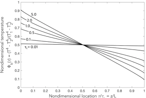
Equation 2.13 is called a Fredholm integral equation and was first solved numerically by Heaslet and Warming [52]. Figure 2-2 shows the resulting nondimensional temperature profiles for a range of optical thicknesses.
Figure 2-2: Nondimensional temperature distribution with participating media radiation for a gray medium between black, isothermal plates.
Important trends are that as 𝜏𝐿 approaches 0, the problem becomes optically thin and the solution looks like S2S radiation. Conversely, as 𝜏𝐿 becomes larger than 1 (optically thick), the solution approaches the conduction, or enhanced effective thermal conductivity solution, as discussed in Section 2.2. Notice there can also be temperature discontinuities at the boundaries when there is no conduction or convection present.
2.3.2 Participating Media with Conduction between Black Plates
The energy equation for a non-dimensional, planar medium with coupled conduction and participating media radiation without internal heat generation is given in Eq.2.15:
𝑑 𝑑𝑧 (︂ 𝑘𝑑𝑇 𝑑𝑧 − 𝑞𝑅 )︂ = 0 (2.15)
By introducing the following nondimensional variables: 𝜃 = 𝑇 𝑇1 , 𝜏 = 𝜅𝐿, Ψ𝑅= 𝑞𝑅 𝑛2𝜎𝑇4 1 , 𝑁 = 𝑘𝜅 4𝑛2𝜎𝑇3 1 (2.16)
where 𝑘 is the thermal conductivity, Eq. 2.15reduces to Eq. 2.17[26]: 𝑑2𝜃 𝑑𝜏2 = 1 4𝑁 𝑑Ψ𝑅 𝑑𝜏 (2.17)
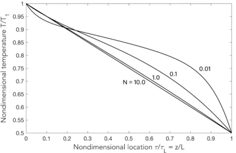
This equation can be solved numerically using a finite-differencing scheme. The nondimensional temperature distribution for a case with constant temperature boundary conditions is shown in Figure 2-3. This exercise demonstrates the importance of the nondimensional number 𝑁 , called the conduction-to-radiation parameter, which describes the relative power of conduction heat transfer compared to RHT. For 𝑁 >1, conduction dominates while for 𝑁 <1, radiation dominates. This can be observed in the flattening of temperature distributions as 𝑁 decreases.
Figure 2-3: Nondimensional temperature distribution with coupled radiation and conduction for a gray medium between black, isothermal plates where 𝜏𝐿 = 1 and T2/T1 = 0.5
2.3.3 Participating Media with Convection between Black Plates
The final case explored here is for fully developed laminar flow between two isothermal, black plates. The velocity profile for this laminar, or Poiseuille, flow is given in Eq.2.18:
𝑢(𝑦) = 6𝑢𝑚 𝑦 𝐿 (︁ 1 − 𝑦 𝐿 )︁ , 𝑣 = 0 (2.18)
where 𝑢𝑚 is the mean velocity, 𝑦 is the transverse distance, and 𝐿 is the distance between plates. Including the following dimensionless variables to those defined in the previous
2.3. Coupled Participating Media Solutions section: 𝜂 = 𝑦 𝐿, 𝜉 = 𝑥 𝐿𝑅𝑒𝑃 𝑟 (2.19)
where 𝑥 is the flow distance, 𝑅𝑒 is the Reynolds number, and 𝑃 𝑟 is the Prandtl number, the energy equation becomes (2.20):
6𝜂(1 − 𝜂)𝜕𝜃 𝜕𝜉 = 𝜕2𝜃 𝜕𝜂2 − 𝜏𝐿 4𝑁 𝑑Ψ𝑅 𝑑𝜂 (2.20)
This Poiseuille flow problem was first solved by Kurosaki [53] and later by Chawla [54]. Temperature and radiative flux profiles are obtained using implicit numerical methods. This requires iterating on an initial guess of the temperature field until convergence criteria are met. Figure 2-4 shows the axial development of the mean Nusselt number, defined in Eq. 2.21: 𝑁 𝑢𝑚(𝜉) = 1 2𝜉 ln (︂ 1 − 𝜃0 1 − 𝜃𝑚 )︂ (2.21) where 𝜃0 and 𝜃𝑚 are the nondimensional initial and bulk temperatures, respectively.
Figure 2-4: Nusselt number development in heated Poiseuille flow.
Due to the nonlinear radiative component, a fully developed temperature profile, and therefore a converged Nusselt number, cannot develop [26]. Instead, the mean Nusselt number initially decreases as the convective contribution reduces and then begins to increase as the relative radiative contribution starts to dominate. This physics drives the observed increase in mean Nusselt number and movement of the inflection point upstream as the relative thermal radiation contribution increases (increase in 𝜏 , decrease in 𝑁 ). This geometry is used in the following chapter for verification of CFD DOM solvers.
3 Optical
Property
Measurement
Apparatus Design and Validation
High-quality spectral optical property data is needed to enable accurate radiative heat transfer temperature predictions in high-temperature systems such as FHRs. In this chapter, we present the design of an experimental apparatus capable of precise absorption coefficient measurements over a wide range of values in the near- to mid-IR spectrum (2-14 𝜇m). This apparatus was designed to measure 46.5 mol% LiF: 11.5 mol% NaF: 42 mol% KF fluoride and 50 wt% NaCl:50 wt. % KCl chloride salt eutectics throughout their temperature operating range (550-1000∘C).
Halide salt absorption theory and previous work are discussed in Sections 3.1 and 3.2. The apparatus design criteria such as chemical, optical, and temperature compatibility and final experimental setup are presented in Section 3.3. Finally, apparatus validation and uncertainty analyses are shown in Section 3.4. Due to unforeseen delays and closures as a result of the COVID-19 pandemic, experimental measurements of FLiNaK and (Na-K)Cl salts were not completed. Final steps for completing these experiments are outlined at the end of this chapter and theoretical values to be used moving forward are defined.
3.1
Radiation Absorption Theory in Halide Salts
To understand how factors such as salt composition and temperature will affect absorption properties, it is necessary to explore the physics of semitransparent, halide absorption. Absorption in ionic solids and liquids can be well explained by the Lorentz model of electron/ion harmonic oscillators which can be used to identity three main regions that dominate the optical absorption of a material: 1) a high energy Urbach absorption region, 2) a low energy, multiphonon absorption region, and 3) a highly transmissive region (Figure 3-1) [15,26,55].
3.1.1 Urbach Absorption
At high energies, and therefore short-wavelengths, radiation can be absorbed by exciting valence band electrons across the band gap into the conduction band (electronic absorption). This increase in absorption coefficient is defined as Urbach absorption edge or
Figure 3-1: Typical shape of a halide salt absorption spectrum.
the short-wavelength absorption edge, as this generally occurs in the ultraviolet and visible wavelengths.
3.1.2 Multiphonon Absorption
At lower energies (long-wavelengths), halide salts can absorption thermal radiation through multiphonon absorption or photon excitation of lattice vibrations (vibrational absorption). Essentially, when an incoming photon has an energy corresponding to normal vibrational mode, the photon can be completely absorbed within the material, converting the energy to heat. This occurs at the Reststrahlen band edge, also called the long-wavelength absorption edge, in the mid-infrared region. Figure 3-2 shows the absorption coefficients for several halide salts at room temperature.
3.1.3 Transmissive Region
Halides are generally highly transmissive between these Urbach and Multiphonon absorption edges. There are many applications for halide salts that take advantage of this low absorption behavior in the visible to near-infrared wavelengths (e.g. Calcium fluoride (CaF2) is often used as a window material for spectroscopy, semiconductor processing, and cooled thermal imaging applications [56]). In this region, increased absorption is often a result of localized lattice defects, dopants, or material impurities.
This work is most concerned with the location of the multiphonon absorption edge for candidate halide salts. Because the thermal radiation is dominated by absorption and emission of bodies between 550-1000∘C, the wavelength region of interest is 1-15 𝜇m (reference Figure 2-1), which includes the multiphonon absorption edge.
3.1. Radiation Absorption Theory in Halide Salts
Figure 3-2: Infrared absorption coefficient of several halides at room temperature (Figure reproduced from Smakula [55]).
While studying the multiphonon absorption edge, there are two important trends to consider: 1) the effect of halide salt composition and 2) the effect of temperature. According to the Szigeti relation for a linear diatomic molecule, the fundamental vibrational frequency is inversely proportional to the reduced mass. Therefore, as can be seen in Figure3-2, heavier molecules (i.e. larger cation or anion) will push their multiphonon absorption edge to larger wavelengths. For example, in FLiNaK, the order that the absorption edges will appear, from smallest to largest wavelength, is LiF, NaF, then KF. Additionally, the absorption edge of salt eutectics is often dominated by the lightest molecule, so FLiNaK’s absorption edge will most likely be strongly related to that of LiF.
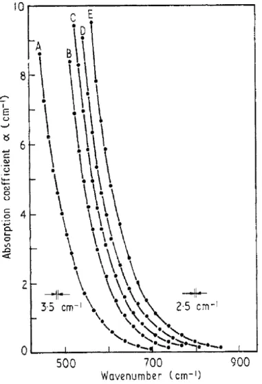
The multiphonon absorption edge will also shift with temperature. As temperature increases, the Reststrahlen bands tends to broaden which pushes the absorption edge to short wavelengths. Barker [57] studied the effects of increasing temperatures on KBr, NaCl (shown in Figure 3-3), and LiF and found a predictable shift in the absorption coefficient when accounting for density changes, even across the melting point.
Figure 3-3: Absorption coefficients for NaCl at A: 300K; B: 615K; C: 775K; D: 935K; and E: 1105K. Melting point is 1074K (Figure reproduced from Barker [57]).
3.2
Previous Work
3.2.1 Theoretical Calculations
Due to the difficulty in performing high-temperature measurements of corrosive liquids, a significant portion liquid-salt optical properties research has focused on theoretical calculations. The ability to quantify physical properties over a wide range of conditions is highly valuable. Density functional theory (DFT) and ab initio molecular dynamics (AIMD) are commonly used tools used for property, structure, and chemistry predictions. These can include thermophysical properties, transport properties, as well as radiative absorption coefficients.
![Figure 3-2: Infrared absorption coefficient of several halides at room temperature (Figure reproduced from Smakula [55]).](https://thumb-eu.123doks.com/thumbv2/123doknet/13890299.447332/41.918.200.715.117.552/figure-infrared-absorption-coefficient-halides-temperature-reproduced-smakula.webp)