Design and Testing of a Flexible Exoskeleton-to-Shoe Interface
by Dalia Leibowitz
Submitted to the
Department of Mechanical Engineering
in Partial Fulfillment of the Requirements for the Degree of Bachelor of Science in Mechanical Engineering
at the
Massachusetts Institute of Technology
June 2016 MASSACHUSETTS INSTITUTE OF TECHNOLOGY
JUL
0 8
2015
LIBRARIES
ARCHIVES
2016 Massachusetts Institute of Technology. All rights reserved.
Signature of Author:
Certified by:
Accepted by:
Signature redacted_ _
Department of Mechanical Engineering
A
1May 13, 2016Signature redacted
Hugh Herr
Associate Professor of Media Arts and Sciences Thesis Supervisor
______Signature redacted_
Anette Hosoi Professor of Mechanical Engineering Undergraduate Officer
Design and Testing of a Flexible Exoskeleton-to-Shoe Interface by
Dalia Leibowitz
Submitted to the Department of Mechanical Engineering on May 13, 2016 in Partial Fulfillment of the
Requirements for the Degree of
Bachelor of Science in Mechanical Engineering
ABSTRACT
A lightweight minimalist lower-limb exoskeleton has been designed that reduces the metabolic cost of walking. Currently, this exoskeleton must be permanently attached to a shoe; holes are drilled into each new shoe used, a practice that is neither flexible nor cost-effective. A new attachment system is proposed to temporarily but securely connect the exoskeleton to shoes of various sizes. This exoskeleton-to-shoe interface is lightweight, adjustable for various shoe sizes, and easy to attach and remove. This interface is meant to increase the testing flexibility and commercial potential of the exoskeleton. After the interface was designed and built, the stiffness of the interface was measured and compared to the stiffness of the original rigid attachment. The stiffness was calculated using exoskeleton torque and the corresponding angle of attachment. Torque was calculated based on force applied by the exoskeleton, and the time-varying angle was found using motion capture. The results of these measurements suggest that at the tested frequencies of 0.5, 1, and 2 Hz the stiffness of the exoskeleton-to-shoe interface, which ranged from 8.082 Nm/ to 16.94 Nm/, is greater than the stiffness of the control, which ranged from 6.143 Nm/ to 6.957 Nm/. At all tested frequencies, the interface stiffness remained equal to or greater than the natural ankle stiffness during level ground walking. Since the interface stiffness is greater than the natural ankle stiffness, this flexible interface has acceptable stiffness. A flexible, lightweight, and size-variable exoskeleton-to-shoe interface with higher than natural ankle stiffness has the potential to be useful in both future research and eventual
commercialization of the exoskeleton. Thesis Supervisor: Hugh Herr
Acknowledgements
I would like to thank Professor Hugh Herr for being my thesis advisor, as well as for being my UROP supervisor over the past two years. I would like to thank Luke Mooney for his mentorship over the past two years, as well as for his guidance and assistance with this thesis, especially with data analysis. Additional thanks to the entire Biornechatronics group for all of their encouragement and support on my various projects throughout the past two years. Finally, thank you to Glen and Amy Leibowitz for their support in all endeavors.
Table of Contents Abstract 3 Acknowledgements 5 Table of Contents 7 List of Figures 8 List of Tables 9 1. Introduction 11 2. Background 13
2.1 Previously Developed Exoskeletons 13
2.2 Mooney Exoskeleton-Alpha Prototype 14
2.3 Mooney Exoskeleton-Beta Prototype 16
2.4 Exoskeleton Comparisons 16
2.5 Limitations of Mooney Exoskeleton 17
3. Exoskeleton-to-Shoe Interface Design 19
3.1 Inspiration and Brainstorming 19
3.2 Exoskeleton-to-Shoe Interface V 1 20
3.3 Exoskeleton-to-Shoe Interface V2 23
3.4 Exoskeleton-to-Shoe Interface V3 26
3.5 Final Design of Interface 27
4. Testing of Attachment Stiffness 30
4.1 Experimental Design 30
4.2 Measurements and Discussion 32
5. Conclusion 39
List of Figures Figure 2-1: Figure 2-2: Figure 2-3: Figure 3-1: Figure 3-2: Figure 3-3: Figure 3-4: Figure 3-5: Figure 3-6: Figure 3-7: Figure 3-8: Figure 3-9: Figure 3-10: Figure 3-11: Figure 4-1: Figure 4-2: Figure 4-3: Figure 4-4: Figure 4-5: Figure 4-6: Figure 4-7: Figure 4-8: Figure 4-9: Figure 4-10:
Mooney exoskeleton, alpha prototype Mooney exoskeleton with gait cycle
Mooney exoskeleton, beta prototype Crampons
Initial brainstorming with cardboard and duct tape VI prototype with diagram illustrating forces VI second prototype
Directions of strut movement
Prototype with manually cut aluminum Prototype with waterjet aluminum CAD model of plastic slide system Prototype with lock laces
Final design on variety of shoes Strut-to-nylon webbing attachment Control exoskeleton
Motion capture marker placement
Schematic for data collection of changing angle over time Visual alignment of peaks in MATLAB
Stiffness determination for prototype at 0.5 Hz Stiffness determination for control at 0.5 Hz Stiffness determination for prototype at 1 Hz Stiffness determination for control at 1 Hz Stiffness determination for prototype at 2 Hz Stiffness determination for control at 2 Hz
List of Tables
Chapter
1
Introduction
Exoskeletons for the purposes of walking have been a focus of research and speculation for over 100 years [1]. Some exoskeletons are intended for users with limited mobility or users with pathological gaits such as drop foot [2, 3]. These exoskeletons are also commonly called
orthoses. These devices also have potential applications for assisting the elderly and others with muscular weaknesses in walking. An elderly person would be able to walk with greater ease and therefore for a longer amount of time with the aid of an exoskeleton, thereby not only increasing the potential for exercise but also improving the person's quality of life.
Other exoskeletons are intended for those who cannot walk. These exoskeletons include the ReWalkTM Personal 6.0 exoskeleton,, which provides mobility to users with spinal cord injuries. The ReWalkTM Rehabilitation exoskeleton is intended to be used for rehabilitation purposes, providing exercise and therapeutic benefit. Another exoskeleton for paralyzed users is SuitX's Phoenix exoskeleton, which allows users to stand up from a seated position and walk.
Finally, a third category of exoskeletons are those designed for users who are able to walk with a non-pathological gait. This type of exoskeleton has the potential to be useful for a large variety of users in multiple scenarios. These exoskeletons can be used to assist military troops in walking far distances while carrying heavy loads. They have the potential to be useftil in everyday usage, augmenting endurance and strength while walking [4]. These exoskeletons could even be used to assist in running, jumping, and hopping [5, 6]. This thesis will focus on an assistive exoskeleton for users without a gait pathology.
Recently, lower-leg exoskeletons have been shown to decrease the metabolic rate of walking [7, 8]. Ankle exoskeletons generally focus on adding torque to the ankle joint to
decrease the metabolic rate of walking. Some of these exoskeletons are passive, while others are powered. One powered exoskeleton has been found to decrease the metabolic rate by 10 3% by providing net positive mechanical energy [7]. This exoskeleton was designed by Luke Mooney at the MIT Media Lab's Biomechatronics Group, and provides the focus of this thesis.
Mooney's exoskeleton was designed as a research vehicle, with potential for eventual commercialization. For this reason the design, which will be described further in the background, has certain drawbacks. The exoskeleton contains struts which are attached to boots or sneakers. In the initial exoskeleton design, the struts are attached with bolts and inextensible cord. The bolts are secured to the shoes and the cord is threaded through a hole drilled into the shoes. In the next iteration, bolts and nylon webbing are both bolted into the shoe. Only a few versions of each prototype were created, as each new shoe size or shoe type necessitated acquiring and modifying a new pair of shoes. The exoskeleton was only tested with people whose feet fit the prototypes.
While both of these disadvantages were acceptable for early stage research, later stage research would benefit from the ability to easily test the exoskeleton with people who have a variety of shoe sizes. Creating an exoskeleton that can easily be manipulated to fit different size limbs makes data collection with a wide variety of users more viable. In addition, a size-variable exoskeleton attachment that would easily slip on and off of different shoes would be useful for commercialization purposes. Size-variability would significantly increase the potential of such a device for future commercialization, allowing even users in remote locations to request an exoskeleton without worrying about custom exoskeletal fittings. Users could buy a "one size fits most" exoskeleton attachment and use it with their own shoes. They could place and remove the exoskeleton onto their legs at will, as the exoskeleton is meant to be used only for walking and would not be of use while a user is standing or sitting.
This thesis hypothesizes that an exoskeleton-to-shoe attachment system can be designed and fabricated to be lightweight, size-variable, and easy to fit onto various shoes while retaining similar stiffness levels to a bolted exoskeleton. This exoskeleton-to-shoe attachment system has the potential to improve data collection as well as improve the commercial viability of the exoskeleton.
Chapter 2
Background
This background will describe examples of previously developed exoskeletons. The exoskeleton-to-shoe interface was designed for Mooney's exoskeleton, which will be described in further detail here. The background will also explain the efficacy of Mooney's exoskeleton in relation to other existing exoskeletons. Finally, the background will detail the limitations of Mooney's exoskeleton design.
2.1 Previously Developed Exoskeletons
In 1890, a patent was filed for an "apparatus for facilitating walking, running, and jumping", one of the first documented designs of an exoskeleton [1]. Since then, researchers have
designed and built a variety of passive, quasi-passive, and powered exoskeletons. Examples of passive and passive exoskeletons will be described here. One such exoskeleton is a quasi-passive exoskeleton from 2007 [9]. This exoskeleton weighs 11.7 kg, uses springs and dampers rather than actuators, and focused on walking while carrying a load of 36 kg. This exoskeleton successfully transferred about 28.8 kg to the ground. However, it was unable to decrease the metabolic cost of walking with a load, and had a metabolic decrease of over 80 W [10].
A second exoskeleton from 2015 is a novel passive exoskeleton that has decreased the metabolic rate by 7.2+2.6% [8]. This passive exoskeleton mimicked the human body by providing a parallel mechanical spring across the ankle joint similar to the Achilles tendon. The exoskeleton was tested with custom-fit carbon fiber shank and foot frames for each user. An unpowered exoskeleton can be more easily made safer, lighter, and more compact than a
powered exoskeleton, as it does not require motors or batteries. This exoskeleton is lightweight, with a mass of 0.408-0.503 kg per foot. However, it is unable to add positive mechanical power, limiting the metabolic benefit. In addition, since each shank and foot frame was custom-fit the exoskeleton was limited in the amount of subjects easily able to be tested for data collection.
2.2
Mooney Exoskeleton-Alpha Prototype
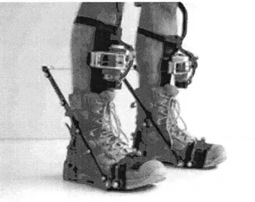
Mooney's exoskeleton was developed within the past few years; the first paper about Mooney's exoskeleton is from May 2014 [10]. Mooney's exoskeleton was the first autonomous exoskeleton proven to decrease the metabolic rate of walking. A picture of this exoskeleton can be seen in Figure 2-1.
Figure 2-1: The Mooney exoskeleton has fiberglass struts on either side of each boot. The motor and winch system straps to the shin. The struts are connected to the motor with a cord, and during the toe-off portion of the gait cycle the motor-activated winch system causes the tops of the struts to move rapidly forward, creating a torque around the ankle. [11]
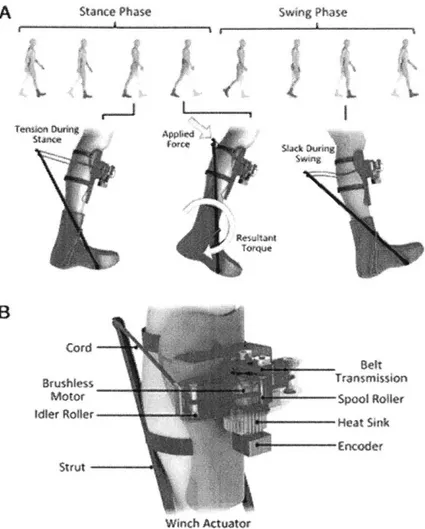
Ankle exoskeletons focus on adding torque to the ankle joint to decrease the metabolic rate of walking. This exoskeleton adds power to the ankle during toe-off in the gait cycle. The Mooney exoskeleton has been found to decrease the metabolic rate by 10+30% by providing net positive mechanical energy to the ankle.
The Mooney exoskeleton has a fiberglass strut on each side of the boot. These struts are attached to the boot near the metatarsal joint with one large bolt that goes through the rubber sole of the boot. The struts are also constrained by a cord that loops through a notch in the struts. This cord runs through the bottom of the boot, in two separate holes. The top of the strut is attached to a separate cord that connects to a winch system. This winch is in turn connected to a motor that is strapped onto the shin. The winch actuator system can be seen in Figure 2-2.
A
B
toni,
Figure 2-:(A) The movement of the exoskeleton at various points in the gait cycle. Power is applied to the body at toe-off by the activation of the winch system applying a force at the tip of the struts', thereby creating a torque around the ankle. (B) The winch actuator uses rollers in combination with the motor to draw in the cord, causingy the tips of the struts to be pulled
forward. [10]
The conmection between the exoskeleton control and the gait cycle can be seen in
Figure 2-2. During stance phase, the struts are held in tension as the exoskeleton prepares to
apply force. Toe-off occurs as stanhe av morphs t inc sing phase. At toe-off, the winch system is activated, causing the tops of the struts to move towards the winch actuator. This motion causes a torque around the ankle, which assists in pushing the ankle forward and into
swing phase. While the foot is in swing phase, the winch unwinds, allowing the cord to become slack. This helps ensure that the foot is relatively unconstrained during swing phase, allowing the foot to have a near-normal gait. At heel-down, the transition from swing phase to stance phase,
the winch system begins to activate, causing the struts to be held in tension. This version of the Mooney exoskeleton was used until the summer of 2015.
2.3 Mooney Exoskeleton-Beta Prototype
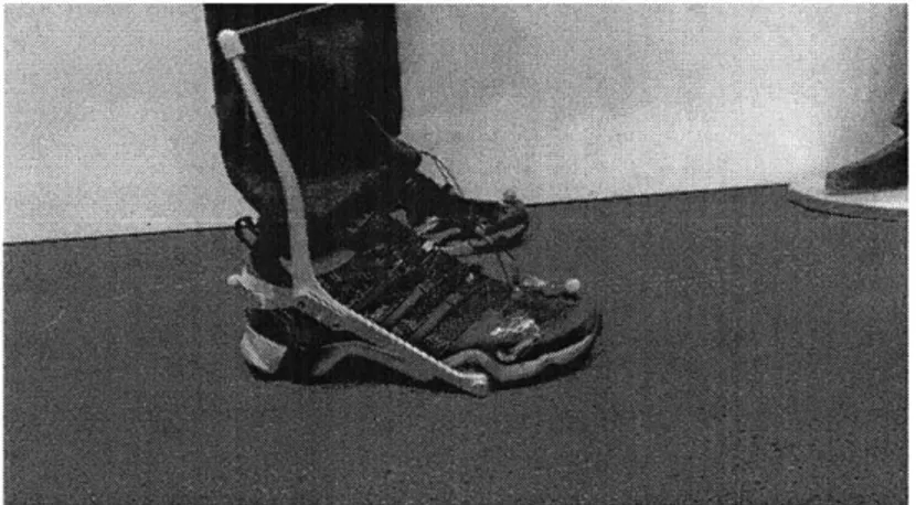
The beta prototype of Mooney's exoskeleton was developed during the sumrnmer of 2015. The beta prototype of the exoskeleton uses angled 7075-T6 aluminum struts instead of the original fiberglass struts. The bottom of the strut is bolted to the shoe as in the alpha prototype, while the middle of the strut is constrained with nylon webbing which is bolted to the underside of the shoe using a singular screw. These struts and the way the struts are attached to the shoes allow the struts to remain closer to the ground and more easily aligned (neither bowed inwards towards the calf nor bowed outwards away from the calf). Finally, the struts were attached to sneakers instead of boots. A picture of the beta prototype can be seen in Figure 2-3.
Figure 2-3: The beta prototype of the exoskeleton uses angled 7075-T6 aluminum struts. The bottom of the strut is bolted to the shoe as in the alpha prototype, while the middle of the strut is constrained with nylon webbing which is bolted to the underside of the shoe with a singular screw. Instead of thick boots, the struts are attached to sneakers.
2.4 Exoskeleton Comparisons
A decreased metabolic rate is the accepted method for determining the efficacy of
assistive exoskeletons for users Without a gait pathology. The Mooney exoskeleton was the first exoskeleton to have a proven metabolic benefit while walking. The author hypothesized that metabolic rate is affected by the mass of the exoskeleton along with the mechanical power
provided by the device. Numerous other exoskeletons add power to the body while walking, but they are generally so heavy that the weight cancels out the power added, causing a detrimental effect on the metabolic rate. The Mooney exoskeleton is designed to be simple and exceptionally lightweight, while adding biological levels of power. The author developed the Augmentation Factor (AF), a model designed to calculate the expected metabolic benefit or detriment of a worn exoskeleton, based on applied power by the exoskeleton, power dissipated, and mass of
exoskeleton on various limbs of the body [10]. A metabolically beneficial exoskeleton would have a positive AF, while a metabolically detrimental exoskeleton would have a negative AF. The Mooney exoskeleton was designed to have a positive AF, accounting for power applied, power dissipated, and mass. The entirety of the Mooney exoskeleton, which included batteries, motors, and controllers, only added 4 kg to a subject; 2.3 kg on the legs and 1.7 kg on the waist (controllers, batteries, and waist pack) [10]. This is much lighter than the 11.7 kg of the quasi-passive exoskeleton described above. This minimalistic exoskeleton was also able to add 23 2 W of mean positive mechanical power during toe-off [10], which is a significant amount of power. In contrast, a passive exoskeleton is unable to add any mean positive mechanical power. The Mooney exoskeleton was the first autonomous exoskeleton to effectively balance the power-weight ratio, and as of the writing of this thesis is still the most effective exoskeleton at balancing this ratio, with the largest decrease in metabolic rate.
2.5
Limitations of Mooney Exoskeleton
While the Mooney exoskeleton has the largest decrease in metabolic rate, it also has certain limitations. The struts extend outwards from the shoes, so users who walk with their feet close together may cause the inner struts knock against each other, causing imbalance to the user. For the same reason the exoskeleton is also less effective with other mild gait abnormalities, such as users with out-toed gaits.
In addition, the exoskeleton struts are unable to be easily removed from the shoe, as they are bolted directly to the shoe. Different shoe-and-strut combinations must be created for each shoe size used in data collection. To test a control shoe, the user must remove the
must also be fitted to the user. This also detrimentally impacts the commercial viability of the exoskeleton, as the exoskeleton should be easy to use with a variety of shoes.
This thesis aimed to create a flexible exoskeleton-to-shoe interface that is lightweight, size-variable, easy to fit onto various shoes, and has similar stiffness levels to a bolted exoskeleton. This would address several limitations of a bolted exoskeleton, improving data collection and the commercial viability of the exoskeleton.
Chapter 3
Exoskeleton-to-Shoe Interface Design
The exoskeleton-to-shoe interface, or attachment system, went through many iterations. This section will describe the design iterations, from initial brainstorming to the final prototype.
3.1 Inspiration and Brainstorming
The goal of this research was to make an exoskeleton-to-shoe interface such that the exoskeleton could be attached to shoes without modifying the shoes themselves. This interface should have low don and doff times (time required to place the interface onto the shoe and remove the interface from the shoe), be generalizable to different shoe sizes and types, and be lightweight and sturdy.
Initial inspiration stemmed from similar types of shoe attachments. One such shoe attachment system is crampons (seen in Figure 3-1), used for ice climbing. Crampons are lightweight, sturdy, fit different shoe sizes and somewhat different shoe types, and have relatively short don and doff times. Crampons often use a combination of rigid and flexible materials, such as semi-rigid plastic, small pieces of metal, and nylon webbing. However, crampons are able to use the entire underside of the shoe to act as a backbone for the design, adding a large amount of stability to the crampon. In contrast, the exoskeleton interface harness must leave the bottom of the shoe relatively untouched. The exoskeleton relies on the grip of the shoes themselves to ensure safety and ease of walking. Therefore, while crampons were a definite inspiration, it was not possible to simply mimic the design.
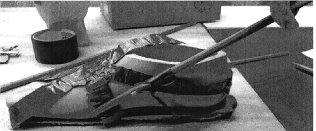
Initial brainstorming was conducted with cardboard, duct tape, and wooden sticks around a rubber foot, and can be seen in Figure 3-2. This was an attempt to gain intuition into how the exoskeleton interface would sturdily hug a shoe. This brainstorming showed that different loops of material would likely be required to contain the shoe at various points. For
example, one loop would constrain the ankle, while another loop would constrain the front of the shoe.
V.
Figure 3-1: The Petzl LynXTM Crampon and other crampons were an inspiration for the interface harness due to the lightweight and sturdy design of the crampons, as well as the ability to use crampons with a variety of shoes.
Figure 3-2: Initial brainstorming was conducted with cardboard, duct tape, wooden sticks, and a rubber foot to attempt to gain intuition into the design of an exoskeleton-to-shoe interface.
I
3.2 Exoskeleton-to-Shoe Interface VI
Initial prototypes focused on using a variety of primarily flexible materials. These materials were chosen to keep the weight low and fit to a variety of shoes. The struts that were used in the prototype were the same struts used in the Mooney exoskeleton. A diagram
illustrating the forces on a strut can be seen in Figure 3-3.
q
The prototypes primarily used nylon webbing, because it is both strong and flexible. Velcro was used to assist in constraining the struts, to ensure the struts would not bow outwards unnecessarily. Velcro was also used in other areas to help fit the prototype to different shoe sizes. The distal ends of the struts were placed in hand-sewn nylon webbing pockets. The distal ends of these struts were circular, and the pockets were designed to hold the struts such that the struts could be placed into and removed from the pockets by hand by applying force in the proper orientation, but would not fall out during regular use of the exoskeleton. Initial prototypes can be seen in Figure 3-3 and Figure 3-4.
PA,
f
Figure 3-3: A diagram illustrating the forces on a strut shows that the strut should balance three separate forces: the ground reaction forces on the distal end of the strut, the force from the string and winch system at the proximal end of the strut, and a tension force from the heel cord
constraining the rotation of the strut in the sagittal plane.
These prototypes were effective on the thick, sturdy boots. The struts remained parallel to the shoes, and did not bow inwards or outwards. The desired and undesired directions of movement can be seen in Figure 3-5. The prototypes were also lightweight and were sturdy when used with the boots. However, when these prototypes were transferred to other shoes (more delicate boots and sneakers) they were found to be ineffective. The thick rubber sole of the boots and the general thickness of the boots were needed to constrain the struts to remain parallel to the shoes. When the support of the shoes were removed, the prototype did not create enough support
for the struts, causing the struts to bow inwards and outwards when force is applied. The exoskeleton depends on consistent motion of the struts with the struts remaining parallel to the shoe, as the struts are used to transfer power from the motor to the ankle. If the exoskeleton interface harness were to be commercialized, it would need to work with a variety of shoes, rather than a specific style of boots. Therefore, these early prototypes were not an acceptable long-term solution.
Figure 3-4: Initial prototypes were primarily made of nylon webbing, but other materials such as Velcro and rope cord were used as well. Many elements of the prototype were hand-sewn. The bottoms of the struts are encapsulated in hand-sewn nylon webbing pockets, and can be placed and removed with force applied in the correct orientation, meant to eliminate accidental
Figure 3-5: (A) shows the desired parallel motion of the struts. (B) shows the undesired direction
of bowing inwards (towards the shoe) and outwards (away from the shoe).
3.3 Exoskeleton-to-Shoe Interface V2
Since the usage of only flexible and serni-flexible materials in the initial prototypes was problematic, the following prototypes experimented with adding a rigid component. An aluminum component was created to interface with the bottoms of the struts. The first version of this was created by manually cutting and bending aluminum, and can be seen in Figure 3-6. The
addition of a rigid component seemed to be effective and prototyping then continued with a rigid component. In addition, the rest of the interface harness was simplified significantly. Instead of nylon webbing, Velcro, and a variety of other flexible or semi-flexible materials, nylon webbing, plastic buckles, and thread were used. Cord was also used underneath the aluminum, to constrain the aluminum section to fit closely to the shoe. In comparison to Figures 3-3 and 3-4, the design
Figure 3-6: Aluminum was cut and bent manually, and nylon webbing pockets were attached to the aluminum. The nylon webbing harness section was significantly simplified, and only used an ankle strap, a below-heel strap, and a connection to the aluminum. Cord was used underneath the aluminum to constrain the aluminum to the shoe.
The next version of the prototype focused on adding size-variability to the
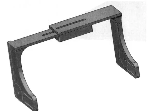
aluminum section. Different shoe types and shoe sizes are not simply different lengthwise; shoes vary significantly in width. Therefore, the next aluminum prototype was made with two distinct pieces of aluminum, and can be seen in Figure 3-7. The right and left pieces connect with the use of small bolts in the slide. In addition, the nylon component of the harness also interfaces with the bolts in the slide. In this prototype, bolts were used to attach the struts to the aluminum component. Strings were used on the underside of the aluminum to secure the aluminum to the shoe.
This prototype was found to be both minimalistic and relatively secure. However, the adjustment of the slide bolts significantly lengthened the time required to fit the prototype to the shoe. In addition, the strings on the underside of the aluminum were too bulky and could cause a person to trip or slip. Therefore, a computer-aided design (CAD) model of a new design was developed and can be seen in Figure 3-8.
Figure 3-7: The aluminum portion was created using a waterjet and then bent into shape. It is made of two separate components with a slide to vary width that is secured with bolts. Bolts were also introduced in this prototype to attach the aluminum to the struts, in a manner much more secure than the nylon pockets.
This CAD model used a slide system that was based on the aluminum prototype. Having two separate, parallel slides was found to be unnecessary if the slide was otherwise appropriately constrained, so only one slide was designed and the slide was constrained from the outsides of the design. The outer slide portion was created so that the nuts sit on the bottom inside of the slide while the slide is being adjusted. This allows for easier loosening and tightening of the slide bolts, as the nuts would not need to be removed and would not be in danger of falling off the slide. In addition, slits were created at the sides of the model to hold nylon webbing. This webbing would be used instead of strings to wrap around the underside of the shoe. Nylon webbing is much flatter and therefore less likely to lead to tripping or slipping. The model was intended to attach to the nylon webbing harness seen in the earlier aluminum prototype. The model would be 3D printed using PLA (Polylactic Acid) to quickly test the form and function, with the ultimate goal of machining the final prototype out of a more durable
However, before the CAD model was turned into a physical prototype the Mooney exoskeleton switched to the beta prototype (see Figure 2-3) for reasons described in Chapter 2. Since the struts were designed completely differently, and sneakers, rather than boots, became the primary shoe associated with the exoskeleton, more brainstorming and designing was required.
Figure 3-8: The CAD model of the new version used a slide system based on the aluminum prototype. Only one slide section was used, as having two slides was found to be unnecessary. Instead of strings wrapping around the underside of the shoe, slits were created in the model to allow nylon webbing to hold the model to the underside of the shoe.
3.4 Exoskeleton-to-Shoe Interface V3
While the switch to the beta version of the Mooney exoskeleton initially appeared disadvantageous, it actually allowed the design to be simplified. Since the beta version was designed to be more stable, using similarly angled struts as in the beta exoskeleton allowed the next versions of the interface additional stability. This change of strut design allowed for changes in the exoskeleton-to-shoe interface geometry.
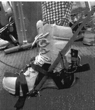
An initial prototype can be seen in Figure 3-9. For the first time, "lock laces" were used. These lock laces are a strong, stretchy, flexible shoelace that are held tightly instead of tied. These lock laces, along with the plastic buckle for the nylon webbing at the bottom of the struts,
assisted the prototype's size variability. The lock laces were also strong enough to hold the prototype tightly to the shoe.
This new design was lightweight and easily size-variable. Since the struts were originally designed for the Mooney exoskeleton, channels for the nylon webbing were created using duct tape. The struts therefore were not properly constrained, and moved up and down when force was applied. This prototype did not truly test the full system, but represented a major improvement. The new strut design allowed the removal of a more rigid and heavier metal or plastic component.
Figure 3-9: This prototype tested the use of lock laces with an interface harness made almost exclusively with nylon webbing. The interface harness has size 'variability due to the buckle at the bottom of the struts. As these struts were originally designed for the Mooney exoskeleton, duct tape was used to create a channel for the nylon webbing at the front of the shoe.
3.5
Final Design of Interface
After a tewv iterations of strut design, the final struts were developed to interface directly with the attachment system, and in doing so the struts becamne a direct component of the
interface harness. These struts were created out of 6061 -T6 aluminum using a waterjet. The struts were angled to be similar to the struts used in the Mooney beta prototype, while interfacing with the nylon webbing components of the interface harness. These were designed with small
aluminum attachments that bolt on to the struts to constrain the nylon webbing, ensuring the struts would not slide. Qualitative testing determined that only the back attachment at the heel was necessary, and the front of the strut remains secure without the extra attachment near the metatarsal joint. The entire exoskeleton-to-shoe interface without the struts weighs 73.9 g. The control bolts and necessary attachments (without the struts or the shoe) weigh 62.4 g, 11.5 g less than the prototype.
The final design was influenced by the prior iterations and can be seen in Figure 3-10. Compared to the initial harness designs, the final prototype was both the most flexible and simple. The rigid frontal component of earlier prototypes became unnecessary due to the redesign of the rigid and now angled struts.
I I$
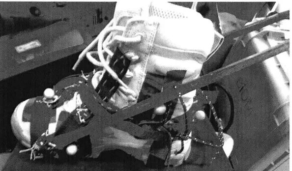
Figure 3 -10: The interface harness can be attached to a variety of different shoe types and sizes. (A) shows a Women's size 8 sneaker. While the front strut-nylon webbing attachment is shown in this picture, it was found to be unnecessary and was not used in testing. (B) shows a wide, thick tennis shoe, Men's size 9.5. (C) shows a flatter Converse sneaker, Men's size 10.
To place the interface harness onto a new set of shoes, only the front and back nylon webbing, plastic buckle, and lock laces must be adjusted. Therefore, the time to place the harness onto a new shoe while wearing the shoe is under 2 minutes for practiced personnel. Also for trained personnel, the time to remove the harness from the shoe (while wearing the shoe) is about
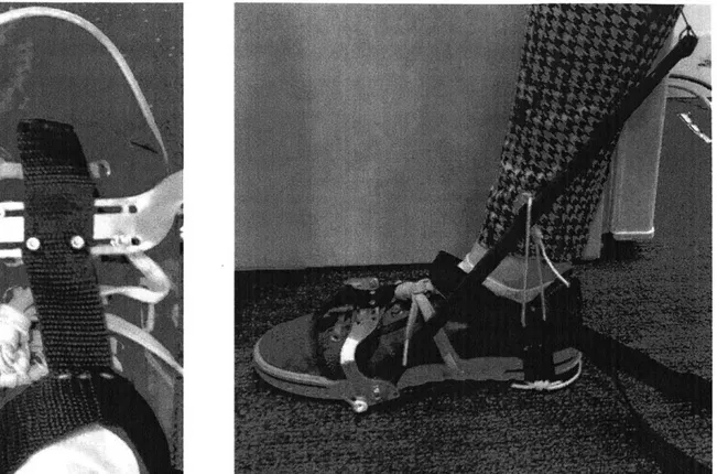
15 seconds, while the time to place the harness onto the same shoe as before (while wearing it) is about 30 seconds. These don and doff times are quite short, showing the ease of use for the final design of the interface. The final interface harness on various sizes and types of sneakers can be seen in Figure 3-10. Figure 3-11 shows a close-up of the strut-to-nylon webbing interface.
This interface harness was qualitatively tested and found to be very sturdy on a variety of shoes. Since the interface harness was lightweight and easy to apply and remove, this qualitative test determined that the final prototype was ready for quantitative testing.
Figure 3-1 1: The nylon webbing loops into the strut through two slots in the strut. These slots constrain the strut-to-nylon webbing attachment well enough that the aluminum attachment piece was found to be unnecessary.
Chapter 4
Testing of Attachment Stiffness
Testing was conducted to compare the stiffness of the exoskeleton-to-shoe interface harness to the stiffness of an exoskeleton that is bolted to a shoe. The motor and controls components of the exoskeleton exerted force on the struts, and the time-varying strut deflection was measured using motion capture. The stiffness of the exoskeletal attachment was calculated from the force and the angles created by strut deflection, and was compared between the two cases.
4.1 Experimental Design
Testing was conducted with the torque applied at a maximum magnitude of
approximately 15 Nm. The torque was applied as a triangle wave and tested at frequencies of 0.5 Hz, 1 Hz, and 2 Hz. To conduct this test, the interface harness was compared to a bolted
exoskeleton whose struts had the same profile as the interface struts. This bolted exoskeleton can be seen in Figure 4-1.
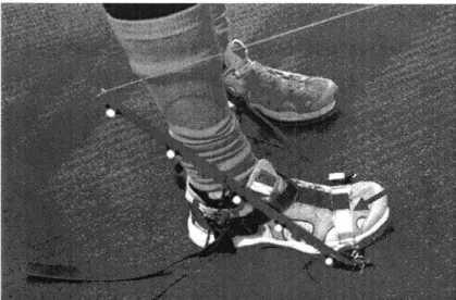
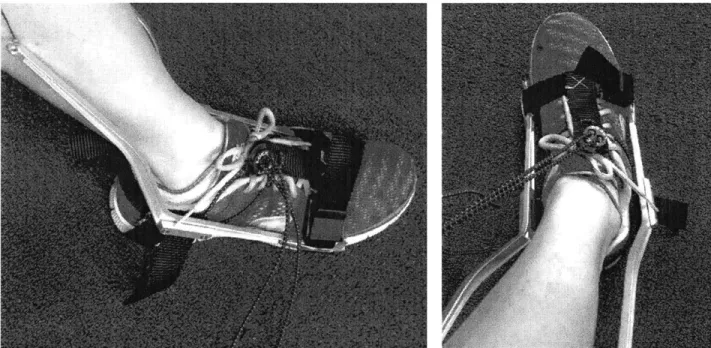
The time-varying angle of the attachment, the other parameter required to calculate stiffness, was found using motion capture (camera model: T40s, Vicon Motion Systems Ltd, Oxford, UK). Nine motion capture markers were placed on the subject and exoskeleton: toe, heel, shank, and the top, middle, and bottom of both struts. Figure 4-2 shows the experimental
setup. The goal of testing was to compare the stiffness of attachment between the bolted exoskeleton and the interface prototype.
Figure 4-1: The struts for the bolted exoskeleton have the same proftile as the interface harness struts, to optimally compare between the two sets of data. These struts were also made out of 6061 -T6 aluminum using the waterJet.
Figure 4-2: Motion capture markers were placed at the toe, heel, and shank, as well as the top, niddle, and bottom of each strut. The motor and controls system of the Mooney exoskeleton were used to apply force to the tops of the struts.
4.2 Measurements and Discussion
Strut deflection can be measured using the motion capture markers. When synchronized with the force applied on the strut, the stiffness of the interface harness can be found by taking the slope of a T-O graph, where u is the torque on the struts and 0 is the angle between the line formed by the toe and heel markers and the line formed by the averages of the bottom and middle strut markers.
The embedded electronics of the exoskeleton collected the measurements of force applied to the struts, and from this data collection T, the filtered torque as a function of time, was interpolated.
The stiffness of attachment calculation required finding a specific angle in the system. This angle was determined by placing all the markers onto a reference plane, with the normal vector for the reference plane defined by
= '(dH - T) X (3~ -T),(
where dH is the 3-dimensional, time varying, position vector of the heel marker, d7 is the position vector of the toe marker, and a3 is the average position vector of the medial and lateral markers at the proximal ends of the two struts. Initially the plane was planned to consist of the toe marker, heel marker, and shank marker, but the shank marker was not fully captured by the motion capture system. The average of the proximal strut markers was an acceptable substitute. The markers were projected onto the place using
dx,p = dx ((dxdT)- )*ii, (2)
where dx is the original marker (i.e. dH, T, d1, d2, or a3 ) and dx,p is the projected marker. After all markers were projected onto the reference plane, two lines were defined and can be seen in the schematic shown in Figure 4-3. To calculate the angle required to find the attachment stiffness, the changing angle between these lines is found as a function of time with
-1(dH.p-T,p)(d2,p-d1,p)
0 = Cos- (3)
1dH,p -aT,pJ|a2,p -a1,p|
where d2,p is the projected marker at the middle of the strut and d1,, is the projected marker at
the distal end of the strut. This angle was then filtered using a third order, zero-lag butterworth filter with a 10 Hz cutoff frequency.
At this point, the data consisted ofT as a function of time and 0 as a function of time. However, as the data was collected from two separate sources (the controls component of the exoskeleton and the Vicon motion capture system), the data uses two offset timescales. Therefore, the timescales of the two sets of data were visually aligned by comparing the first peaks. In addition, the torque from the exoskeleton had a slightly irregular timescale, so linear interpolation was required to fully align T and 0. A comparison between z and 0 before and after
time-shifting can be seen in Figure 4-4.
The stiffness of attachment was then calculated. Once the data were aligned, stiffness was calculated by plotting T on the y-axis and 0 on the x-axis and fitting a linear
function. The attachment stiffness is estimated as the slope of the linear fit. The final outputs are shown from Figure 4-5 to Figure 4-10. This method was used for all three frequencies, and the stiffness data acquired from these graphs is presented in Table 4-1.
a
3a
2,Aal
M aH
Figure 4-3: Schematic of markers and associated lines. ar is the toe marker, a[ is the heel marker, and a,, a2, and a3 are the markers on the distal end, middle, and proximal end of the strut
respectively. ar and a, form the reference line, and a, and a, form the line used to find the stiffness of the attachment. The changing angle over time, when plotted with changing torque over time, can be used to determine the stiffness of the attachment.
Initial Torque and Angle
4
St
4 4
210 12
Timnle (S)
Time-Shifted Torque and Angle
S2 4 (3 e 10 '12 14
Time (s
Figure 4-4: Peaks before and after visual alignment for the prototype at 2 shifled to align the peak torque with peak angle.
l -z. The timescale was
aT
r
16 V-z C 14 -12 6j 4 2 8,082 x -2-94.2 0.5 Hz Prototype 366 36. 8 37 37 2 37 4 7 6 37 8 3M 32 38.4 Angle (Deg)
Figure 4-5: The torque and angle data were plotted continuously for a relevant range of data. The slope of a linear fit line is then the stiffness. For the prototype at 0.5 Hz, the slope and therefore stiffness was found to be 8.082 Nm/.
16 y143x -23. 14 12--z 2r 10 8 tj 38>5
71/,
0,5--->~- ' Hz, 40 Angle (Deg)-I
I
40 5 41 41 5Figure 4-6: The torque and angle data were plotted continuously for a relevant range of data. The slope of a linear fit line is then the stiffness. For the control at 0.5 Hz, the slope and therefore stiffness was found to be 6.143 Nm/.
39 39.5
y =
Q 36.4
14-12F
10F E, 0 y =1029x - 3713 iHz, Prototype 'Ner 36 362 36 4 36. 36 8 37 372 374 37.6 378 Angle (De~g)Figure 4-7: The torque and angle data were plotted continuously for a relevant range of data. The slope of a linear fit line is then the stiffness. For the prototype at 1 Hz, the slope and therefore stiffness was found to be 10.29 Nm/.
I~ ~ ti F-E z a-, 14 12
F
it k-242x - 241.4 I Hz tj t 38, 5 39 39.5 4 0 Angle (Deg )Figure 4-8: The torque and angle data were plotted continuously for a relevant range of data. The slope of a linear fit line is then the stiffness. For the control at 1 Hz, the slope and therefore stiffness was found to be 6.242 Nm/.
36 j 1 .11.111- 1-1. 1 A - ... . 6 4 y = 6. 6 . Conrrd NVr 41 41 5
20 ~14 6 4 36.2 1694'x 6132 .H Prototype3 36,6 37 37.2 Angle (Deg)
Figure 4-9: The torque and angle data were plotted continuously for a relevant range of data. The slope of a linear fit line is then the stiffness. For the prototype at 2 Hz, the slope and therefore stiffness was found to be 16.94 Nm/.
01
Y 6.9574x -271A4 12L
10 z 20 2 --- - z _O m; t 41 40 4C Arigle (Deg) 415Figure 4-10: The torque and angle data were plotted continuously for a relevant range of data. The slope of a linear fit line is then the stiffness. For the control at 2 Hz, the slope and therefore
stiffness was found to be 6.957 Nm/.
'E
12-z
-io-L
Table 4-1: The prototype had greater stiffness than the control at all frequencies. The control stiffness varied less than 1 Nm/, while the prototype stiffness varied about 9 Nm/0.
approximately doubling from 0.5 Hz to 2 Iz.
0.5 Prototxpe 8'082 Control 6.143 I Prototype 10.29 Control 6.24 2 Protvpe 16.4 Control 6.95 7
The control stiffness remained relatively consistent over the various frequencies, with an increase of less than I Nm/ from 0.5 Hz to 2 Hz. However, the attachment stiffness of the prototype was found to be greater at higher frequencies, leading to the stiffness at 2 Hz being double the stiffness at 0.5 Hz. Further research would be required to explain why the results varied by frequency. One possible explanation is due to the foam sole of the sneakers used in testing. The control shoe used a heel strap bolted to the shoe. To bolt this strap, a section of the
foam sole was removed from the shoe. In contrast, the shoe used to test the prototype retained the full foam sole. The viscoelasticity of the foam caused a decrease in stiffness at lower
frequencies, while having a much lesser impact at higher frequencies. While this change in stiffness was large for the prototype shoe, the change in stiffness was lessened in the control shoe, as viscoelasticity is impacted by the thickness of the foam heel and therefore the small layer of foam in the control shoe lessened the effects of viscoelasticity.
In all scenarios the prototype compares favorably to the human ankle. The human ankle stiffness during level ground walking is approximately 8 Nm/, and the stiffness of attachment in all cases was equivalent to or greater than the human ankle stiffness. In contrast, the control was found to be less stiff than the human ankle, representing an advantage of the prototype as
compared to the control. Assuming that the exoskeleton controller should allow stiffness levels comparable to the human ankle, the motor would need to compensate to create higher stiffness levels if the attachment stiffness was lower than the human ankle. Since the stiffness of attachment is greater than the human ankle stiffness, the actuator does not need to compensate for the interface harness.
Chapter
5
Conclusion
This thesis consisted of the design, creation, and testing of an exoskeleton-to-shoe interface. After many iterations of prototypes, the final design of the interface was found to be qualitatively secure, lightweight, and easy to use with short don and doff times. Quantitative testing was conducted to determine the stiffness of the interface harness as compared to a control bolted exoskeleton. The stiffness of the exoskeleton-to-shoe interface was found to increase
significantly at higher frequencies. In contrast, the stiffness of the control remained relatively constant at all frequencies. Further research is required to determine the reasoning behind the change in stiffness at different frequencies. However, in all cases the stiffness of attachment was equivalent to or greater than the human ankle stiffness, which is a promising result.
This positive result from the stiffness test combined with the benefits of a flexible, lightweight, and size-variable exoskeleton-to-shoe interface shows that this interface has potential to be useful in both future experiments and eventual commercialization of the exoskeletons. This interface should therefore continue to be developed and tested further as a useful alternative to the original exoskeleton design.
Future work would include conducting stiffness testing while a user is walking with the exoskeleton, to test whether the interface harness is negatively affected by the greater
movement involved during walking. This would also test the security of the interface harness with additional variables, such as the potential for human error or control failure while using the interface.
Bibliography
[1] N. Yagn, (1890) "Apparatus for facilitating walking, running, and jumping," US Patents 420,179 and 438,830.
[2] J. A. Blaya and H. Herr, (2004) "Adaptive Control of a Variable-Impedance Ankle-Foot Orthosis to Assist Drop-Foot Gait," IEEE Transactions on Neural Systems and Rehabilitation
Engineering, vol 12, 24-31.
[3] K. Kong and D. Jeon, (2006) "Design and Control of an Exoskeleton for the Elderly and Patients," IEEE/ASAlE Transactions of Mechatronics, vol 11, 428-432.
[4] J. E. Pratt, B. T. Krupp., C. J. Morse, and S. H. Collins, (2004) "The RoboKnee: An
Exoskeleton for Enhancing Strength and Endurance During Walking," Proc. IEEE International
Conference on Robotics andAutomation, New Orleans, LA, USA, 2430-2435.
[5] A. M. Grabowski and H. Herr, (2009) "Leg Exoskeleton Reduces the Metabolic Cost of Human Hopping," Journal ofApplied Physiology, vol 107, 670-678.
[6] J. Dick and E. Edwards, (1991) "Human Bipedal Locomotion Device," US Patent 5,016,869. [7] L. M. Mooney, E. J. Rouse, and H. M. Herr, (2014) "Autonomous exoskeleton reduces metabolic cost of human walking," Journal ofNeuroEngineering and Rehabilitation, vol 11, 151.
[8] S. H. Collins, M. B. Wiggin, and G. S. Sawicki, (2015) "Reducing the energy cost of human walking using an unpowered exoskeleton," Nature, vol 522, 212-215.
[9] C. J. Walsh, K. Endo, and H. Herr, (2007) "A quasi-passive leg exoskeleton for load-carrying
augmentation," International Journal of Humanoid Robotics, vol 4, no 3, 487-506.
[10] L. M. Mooney, E. J. Rouse, and H. M. Herr, (2014) "Autonomous exoskeleton reduces metabolic cost of human walking during load carriage," Journal ofNeuroEngineering and
Rehabilitation, vol 6, 80.
[11] L. M. Mooney and H. M. Herr, (2016) "Biomechanical walking mechanisms underlying the metabolic reduction caused by an autonomous exoskeleton," Journal ofNeuroEngineering and