A Design for a Flexible, Low-Cost Rigging Block for Black-Box Theaters by
Michael J. Shields
Submitted to the Department of Mechanical Engineering in Partial Fulfillment of the Requirements for the Degree of
Bachelor of Science in Engineering as Recommended by the Department of Mechanical Engineering
at the
Massachusetts Institute of Technology June 2010
0 2010 Michael Shields All Rights Reserved
ARChVES
7MASSACHUSES
OF TECHNOLOGYINSJUN 3 0 10
ES
The author hereby grants MIT permission to reproduce and to distribute publicly paper and electronic copies of this thesis document in whole or in part in any medium now
know or hereafter created.
Signature of Author...
Departm(
C ertified by... ...
ent dfMechanical Engineering May 27, 2010
Bar ra Hughey PhD Instructor, Department of Me hnical Engineering / t Thesis Sunervisor C ertified by ... ,...& ... ... K atz Michael Katz _ -- Technien1 Ta- Music and Theater Arts Section Thesis Supervisor
Accepted by...
...
John H. Lienhard V -sor of Mechanical Engineering Chairman, Undergraduate Thesis Committee
A Design for a Flexible, Low-Cost Rigging Block for Black-Box Theaters by
Michael J. Shields
Submitted to the Department of Mechanical Engineering on May 27, 2010 in partial fulfillment of the requirements
for the Degree of Bachelor of Science in Engineering as Recommended by the Department of Mechanical Engineering
ABSTRACT
Theater rigging greatly expands both scenic movement and storage options when putting on a production. Small, black-box theaters are often built without rigging
equipment in them. Temporary rigging equipment can greatly add to the flexibility of these spaces.
A rigging block was designed which can be installed in small theaters by
attaching to the existing lighting structure. The design was developed to solve problems encountered when using currently available temporary rigging solutions. The block was designed to lift a 200 pound scenic load while providing a safety factor of 10:1. A dual-pulley arrangement allows for flexibility in the placement of rigging positions and better utilization of the available space. Top and bottom pulleys allow for lines to be routed above the level of the lighting grid. The independent swiveling of the pulleys allows lines to enter and exit the block at different angles, adding significant freedom to the rigging system.
Calculations were done to assess the forces and torques to which the block might be subjected. Potential materials were evaluated based on their ability to withstand these forces. An eye was kept toward using available off-the-shelf parts where possible in order to reduce costs and to allow for the system to be used by small theaters working with limited budgets.
Thesis Supervisor: Barbara Hughey
Title: Instructor, Department of Mechanical Engineering Thesis Supervisor: Michael Katz
Acknowledgements Mike Katz Barbara Hughey Lori Hyke Gayle Merling James Shields Elizabeth Shields Maura Cordial Franz Hover
Table of Contents
Introduction 5
The Design Problem ... 7
Loft Blocks 7 Head Blocks .. 88... Safety8... Existing Solutions...9
The Design11... 11
Structural Analysis.2...12ForDesiq...13..I Torce 14 Torque ... 1.4 Bending ... 15 Materials Selection 15 Clamp ... 16 Hub Tubing ... 17 Bearings ... 17 Summary ... 18 Future Work References ... 19 List of Figures: Figure 1 - Standard Proscenium Theater ... 5
Figure 2 - Standard Ri in Setup ... 6
Figure 3 - Black-Box Theater ... 66... Figure 4 - Grid of the Loeb Experimental Theater ... 7
Figure 5 - Diagram of Fleet Angle ... 8
Figure 6 - Clancy Temporary Rigging Block ... 9
Figure 7 - Diagram of Running Line with Clancy System ... 10
Figure 8 - CAD Model of Block Assembly ... 1
Figure 9 - Line Arrangements for Max Tension and Compression 13 Figure 10 - Line Arrangement for Max Torque ... 14
Figure 11 - Line Arrangement for Max Bending ... 15
Figure 12 - Doughty Engineering Scaffold Coupler ... 16
List of Table: Table 1 - Comparison of Design Requirements and Material Properties ... 18
Introduction
Scenery is an essential part of any theater production: it provides information to the audience about where a scene is occurring and is used to support the themes of a play. One great challenge for the crew of a show is finding a place to store scenery when it is not being used onstage. Backstage space is always at a premium in a theater. Scenery and props must be stored in limited offstage space when not in use, but must not impede the movement of the cast and crew. Being able to fly scenery out of sight over the stage frees up valuable space in the offstage wings. In addition to conserving space, the way in which scenery moves also affects the tone of the show. As much as well planned
transitions can add to a performance, poorly executed ones can serve to ruin an otherwise fantastic show. Proper rigging can allow for scenery to not only be hidden offstage, but
also to be moved around onstage in the way called for by the designer.
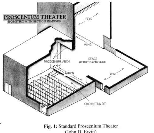
Fig. 1: Standard Proscenium Theater (John D. Ervin)
Traditional theater architecture (see Figure 1) includes a fly loft over the stage where flying scenery can be raised and stored overhead, rather than occupying offstage space in the wings. Fly lofts are typically rigged with numerous battens (hanging pipes) supported by rigging lines of either rope or cable, as shown in Figure 2. These ropes run up to an overhead truss structure (referred to as the "grid"), where they run through loft blocks to head blocks and then to the pin rail, from which they are adjusted by a crew member to raise or lower the scenery. In this traditional system, the battens run in straight lines, parallel to the front of the stage. The loft and head blocks are permanently attached to the grid above the stage, limiting the placement of flying scenery.
Fig. 2: Standard Rigging Setup (Jay 0. Glerum)
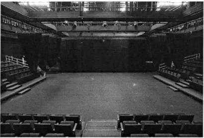
Many small theaters do not have the ability to use flying scenery due to their architecture. Black-box theaters (see Figure 3) are essentially empty rooms that have been adapted for theatrical use. One of the few features distinguishing these rooms as theaters is the installation of a lighting grid, a series of overhead pipes from which lighting equipment is hung. The advantage of black-box theaters is the freedom that they afford designers to use the space as they wish. However, these theaters require more work on the part of the crew as even the most basic elements such as the stage and
audience seating must be built from scratch. Black-box theaters, being featureless rooms, have no wing space (unless it is artificially created using curtains). This lack of offstage floor space means that being able to fly scenery out of the way is even more important. A rigging system that can be attached to the lighting grid will allow for basic flying scenery to be used in theaters that do not have fully equipped fly lofts, or have no fly space whatsoever.
Fig. 3: Black-Box Theater (Central Washington University)
The Design Problem
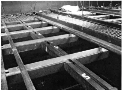
The goal of this thesis project is to design a loft block that will allow a basic rigging capability to be added to theaters that do not have such equipment built into them. This block will be able to be attached to a standard lighting grid, made of 1.5" steel pipe (see Figure 4).
Fig. 4: The grid, including lighting pipes, of the Loeb Experimental Theater
The attachment of the rigging equipment to the grid is one of the most important aspects of the design. The components must be solidly attached to the grid structure so that they do not come loose and rotate around the pipe, changing the angle of the running lines, or, in a worst-case scenario, detach from the grid completely. The attachment process cannot be complicated, as the crew member working on the rigging is likely to be working one-handed while balancing atop a ladder.
Loft Blocks
Non-swiveling, fixed loft blocks limit the routes available for running lines to matching the structure of the lighting grid. A design for a loft block assembly that includes the ability to swivel would allow for significantly improved flexibility in the placement of running lines and other rigging equipment both over the stage and backstage. Loft blocks with the ability to rotate would free flying scenery from the restrictive placement dictated by linear battens. In addition to onstage placement concerns, the scarcity of backstage space requires that offstage scenery, machinery, and people must be placed wherever room can be found. Also, rigging lines must often be run around a theater's architectural features or to difficult locations where the operator can be hidden from the audience. Swiveling loft blocks would make it easier to run these lines where they need to go.
Swiveling loft blocks would also improve the durability of the rigging system, by allowing the pulleys to better match the alignment of the running lines, minimizing
rubbing of the lines against the pulley housings and the associated wear on the lines caused by sharp fleet angles. The fleet angle is the angle made by a line running between two blocks which are horizontally offset as shown in Figure 5. The offset between the centerlines of the two blocks cannot be too great lest the lines start chafing against the blocks.
distance a fleet angle
3.42 Fleet angle
of line between distance b
offset blocks
Fig. 5: Diagram of Fleet Angle (Jay 0. Glerum) Head Blocks
Head blocks are designed to collect the multiple lines connected to a batten and to bring them together so that they can be operated as a group. Traditional head blocks are
designed to accept running lines that enter the block straight-on. Because the loft blocks from which the lines run are permanently fixed to the grid in straight lines, the head blocks do not need to be able to handle lines that approach from different angles.
Dual-swivel loft blocks, by allowing the angle of a line to be changed mid-run, will allow for freer placement of hanging positions while still keeping the lines in the correct
orientation to enter the head block properly. Safety
The nature of flying scenery, involving large set pieces suspended over the heads of the cast and crew, makes knowing the safe working loads of rigging hardware of critical importance. Theater technicians commonly refer to a "safety factor" when designing rigging systems, defined in Eq. (1):
Safety Factor = Ultimate Strength
Working Load
The safety factor is the ratio between the ultimate strength of the rigging hardware and the working load of the associated scenery. The safety factor helps guard against the unknowns that arise when designing rigging and scenery. These unknowns can include such things as variations in the weight of scenic loads or in the forces which come into play in a dynamic system, such as frictional forces in the rigging system or changes in the length of rope needing to be supported as the scenic element moves. Safety factors can vary depending on the situation. Hanging a lightweight gauze curtain that does not move is much less dangerous than rigging a full-height solid wall that needs to fly on- and off-stage. Theatrical safety factors usually fall between 5:1 and 10:1. This project will use a conservative safety factor of 10:1.
Many of the theater companies that perform in black-box theaters are educational or non-profit groups and therefore work with limited funding. As such, one of the goals of this project is to keep the cost of the system to a minimum. Additionally, the goal of any theater crew is to make the mechanics behind a show as invisible as possible. A secondary goal to system strength and cost will be to keep the components as small as possible so that they can be better hidden from the view of an audience.
Existing Solutions
The MIT Theater Arts Department currently has a system designed for use in Kresge Little Theater by JR Clancy, one of the leading theater rigging manufacturers in the US. The existing system fulfills some of the design goals of the present work, such as the ability to introduce minimal rigging functionality into a theater by attaching to the existing lighting grid. While this system is better than nothing, there are several
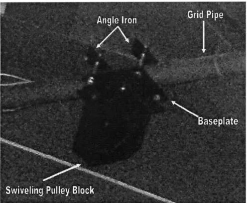
downsides. The current system is bulky and very difficult to install. The pulley block is attached to the lighting pipe by bolting it to two pieces of angle iron which then clamp down on the pipe as the bolts are tightened. The problem with this system is that it consists of many different loose pieces, which are at best annoying for the stagehand to assemble while standing atop a ladder or scaffolding and at worst a hazard as they may be dropped on cast or crew members below.
Fig. 6: A Clancy pulley block hanging from the grid of MIT's Kresge Little Theater The Clancy system consists of one swiveling pulley block attached to a baseplate. This system is designed to be underhung from the grid. With such a system, the direction of the line running through the block can only be changed within the plane of the pulley.
This limitation is not a problem when directing a line from immediately above a hanging point to an operator across an open span of stage but with more complicated rigging paths difficulties begin to arise. Any line redirection using a Clancy block cannot include a horizontal component without installing the pulley block at an angle offset from vertical. For example, in order to use the Clancy system to direct a line between two pulleys that are at the same height but at right angles to one another, a third, middle pulley must be mounted completely sideways as seen in Figure 7. Properly matching the needed angle while installing the block overhead is very difficult to accomplish. Even after the block is installed, the weight of the block will try to pull it out of alignment.
Fig. 7: Redirecting a running line using the current Clancy system
The underhung nature of the Clancy system also does not allow the lines to be routed above the rigging system, a serious deficiency for a system designed to hang below the lighting grid. Immediately below the lighting grid is one of the most crowded spaces in a theater, with lighting designers often not finding enough space to fit all of their own desired instruments, let alone the set crew's hardware.
An alternative system that is used for temporary rigging is rock climbing
equipment. This equipment has the advantage of being small and easily installed, as one would hope for something intended to be used by someone who is using one hand to hold onto a cliff-face. While an inventive solution, climbing gear is not ideal. Climbing gear is rated for use supporting loads; however, this rating is usually aimed at loads not much more than that of the human body - not a very significant amount in comparison to some pieces of scenery. Climbing gear is designed only to work with climbing ropes and does not allow the freedom to use larger diameter hemp lines or smaller wire rope. Climbing webbings looped around to attach pulleys to the grid work only in tension and provide no rigidity to the rigging system. It is impossible to position the pulley anywhere but where
the tension of the rope is going to pull it, making it difficult to reroute the line around lighting equipment or any other obstacle.
The Design
The goal of this project was to design a simple, flexible rigging block for use in black-box theaters which would address the problems encountered when using currently available equipment. The block is designed to serve as a temporary rigging solution for smaller theaters. As such, it must be able to support a reasonable scenic load but not one that would compromise the structural integrity of the lighting grid or the building itself. The block is designed to attach to a standard lighting grid made of 1.5" steel pipe, as this grid is often the only overhead feature in small theaters. The block must be able to be installed easily, as installation will often need to be done by a technician in a difficult to reach location. The system is to be able to allow a running line to enter and exit the block at different angles. The block must also be able to direct lines above the grid, out of the way of lighting equipment.
The loft block designed in this project consists of two pulleys, mounted one above the other, tangential to the same vertical axis. The two pulley brackets are connected by a central hub assembly, which can be attached to the lighting grid. The pulleys are able to independently rotate around this central vertical axis in such a way that a rope passing over one pulley will be routed through the central hub of the assembly to the other pulley wheel. The plates holding each pulley are connected by pins, which are spaced close enough together to prevent the pulley wheel from falling out of the block. This provides a safety backup should the pulley bearing fail. The hub is connected to a scaffold coupler, which is able to be clamped to the lighting grid.
The rigging system presented in this paper has been designed to fix problems found when using current systems. The dual-swivel design allows for flexibility in the placement of rigging lines. The top and bottom pulley design allows running lines to be routed into the more open space above the grid. Additionally, the ability of the two pulleys to swivel independently of one another allows for the line to come into the block
from one angle and to leave at another without having to alter the placement of the block relative to the grid. The system has been designed specifically with theatrical loads in mind, rather than having been appropriated from some other purpose. Being designed for
overhead installation, the block must have as few loose parts as possible, in order to minimize the danger of falling objects.
The goal of this project was to design a block that is capable of lifting scenic loads up to 200 lbs. With the safety factor of 10:1 specified earlier in this report, this means that the block must not fail at less than 2,000 lbs. The strength of any rigging
system is subject to the strength of the architecture to which it is attached. The structural strength of a particular theater's architecture will vary on a case-by-case basis. Instead of attempting to determine the failure point of a theater's lighting grid, this thesis will proceed under the assumption that the failure of the rigging equipment will occur before that of the lighting grid itself. The 200 lb limit should assist this goal. The 200 lb working load also means that, possibly with the assistance of a small amount of
counterweighting, one stagehand should be capable of moving the scenery attached to the system, without requiring a winch or any other more extensive equipment.
Structural Analysis
In order to ensure that the parts chosen for the block can survive the forces to which they will be subjected, detailed mathematical analysis is required. There are a huge number of orientations in which the block might be placed depending on the needs of the set or show. The analysis below will assess extreme conditions wherein the
maximum forces to which the block might be subjected will be determined. The goal has been stated that the block be capable of lifting a 200 lb scenic load with a 10:1 safety factor. As a result, these calculations have been conducted using loads of 2000 lbs. These calculations assume massless ropes and ideal pulleys that suffer no friction losses and transmit equal tension in and out.
Force
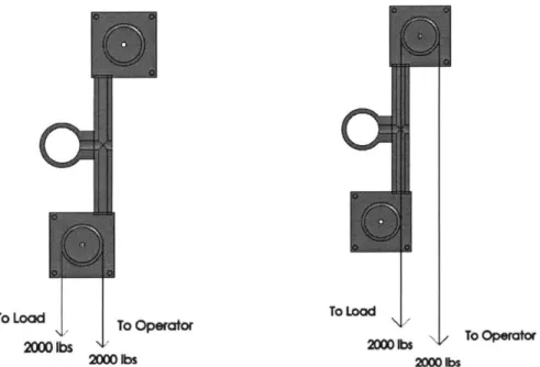
The block must be designed to be strong enough to safely support the scenic loads imposed upon it. If used in such a way that the line enters and exits the block downward, the vertical force acting on the system will be maximized. Such a situation might occur if the block was being used to run a line from an onstage scenic element up and over a wall to an operator hiding out of sight. In static equilibrium, this load will be 4000 lbs.
Dynamic forces are much more difficult to calculate as there are many unknowns, such as the desired speed of movement for the set piece, but these increases are allotted for within the safety factor. The clamp connecting the block to the pipe must be rated to support this load. The vertical forces here also affect the interaction of the swiveling pulley and the fixed central hub. If the top pulley is used, the two elements are in compression. If the bottom pulley is used, the two elements are in tension. The bearing assemblies which
hold the pieces together must be able to withstand these forces.
To Lod To Lo To To LOa
To operor
2000 bs 2000M bs'
200bs 2M an
Fig. 9: The line arrangements which will subject the block to the maximum tension (left) and compression (right)
Torque
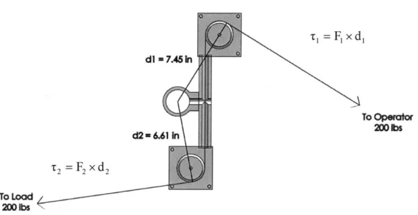
In addition to being able to support the loads placed upon it, the block must be able to resist the torques to which it is subjected. The system will be subjected to the maximum torque about the pipe when the line enters and exits the block in opposite directions, perpendicular to the pipe with the maximum moment arms between the center of the pipe and the force of the line. This arrangement might occur using the block to run a line to an operator while avoiding lighting equipment in the way. The torques
generated by the lines are the product of the distance between the axis of rotation in the pipe and the perpendicular tension force in the lines. The total torque from the two lines must be countered by the force of friction between the clamp and the pipe for the block to remain stable. The safety factor described above is included to account for the possibility of structural failure of a piece of rigging. In the case of line-generated torque, failure to hold means that the block will merely rotate about the pipe, so the safety factor is not required and the torque analysis has been carried out using 200 lb forces. In fact, it would be preferable for the block to fail by spinning well before a structural failure that might result in falling hardware.
d] 7.45 In To Opertor 200 bs d2=6.61 In T2 =F 2 x d 2 To Load 200 bs
Fig. 10: The orientation in which the loft block is subjected to the maximum torque around the grid pipe
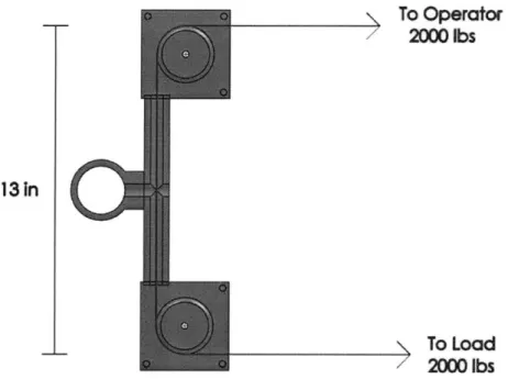
Bending
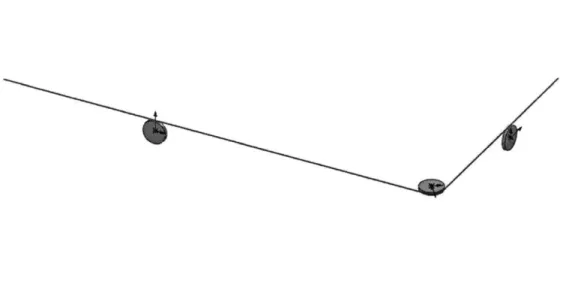
Depending on the orientation of the lines running to and from the block, the hub assembly may be subjected to bending forces. These forces will be at their maximum when the lines enter and exit the block in the same direction, perpendicular to the body of the hub. Such a scenario might occur if the block was used as the turnaround for a line running a curtain or some other piece of scenery set to track across the stage.
Mb = * Length
2 2 (3)
The bending moment exerted on the hub can be found by calculating the moment at one end of the piece relative to the fixed centerpoint, as in Equation 3. The material chosen for the hub must have the size and strength necessary to withstand this force.
13 In
/To Operator
2000 lbs
To Load 2000 lbsFig. 11: The orientation in which the hub assembly is subjected to the maximum bending force/moment
Materials Selection
Having established the forces which the assembly must withstand, candidate materials can be evaluated. The goal of the project is to design a system for use in small theaters, so the focus of part selection was on modestly priced off-the-shelf materials where available.
Clamp
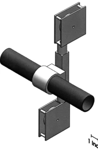
Originally, a standard lighting instrument C-clamp was considered for use in the design. However, it was decided that the single point of force of the bolt in this system was not ideal for countering the potential rotational loads imposed by the rigging. A fully-encircling rated scaffold coupler (Figure 12) was chosen instead, as its greater grip-surface will provide more even distribution of force around the pipe. Additionally, being intended for scaffold use, the coupler is rated for significantly higher loads than a C-clamp intended only to support a single lighting instrument. The coupler chosen, a Doughty Engineering Lightweight Half Coupler, has a weight rating of 1100 lbs, with a
5:1 safety factor, more than adequate for the needs of the design.
Fig. 12: A Doughty Engineering Scaffold Coupler
For the block to remain in proper alignment, it must be able to resist the torque it is subjected to by the rigging. The forces acting on the block could possibly spin it around the pipe to which it is attached. Knowing that for the block to remain stationary it must be in equilibrium, as in Equation 2, the force required of the clamp can be assessed. The force of static friction between the clamp and the pipe must be such that it can resist the torque generated by the lines.
Frictionciamp _ 'Clamp
Great variation exists in the coefficients of static friction between materials due to uncertainty in the nature the two surfaces. It is impossible to know for certain the exact coefficient. Values for metal on metal friction coefficients range from 0.2 - 1.0
depending on the cleanliness of the surface. Using a conservative value of 0.45, the normal force that must be exerted by the clamp to hold the block in place can be calculated.
Friction~ln
Forceciamp i lamp (5)
The clamp must be able to exert at least this much gripping force on the pipe in order to keep the block from rotating under load.
Hub Tubing
As the block may often need to be installed in difficult to reach overhead areas, aluminum would be the preferred material for the central hub in order to reduce the weight of the piece. Calculations were made to see if a square piece of Al 6061-T6 box tubing of an appropriate size would be strong enough to withstand the bending loads to which the hub might be subjected.
Ibeam = (6)
12
ITotal - 'Solid -'Hole (7)
Bending = Mb * Height (8)
Using the ultimate tensile strength of 6061 -T6, 38 ksi1, and potential hub dimensions, the maximum bending moments which the possible hub sizes could withstand were
calculated using Equation 8. The second moments of inertia of the hollow hub tubes were calculated by subtracting the area moment of the hollow section from the area moment of a solid bar with the same external dimensions as the tube using Equations 6 and 7. These strengths of these potential hubs were then compared to the maximum bending moment caused by the action of the lines, calculated above using Equation 3. It was determined that a 2" square Al 6061-T6 box tube with 3/16" thick walls would be more than strong enough to meet the necessary bending strength requirements.
Bearings
Two different possible bearing arrangements have been considered. In one setup, one swivel bearing would be placed at the intersection of the pulley and the hub. This
design is potentially easier to construct, as no parts must be fit inside the hub, but might be less structurally sound. An alternative design is one where the pulley mounting is attached to a hollow shaft which sits within the hollow hub assembly. This shaft would be guided by a pair of bearings mounted inside the hub. This design provides better support to counter forces trying to torque the pulley relative to the hub, but will be more difficult to assemble and maintain with the bearings nested inside the hub. Either design must include bearings which are capable of keeping the pulley connected to the hub when subjected to the axial loads that will be imposed on the system.
Summary
The table below compares the strengths required by the design parameters to the physical properties of potential component materials.
Table 1: Comparison of Design Requirements and Material Properties Design Parameter Value Material Specifications
Tension/Compression 4,000 lbf Clamp rating: 5,500 lbf
Bearing rating for axial load must be able to meet or exceed this load
Torque 230 ft*lbf Clamping Force Required: 6,600 lbf (Equation 2)
Bending Moment 1,100 ft*lbf Al 6061-T6 box tubing: 2"x 2"x 3/16" Wall:
(Equation 3) 1400 ft*lbf
These values represent best-guess calculations in order to obtain an order of magnitude to look for when evaluating potential materials. Once a prototype has been built, extensive testing will be needed to confirm the accuracy of the values for both the design
requirements and the material strengths.
Future Work
At this point, the basic design and materials have been established. Future work on the project will involve prototyping and testing the design. The candidate materials discussed above will be assembled and tested the see if they meet the required standard established earlier. Prototype assemblies will be attached to a section of pipe and subjected to the loading scenarios described above in order to test their ability to withstand the force, torque and bending moments required of the project. Design refinements can then be made based on the information gathered.
References
Ervin, John D. "The John D. Ervin Page of Theatrical Design/Production stuff." (29 Jan. 2008) <www.colby.edu/personal/j/jdervin> (30 Jan. 2008).
Central Washington University -http://www.cwu.edu/~theatre/spaces/spaces.htm Glerum, Jay 0. Stage Rigging Handbook, 2nd Ed. Carbondale, IL: Southern Illinois
University Press, 1997.
Crandall, Stephen H., Dahl, Norman C., and Lardner, Thomas J. An Introduction to the Mechanics of Solids: Second Edition with SI Units. New York, NY: Primis Custom Publishing, The McGraw-Hill Companies, Inc, 1999.