Design and Characterization of Acoustic Pulse Shape
Memory Alloy Actuators
by
Joshua Michael Chambers
Bachelor of Mechanical Engineering (2003)
University of Minnesota
Submitted to the Department of Mechanical Engineering
in partial fulfillment of the requirements for the degree of
Master of Science in Mechanical Engineering
at the
MASSACHUSETTS INSTITUTE OF TECHNOLOGY
June 2005
MASSACHUSETS INSTi E OF TECHNOLOGYJUN 16 2005
L'BARE
LIBRARIES
©
Massachusetts Institute of Technology 2005. All rights reserved.
A u th o r ...
...
Department of Mechanical Engineering
February 28, 2005
C ertified by ...
...
.. .. ...
..
Steven R. Hall
Professor of Aeronautics and Astronautics
Thesis Supervisor
R ead b y ...
. ...
David L. Trumper
P
Accepted by...
Lallit Anand
Chairman, Department Committee on Graduate Students
Design and Characterization of Acoustic Pulse Shape Memory Alloy
Actuators
by
Joshua Michael Chambers
Submitted to the Department of Mechanical Engineering on March 4, 2005, in partial fulfillment of the
requirements for the degree of
Master of Science in Mechanical Engineering
Abstract
Single crystal Ni-Mn-Ga ferromagnetic shape memory alloys (FSMAs) are active materials which produce strain when a magnetic field is applied. The large saturation strain (6%) of Mn-Ga, and material energy density comparable to piezoelectric ceramics make Ni-Mn-Ga an interesting active material. However, their usefulness is limited by the bulky electromagnet required to produce a magnetic field.
In this thesis, a novel actuation method is developed for shape memory alloys in their martensitic phase, whereby asymmetric acoustic pulses are used to drive twin boundary motion. Experimental actuators were developed using a combination of Ni-Mn-Ga FSMA single crystals and a piezoelectric stack actuator. In bi-directional actuation without load, strains of over 3% were achieved using repeated pulses (at 100 Hz) over a 30 s interval, while 1% strain was achieved in under 1 s. The maximum strains achieved are comparable to the strains achieved using bi-directional magnetic actuation, although the time required for actuation is longer. No-load actuation also showed a nearly linear relationship between the magnitude of the asymmetric stress pulse and the strain achieved during actuation, and a positive correlation between pulse repetition rate and output strain rate, up to at least
100 Hz. Acoustic actuation against a spring load showed a maximum output energy density
for the actuator of about 1000 J/m3, with a peak-to-peak stress and strain of 100 kPa and
2%, respectively.
Thesis Supervisor: Steven R. Hall
Acknowledgments
First, I would like to thank my advisor Prof. Steven Hall, who provided the opportunity, motivation, and guidance that made this work possible. His faith in my abilities and eagerness to explore new ideas helped make this project truly unique. Second, I would like to thank Bob O'Handley, who provided lab space and a lab group to work with, as well as providing invaluable assistance throughout the course of this work. Also, a special thanks to Prof. David Trumper for taking time out of his busy schedule to be a reader for this thesis.
I must profess an enormous debt of gratitude to my colleagues in the O'Handley group, for both their friendship and their assistance. Jorge Feuchtwanger and Brad Peterson, who introduced me to the lab, and allowed me to stay, even after my affinity for gravity was demonstrated. David Bono, for his electronics expertise and extraordinary collection of spare parts. Migeul Marioni, Marc Richard, Ratchatee Techapiesancharoenkij, and David Paul, for answering, or at least trying to answer, so many of my impossible questions. Kyungyeol Song, for the chance to see my own research from a different perspective. Jesse Simon, for the opportunity to pass on all that I have learned, and his work gathering and preparing the final sets of data used in this thesis.
Many thanks to the Edgerton Center, and the Edgerton Student Shop, whose machines were instrumental in the creation of many an apparatus. A very special thanks to Fred Cote, whose patience and experience were often the only thing that made my work in the shop productive. Also, thanks to the off-hour shop instructors, David Breslau, John McBean, and Andrew Heafitz.
I would like to thank Prof. Tom Eager for the use of his electronic discharge milling machine (EDM), and Don Galher for allowing the O'Handley group to expedite repairs whenever necessary.
I'm eternally grateful to Leslie Reagan and Joan Kravit, whose extraordinary adminis-trative skills were always able to make mole hills out of mountains.
Of course, to all those I have met at MIT, who made my stay a little less technical and a little more enjoyable, James, Zil, Toby, Sam, Sara, Tai, Jiwoon, everyone from the 2003 MIT-Germany trip and the ME soccer team, and anyone I just had a drink with one night. I thank you for every life lesson, every laugh and every smile.
And, to my family and friends back in Minnesota, I couldn't have done it without you. Finally, I would like to dedicate this work to my grandpa, Hilarius Tauer, who didn't believe in dinosaurs.
This work was sponsored by the Office of Navel Research, grant number ONR-MURI N00014-01-10758, monitored by Dr. Roshdy Barsoum and Dr. Jan Lindberg.
Contents
1 Introduction
1.1 SM A Overview . . . . 1.2 FSMA Overview . . . . 1.2.1 Magnetically Induced FSMA Actuation 1.3 Motivation for This Work . . . .
2 Experimental Apparatus
2.1 Functional Requirements . . . . 2.1.1 Acoustic Pulse Generator . . . . 2.1.2 1-D Finite Element Simulation . . . 2.1.3 Reflector . . . . 2.1.4 Acoustic Horn Dissipator . . . . 2.1.5 Bond Lines . . . . 2.1.6 Drive Circuit Design . . . . 2.2 Single Layer Acoustic Pulse Generator . . . 2.2.1 Impedance Measurements . . . . 2.2.2 Assisted Magnetic Actuation . . . . 2.2.3 Stress Pulse Measurements . . . . . 2.3 Stack Driven Actuator . . . . 2.3.1 Moonie Clamp Design . . . . 2.3.2 Functional Acoustic Pulse Actuators 2.3.3 The Spring Load Testing Apparatus 2.3.4 Piezoelectric Stress Sensors . . . . .
11 11 . . 16 . . 21 . . 26 29 . . . . 29 . . . . 30 . . . . 31 . . . . 33 . . . . 38 . . . . 38 . .. . . . . 41 . .. . . . . 44 . . . . 49 . . . . 51 . . . . 52 . . . . 56 . . . . 56 . . . . 59 . . . . 61 . . . . 66
3 Experimental Results 69
3.1 The First Functional Acoustic Pulse Actuator . . . . 69
3.2 Bidirectional Actuation . . . . 73
3.3 Magneto-Acoustic Actuation . . . . 78
3.4 The Spring Load Testing Apparatus . . . . 79
3.4.1 Steady State Strain Versus Input Pulse Amplitude . . . . 81
3.4.2 Time Dependent Actuation With Various Loads . . . . 85
3.5 Piezoelectric Stress Sensors . . . . 88
4 Data Analysis 93 4.1 Actuation Parameters . . . . 93
4.1.1 Input Voltage, V . . . . .. 93
4.1.2 Gate Voltage, V . . . . 99
4.1.3 Pulse Repetition Rate, fr . . . . 101
4.1.4 Actuator Prestress, c-pre . . . . 101
4.1.5 Load Stiffness, CL . .. . . . . . .. .. . . . .. 103
4.2 Acoustic Pulses and Twin Boundaries . . . . 104
4.2.1 Pulse Shape Observations . . . . 105
4.2.2 Plastic W aves . . . . 108
4.2.3 Stress Wave Dispersion . . . . 108
4.2.4 Twin Boundary Velocity . . . . 111
4.2.5 Extension Induced by Compressive Pulses . . . . 112
4.3 Nonuniform Twin Movement . . . . 112
115 . . . . 115
. . . . 118 5 Conclusions
5.1 Summary of Major Results . . . . 5.2 Future W ork . . . .
A Electromagnet Design for FSMA Actuators
A.1 Permanent Magnet Design . . . . A.2 Electromagnet Design . . . . A.2.1 C-Frame Size Estimation . . . . A.2.2 H-Frame Size Estimation . . . .
121
124
127 128 131
A.3 A.4 A.5 A.6 A.7 A.8 132 134 137 138 140 140 Comparison of Example Designs . . . .
2-D Finite Element Modeling . . . . Thermal Issues . . . . Induction Issues . . . . Comparison of Actuator Technologies . . . Conclusion . . . .
Elastic Models
1-D Lumped Mass Model . . . . 1-D Consistent Mass Finite Element Model 1-D Horn Continuum Solution . . . . Comparison of the Models . . . .
C Supplemental Figures
C.1 Free Actuation with Varying Input Parameters . . . . C.2 Actuation Strain Versus Actuator Prestress and Load Stiffness . . . .
143 . . . . 143 . . . . 147 . . . . 15 1 . . . . 154 B 1-D B.1 B.2 B.3 B.4 161 161 169
Chapter 1
Introduction
Ferromagnetic shape memory alloys (FSMAs) are a recently discovered area of active ma-terials that have garnered much interest due to their high saturation strains, up to 10% [1], in orthorhombic Ni2MnGa, and frequency response on the order of 1 kHz [2, 3]. The unique properties of FSMAs also make a new type of hybrid active material actuator possible. The extremely low twinning stresses, on the order of 1 MPa, required for magnetic actuation in FSMAs, make it possible to induce actuation using the transient stresses of an acoustic pulse. By generating a properly shaped acoustic pulse using a piezoelectric actuator it is possible to achieve the same actuation strains seen in magnetic actuation. This acoustic pulse actuation of SMAs is of interest because it is possible to create an acoustic pulse ac-tuator that is nearly the same size as its active material components. In contrast, magnetic FSMA actuators require a bulky electromagnet that is typically 300 times the volume of the active material.
To fully understand acoustic pulse SMA actuation, we will first review the mechanisms at work in the classical shape memory effect and the use of SMAs as actuators. We then review FSMAs, whose extremely low twinning stress allow acoustic pulse actuation to be effective, and discuss the motivation behind developing acoustic pulse SMA actuation. Finally, a brief overview of the organization of this thesis is presented.
1.1
SMA Overview
Classical shape memory alloys actuate as they go through a diffusionless transformation between a low temperature, low symmetry phase referred to as martensite, and a high
tem-Austenite
Martensite
Variant ITU
Variant 2 C ao fa M Twin PlanesFigure 1-1: As the crystal cools from above the martensite start temperature (Tm) to below the martensite finish temperature (T4), it transitions from austenite to martensite. In Ni-Ma-Ga, the austenitic phase is cubic with lattice constants ao, and the martensitic phase is tetragonal with a short c-axis and longer a-axes.
perature, high symmetry phase known as austenite. In the low symmetry phase, it possible to have distinct portions of a single crystal with different orientations of the martensite crystal structure, referred to as variants. These variants often form in self-accommodating pairs
[4],
which are referred to as twin variants. The boundary between twin variants is referred to as a twin plain or twin boundary. Shifting of these boundaries allows low stress deformation of the low temperature phase, which is entirely reversible by returning to the high temperature phase. Figure 1-1 illustrates twin formation in an oriented single crystal. The diagram only depicts two variants in a two dimensional lattice, while in reality the crystal is three dimensional, and variants can form with three or more orientations. Ni-Mn-Ga, the most extensively studied FSMA, has a tetragonal martensite structure with a short c-axis. The orientation of the c-axis is used to define the orientation of the twin variants. The orientation of the c-axis is limited to one of the directions of three identical a-axes of the cubic parent phase.As an SMA crystal cools past the temperature at which martensite formation starts (T'), the low temperature phase will begin to form. Martensite formation will continue with temperature decrease until the crystal has fully transformed to martensite at temperature
Ti (Fig. 1-2). Sections of the crystal will form the low temperature phase with variants
facing different directions. Twin variant formation occurs in a manner that minimizes the elastic energy of the transformation product. A large enough external stress applied to
--- 100
ALI
0 T4 T's T. T!
Temperature No
Figure 1-2: The transition from austenite to martensite occurs between the temperatures
T, and TA, and the reverse transition occurs between T and T1. From [4].
the crystal during transformation will cause the low symmetry phase to form with twin variants that best accommodate the stress (Fig. 1-3). If the c-axis is shorter than the a-axis in the low symmetry phase, and a compressive stress is applied along a {100} direction, it is possible to transform into a crystal with a single martensite variant.
Stresses applied to the crystal while it is in its low temperature phase can cause twin variant reorientation. This is usually accomplished by the movement of an existing twin boundary. Any stress that can be resolved as a shear along a twin boundary can cause the atoms near that boundary to slip from positions on the lattice of the first variant, to positions on the lattice of the second. As the atoms along the twin plain slip into new positions, the twin plain moves, increasing the quantity of one variant and decreasing the other, as shown in Figure 1-4. If none of the existing variants can expand to better accommodate an external stress, the stress may cause nucleation of a new twin boundary. Through these mechanisms of deformation, SMAs can accommodate up to 10% strain, which is fully recoverable. The deformations do not alter the original parent phase of the crystal. Thus, when the crystal is heated above its transformation temperature, it returns to its original shape as the variants revert to their original cubic shape.
One-way shape memory actuation consists simply of heating a shape memory alloy device to do work as the high temperature phase forms. The speed of this actuation is limited by the rate of heating and cooling that can be applied to the material. The maximum strain that can be achieved by thermal transformation is limited by the largest change in
H1
Austenite
Martensite
Austenite
MrestT
Figure 1-3: Austenite can be cooled under stress to form a single variant martensite crystal.
Shear Stress
Twin Boundary
Figure 1-4: A shear stress along a twin boundary, larger than the threshold shear stress To, will cause the twin boundary to move, growing one variant and shrinking the other.
Martensite Austenite
ZIZIZI 3
T
TfM
Li Li Li
TfT
I
Figure 1-5: A one-way shape memory alloy actuator will not return to its original low temperature shape unless a restoring force is used to reshape it.
the lattice parameters during the martensite-austenite transformation. The maximum stress that can be generated by the martensite to austenite transformation is essentially limited only by the modulus and yield strength of the austenitic phase of the material. Upon cooling to the martensitic phase again, a one-way actuator will change to a third shape (Figure 1-5) potentially different from the original martensite and from the austenite. In a cyclic thermoelastic actuator, an external prestress does work on the SMA as it transforms to martensite, so that it returns to its original shape.
Two-way shape memory actuation is accomplished by first training an SMA material to have a preferred low temperature shape. This training is accomplished by thermally cycling the SMA while it is clamped in the desired low temperature position. This heat treatment helps develop dislocations that promote the formation of a specific variant structure at low temperature. The rate of this mode of actuation is limited by the rate at which the material can be heated and cooled. The strain is again limited by the difference in the crystallographic axis between the two phases. The stress that can be generated during the martensite-austenite transition is the same as during one-way shape memory actuation. However, the stress that can be generated during the transition to martensite is limited by the twinning stress of the low temperature phase. This stress is typically between 10 and 100 times smaller than the yield strength of the austenite. Two-way SMA actuators have a lifespan that is limited by the addition of new dislocations and the loss of the training effect in the low temperature phase
[5].
1.2
FSMA Overview
FSMAs are a subset of shape memory alloys that have a relatively large magnetocrystalline anisotropy and low twinning stress in their martensitic phase. Magnetic field induced strain (MFIS) of FSMAs is accomplished using a single crystal in the martensitic phase, and never uses the transition to austenite. Instead, a magnetic field rotates the magnetization of the crystal, which is strongly linked to the short c-axis, and causes movement of twin boundaries. With the extremely low twinning stresses found Ni- Mn -Ga, the magnetic field can force the entire crystal from one variant to another. Figure 1-6 illustrates MFIS in an crystal with faces cut along the {100} planes. The illustrated actuation is nearly ideal, and is difficult to achieve with actual crystals. Murray et al.
[6,
7] were the first to achieve strains near the theoretical limit in Ni-Mn-Ga. Murray observed one-time strains of nearly 6% in an oriented single crystal sample of off-stoichiometry Ni2MnGa, which forms a tetragonal martensite. The theoretical limit for strain in this material can derived from the theoretical geometry of the lattice structure over a twin boundary. Figure 1-7 shows a theoretical unit cell deformed by a twin plane. From the figure it is obvious the the deformation is a pure shear, and the magnitude of the shear strain can be calculated as-Yo b/d = tan D
= 90' - 20 (1.1)
tan)3 c/a
Note that in a cubic system,
Q
450 and the strain, -yo, and (D go to zero. In the tetragonal Ni2MnGa system,c/a 0.94
7yo 0.062 . (1.2)
E =a-c 0 a 0.06
Note the small disagreement between the shear strain and difference in axis lengths. This is due to the slight rotation of the second variant beyond 90' by the angle (D. FSMA testing has focused mainly on longitudinal strain of rectangular parallelepiped crystals. If these crystals are fully actuated as shown in Figure 1-6 and the length is measured perpendicular to the end faces in both configurations, the measure strain will be exactly the difference between c and a. In actual devices, however, the end faces are often constrained, and the
H
1H
3H
Single Variant
Martensite
Figure 1-6: A small magnetic field (H1) perpendicular to the short axis of the crystal will cause partial actuation. A larger field
(H
2)
will cause the entire crystal to switch to the second variant. This crystal is constrained from rotating or translating, but the faces arefree to deform.
b
c
a
Figure 1-7: Schematic showing a distorted unit cell at a twin boundary. Movement of the twin boundary results from shearing the plane of atoms parallel and adjacent to it.
maximum theoretical strain cannot be achieved. Figure 1-8, shows a constrained crystal and the effective active length due to the constrains. Using the effective lengths shown, the maximum measured and theoretical longitudinal strains should differ by only a factor of cos(<b), or 0.998 in Ni-Mn-Ga. The strains reported herein will be relative to the entire length of the crystal, unless an effective length is explicitly defined.
Initial data collected by Ullakko et al. on single crystal Ni-Mn-Ga showed only a small fraction of the theoretical output strain [8]. The limiting factor was the lack of mobile twin boundaries and the absence of a coherent twin system in the crystal. Crystal composition is critical to achieving actuation, but even with the correct composition, special sample prepa-ration is required to ensure mobile twin boundaries. A heat treatment was developed to
AL
AL
Figure 1-8: Effective actuation length for two different constraint sets. The constraints on either end of the crystal are free to translate relative to each other, but not rotate.
promote the development of a coherent twining system in a Ni-Mn-Ga crystal. The treat-ment involves first annealing the crystal, then placing the crystal under a large longitudinal stress before it has cooled below M. The crystal will then have a more coherent variant structure as it cools to room temperature. After cooling, a transverse stress is applied to nucleate a set of twin boundaries that will allow set of second variants to grow. After a favorable set of twin planes has been nucleated, the preferred orientation of the twin planes is semi-permanently established. A force much larger than the twinning stress is required to create new twin planes facing a different direction. The data collected by Murray et al., using a heat treated crystal [6] comes much closer to the theoretical limits of tetragonal Ni-Mn-Ga. A portion of the data is shown in Figure 1-9.
O'Handley [9] developed a widely accepted model that describes the stress on a twin boundary generated by an external magnetic field. The model assumes that the forces seen by the atoms along the twin boundary are generated by the combination of two energies, the Zeeman energy or magnetization energy, and the anisotropy energy. The Zeeman energy is given by
U, = -poMH cos6 , (1.3)
where M, is the saturation magnetization of Ni-Mn-Ga, H is the applied magnetic field, and 6 is the angle of the magnetization vector relative to the applied field. Normally the magnetization points along the magnetic easy axis (c-axis) of the crystal, but an external
(a)
(b)
(c)
(d)
1~
H
H=O
H=4kOe
7%-a=0.34 MPa6%..
-..- ... -- . 5%- 0.78/-143 .62 2%-1.631%-9
0%0.E+00 i.E+O5 2.E+05 3.E+05 4.E+05 5.E+05 6.E+05 7.E+05 8.E+05
Field (A/m)
Figure 1-9: Quasistatic strain versus field for a Ni-Mn-Ga crystal actuating against a
mechanical load. The loads consisted of various masses applied to the crystal actuating in the vertical direction. From [6].
field can rotate it away from that axis. The anisotropy energy is
Uk = -Ks(l - cos20) , (1.4)
where K is the magnetocrystalline anisotropy and 0 is again the angle of magnetization. The sum of these two energies gives the free energy in each variant of the crystal, and the difference in the free energies across a twin boundary give the driving force associated with the magnetic field [10] as
A9 = u1 - K1_Li= , (1.5)
-Ku if 77 > I
where
H _ poMH (1.6)
2K '
and Ag is the Gibbs free energy difference between the variants, ul and
uL
are the energy densities in the variants parallel and perpendicular to the magnetic field, respectively. The energy difference between the variants represents the maximum work that can be done by magnetic field induced stain, and thus the equivalent magnet stress at the twin boundaries can be written asAg/7o . (1.7)
The shear stress -m differs only slightly from the longitudinal stress 0
-m output in an
actu-ating crystal, and is given by
o-m = 7m tan3 =Tmc/a = 0.94m . (1.8)
The response of an FSMA actuator to this magnetic stress is related to its response to any quasi-static mechanical stress. An idealized mechanical stress-strain response is shown in Figure 1-10. Typical values for the properties labeled in the figure are shown in Table 1.1. Some of the material properties, especially T , o-O and Ctb, are highly dependent on com-position. The later two properties also depend on defect structure, which is affected by heat treatment and actuation history. Crystals chosen for actuation experiments have very carefully controlled composition, and as mentioned earlier are subject to a controlled heat
0-ii
0-
-
--
-btb
Figure 1-10: Idealized stress versus strain behavior of an Ni-Mn-Ga crystal. From [6].
treatment.
1.2.1 Magnetically Induced FSMA Actuation
The dynamic limits of magnetic FSMA actuation were studied in two distinctly different sets of experiments by Henry [11, 12, 3] and Marioni [10, 2, 13]. Henry's experiments focused on the cyclic actuation of an FSMA actuator up to frequencies of 500 Hz. Marioni's work utilized high speed magnetic pulses to study the phenomena that limit the actuation speed of an FSMA crystal.
There are two basic methods for accomplishing cyclic actuation of an FSMA actuation. First, the FSMA could be placed in a rotating magnetic field or a set of coils capable of generating magnetic fields perpendicular and parallel to the actuation direction. Second, a simple magnet with a single field direction can be used to actuate the FSMA against a prestress. Henry studied cyclic actuation against a prestress. A selection of his data, shown in Figure 1-11, indicated that the optimal prestress for such an actuator is roughly half the maximum magnetically induced stress output. The high frequency strain response of his actuator is shown in Figure 1-12. The frequency response limit that can be seen in Henry's data is not very indicative of the fundamental limit of Ni-Mn-Ga, but rather of Ni-Mn-Ga in a specific actuator with a specific power supply. The magnetic field generated by that specific electromagnet/power supply combination begins to drop off above 300 Hz.
Marioni's data, which examines the pure magnetic response of an isolated crystal, shows the fundamental limits of the magnetic driving force in Ni-Mn-Ga. Marioni used an air
Table 1.1: Accepted values for properties of active tetragonal Ni-Mn-Ga in phase. the martensitic Extensional Strain 1.82 MPa 1.12 Mpg . P wed -7 -6 -5 -4 -3 -2 -1 0 1 2 3 4 5 6 7 Field (kOe)
Figure 1-11: Field versus strain for a variety of prestress loads. The indicated stresses are the average stress from a spring load with a stiffness of 12 kN/m. The inset shows the constrained portions of the actuating FSMA crystal. From [3].
Material Property Symbol Value
Martensite Start Temperature Ts 32C +300 C
Tetragonality c/a 0.94
Twinning Shear Strain EO 6.2 %
Twin Boundary Angle 3 430
Saturation Magnetization M, 4.8 x 10⁵ Am-1 Magnetocrystalline Anisotropy Energy K, 1.9 x 10⁵ Jm-3
Threshold Magnetic Field for Actuation Ho 1.2 x 10⁵ t 0.2 x 10⁵ Am 1
Threshold Twinning Stress oo 1 ± 0.5 MPa Blocking Stress for Magnetic Actuation 0-M 3.1 Mpa
Twinning Stiffness Ctb 30 ± 20 MPa Elastic Stiffness (c-axis) C33 28 GPa Elastic Stiffness (a-axis) C1, 30 GPa
Mass Density p 8.1 x 10³ kgm 3 1.65 MPa 0.04 -1.40 Mpg 1.23 MPg .3 1.00 Mpg 0.03 -025 -0.78 MPa
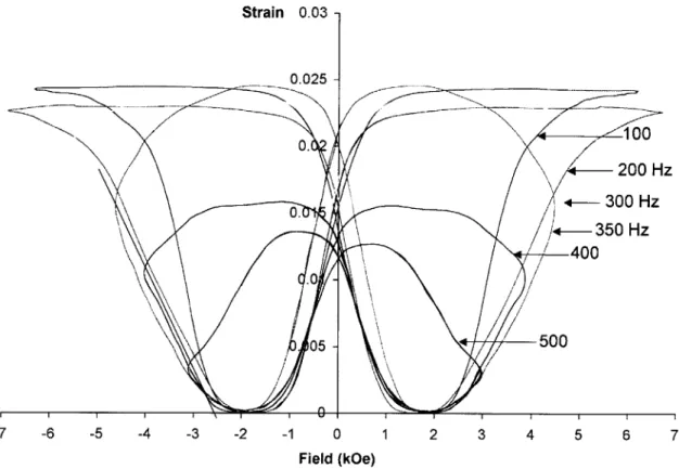
Strain 0.03 -0.025 0. 0. 0-05 -100 200 Hz +-- 350 Hz 400 \% -500 -7 -6 -5 -4 -3 -2 -1 0 1 2 3 4 5 6 7 Field (kOe)
Figure 1-12: High frequency strain versus field response for Henry's actuator system. A prestress of 1.7 MPa was used for these curves. From [11].
0.4 0.3 6 J 0.2 bottom 0.1 0 0 5 10 15 20 25 peak H [kOe]
Figure 1-13: Onset time versus peak magnetic field. tbottom and ttop represent the onset time predicted by the two extreme cases of Figure 1-14. tth is the time it takes the magnetic field to reach the threshold for actuation. From [10].
core Helmholtz coil and a bank of high voltage capacitors to generate magnetic field pulses on the order of 1 T lasting less than a millisecond. He found that the onset time of actuation during these pulses varied within a well defined region (Figure 1-13). The onset time is the time between the magnetic field reaching H0, and the most mobile twin boundary moving
far enough to cause measurable actuation. Marioni found that mass inertia of the crystal was the limiting factor in onset time, and his data was bracketed by models of two situations shown in Figure 1-14. This work indicates that the limiting factor in an FSMA actuator's speed is simply the amount of energy available to move the actuated load. Equation (1.5) gives the expression for the energy available for magnetic actuation. The anisotropy energy of the crystal is the maximum energy available for actuation, which results in an actuator energy density of 1.9 x 10⁵ Jm-3 and a blocking stress of approximately 3.0 MPa.
Using smaller magnetic field pulses, Marioni also studied the energy distribution of pinning sites in the crystals. These pinning sites present obstacles to twin boundary motion that can only be overcome by larger driving forces. The specific crystal tested showed a distribution of pinning sites with energies between 0.55Ku and 0.70 Ku. Stresses between 1.7 MPa and 2.2 MPa would be required to move the twin boundary past these obstacles.
(a) top case (b) bottom case
Figure 1-14: Two theoretical situations in which a single twin boundary is responsible for the onset of actuation. In situation (a) the twin boundary moves downward from the free end of the crystal, and only the the mass already swept by the twin is accelerated. In (b), a twin proceeds from the fixed end of the crystal upward, and the mass of both the swept region and untransformed region must be accelerated. From [10].
n L n (Ln 0 CMS CMu t LnA CMu XLn OCMs op. t
Pinning sites are responsible for the non-zero twinning stiffness, Ctb. In a theoretically perfect crystal, overcoming the twinning threshold stress would cause they entire crystal to transform.
1.3
Motivation for This Work
FSMAs have a lower energy density than thermally actuated SMAs, but much higher band-width. They have a raw output energy density that is comparable to mature active ma-terial technologies like PZT and Terfenol-D. FSMAs produce much higher output strains than PZT or Terfenol-D (6% as opposed to 0.1%), at much lower stress levels. Experiments have shown that the strain and energy density of FSMAs combine to limit FSMA actuation bandwidth to approximately 2 kHz [2]. FSMAs appear to fit into an empty niche in the spectrum of active materials, until the requirement of the magnetic field is considered.
The large magnetic field required, up to 0.8 T to reach saturation magnetization. is not trivial to produce. Electromagnets designed to provide the required field continuously or with duty cycles greater than a few percent must be substantially larger than the volume of the FSMA crystal. Appendix A examines the design of such magnets, and Table 1.2 summarizes the results of the design exercise, along with a comparison to commercially developed Ni-Mn-Ga actuators. Even magnet designs that are only utilized for short pulses of large currents must be large enough to fully envelope the FSMA crystal in the generated magnet field.
In conventional SMAs, heat can be generated by simple resistive heating of the SMA itself, or provided by radiation, conduction, or convection from some source that can be easily distanced from the actuator. Increasing the distance between the FSMA and the magnetic poles results in an increase in the energy and volume requirements for the magnet, both of which scale with the cube of the magnet's gap length. The combined properties of an electromagnet/FSMA actuator, with an effective energy density that is a small fraction of raw material energy density, could make it difficult to find a problem for which FSMAs
are a good solution.
In an attempt to reduce the magnetic requirements for actuation, acoustic vibrations were induced in the Ni-Mn-Ga crystal while it was magnetically actuated [15]. This acousti-cally assisted actuation reduces the threshold field for actuation and increases the strain
Table 1.2: Collected data for commercial actuators available from AdaptaMat compared with optimized electromagnetic designs for identical crystal sizes. Electromagnet design is discussed in Appendix A. Actuator images and data from [14].
FSMA.. Esmtd%
Crystal % Volume Optimized Estimated % Commercial Actuator Dimensions Active Theoretical Volume
Material Design Active
(mm) Material 0.52 x 2.4 x 84 0.55 x 2.2 x 15 15 x 40 x 25 0.14% 0.12% 0.33% 0.30% 0.16% 0.63% A5-2 A06-3 A1-2000
response at a given field. The limits and details of this effect are still being investigated; however, even with a very dramatic reduction in the magnetic requirements, a magnet of some sort will still be required.
The motivation for the work presented in this thesis came from the hypothesis that twin boundary motion could be induced using only acoustic forces. Two possible mechanisms for inducing twin boundary motion using acoustic stress were proposed. The first was to use resonant waves with stress intensities high enough to induce twin boundary motion. When the drive frequency of the waves was varied slightly off resonance, the crystal would change shape so that its new resonance would match the driving frequency. The second was to use asymmetrical acoustic pulses to extend or contract the crystal one pulse at a time.
The first proposed method of acoustic actuation was tested briefly in the apparatus used for acoustically assisted magnet actuation. A piezoelectric stack was used to vibration a small crystal at its fundamental longitudinal resonance with as much power as was available. This resulted in rapid heating of the piezoelectric stack and subsequent heating and trans-formation of the Ni-Mn-Ga crystal to austenite. Whether heating of the crystal was due to conduction from the piezoelectric stack, or whether plastic deformation was partially to blame is unknown [16]. However, this result led to the conclusion that a resonant standing waves (-100 kHz) with stress levels near the threshold stress of Ni-Mn-Ga (1 MPa) might be impossible to realize in the martensitic phase.
The second method proved to be the most plausible route to acoustic shape memory alloy actuation. Generation of suitable compressive or tensile longitudinal acoustic pulses with stresses on the order of 1 MPa proved to be difficult but not impossible. After several design iterations, an experimental device was created that was capable of generating twin boundary motion using acoustic pulses.
The main goal of this work was to understand and characterize acoustic pulse SMA actuation. Experimental results from four different actuators were gathered, under a variety of actuating conditions. The actuators, and the design process that led up to them, are discussed in Chaper 2. Measurements of the electrical input pulses, generated acoustic pulses, and the output stress and strain of the actuator were collected and are presented in Chapter 3. Chapter 4 provides analysis of selected measurements and discusses the affects of various actuation parameters. Finally, Chapter 5 discusses the potential for applications and future work with acoustic pulse SMA actuators.
Chapter 2
Experimental Apparatus
In this chapter, the experimental apparatus used to demonstrate acoustic actuation of FSMA crystals is described. Several design iterations were required to go from working theory to working actuator. Since the design requirements for a working acoustic pulse FSMA actuator were initially unknown, approximate requirements were determined for each iteration, and actuator prototypes were assembled to test the functionality of each design. The functional requirements were updated using the data collected at each iteration, and a new design was developed.
Section 2.1 describes the functional requirements for an acoustic pulse FSMA actuator. Section 2.2 describes the first design prototype, its inadequate performance, and the new design requirements that were developed from the experience gained. The remainder of the chapter describes the four actuators used in collecting the data presented in Chapter 3. The first two of these actuators, CO and C1, were the first two functional designs. Actuator C2 included additional design improvements, as well as new components for actuating against an elastic load. The fourth actuator, C3, incorporated a stress sensor to aid in studying the behavior of the acoustic pulse.
2.1
Functional Requirements
In this section, the functional requirements for each of the components of the acoustic pulse actuator are described. Each of the subsections describes one of the components and the corresponding requirements, except for Section 2.1.2, which is devoted to the finite element simulations that were used to aid in the design of two of the actuator components, as well
as the design of the overall actuator.
2.1.1
Acoustic Pulse Generator
The initial requirements for a functional acoustic pulse actuator were developed using the material properties of Ni-Mn-Ga, from the literature on magnetic actuation (see Chap-ter 1), and linear models of acoustic waves in the actuator system. Many of the functional requirements were revised as experience was gained through experimentation.
The most fundamental requirement on the acoustic pulse FSMA actuator is that the acoustic pulse generator be able to generate shaped transient stress waves, with stresses larger than the twinning stress, ao, in the FSMA. In Ni-Mn-Ga, the generally accepted value of uo is about 1 MPa. Generating a stress of this magnitude statically using magnetic fields is not difficult. However, it is more difficult to generate these stress levels in a transient acoustic wave.
The second requirement is that the magnitude of the actuating stress wave is asymmet-ric, so that when the actuator is being compressed the compressive stress is greater than 0o, and the tensile stress is much less than oO. When the actuator is being extended the tensile stress is greater than o0, and the compressive stress is much less than oO. This requirement
includes stress waves generated directly by the pulse generator, as well as any reflections that develop in the actuator.
The third requirement is not so much a requirement as a goal, namely, that the acoustic pulse actuator is as small as possible. Acoustic pulse actuation was originally conceived to eliminate the need for a bulky electromagnet from magnetic FSMA actuators. Replacing the electromagnet with a bulky pulse generator would not accomplish the original intent.
Due to the high energy densities and blocking stresses available in active material, it was decided that an active material would be used as the pulse generator. Several material technologies are capable of generating a force that can be converted into a 1 MPa stress on the FSMA. In order to maximize energy density, only actuators capable of generating the stress directly (i.e. without mechanical amplification) were considered. Piezoelectric and magnetostrictive materials are the only mature technologies capable of generating stresses higher than 1 MPa [17]. However, magnetostrictive devices are limited to significantly lower operating frequencies than piezoelectric devices, due to the inductive load of the electromagnets they require, and the formation of eddy currents in the magnetostrictive
material. Since piezoelectric devices can be operated at higher frequencies, they can generate actuation level stresses using smaller displacements, and therefore a shorter active material length than a magnetostrictive actuator. In order to determine more specifically what type of piezoelectric device would be required to implement the pulse generator, the results of a simple 1-D finite element simulation were used, as discussed below.
2.1.2 1-D Finite Element Simulation
A one-dimensional lumped mass finite element model was developed to help determine the displacements and pulse durations that might be required to generate actuation stresses in the FSMA crystal. The details of this model are discussed in Appendix B.
In the simulations, it was assumed that a piezoelectric device would be used as the pulse generator. The one-dimensional constitutive law for a longitudinally polarized piezoelectric device is
E33 S3 3 U3 - d33 E3 (2.1)
D3 = d33 U3 + K3 o E3 , (2.2)
where E33 is the longitudinal strain of the device, s3is the material compliance at constant field, U3 is the stress, d3 3 the piezoelectric strain coefficient, E3 is the electric field, D3 is the
charge density, r, is the relative dielectric constant measured at constant stress, and ,o is the permittivity constant of free space [18]. This law provides an easy way to estimate the quasi-static response of a piezoelectric actuator. However, the dynamic response is more difficult to compute, which is why a finite element model was employed. For use in the finite element model, Equation 2.1 is multiplied by the the thickness of the piezoelectric and rewritten as
-s3 O3 t3 = -u 3 + d3 3V , (2.3)
where u3 is the displacement of the piezoelectric device, t3 is the thickness, and V is the voltage across the device. In this form, the equation shows that a positive applied voltage results in a compressive stress on the piezoelectric device, assuming the boundaries do not allow the device to expand. In the finite element model, the boundaries are elastic and the compressive stress propagates into the rest of the system as the piezoelectric device expands.
Table 2.1: Properties of piezoelectric materials used in acoustic pulse actuation experiments.
d33 is the piezoelectric strain coefficient, g33 is the voltage coefficient, Ji is relative dielectric
constant. The quantities listed for the stack are for the entire assembly, not the bulk material of the individual layers. The device were purchased from Piezo System, Inc. [19]
Part Number T140-A4E T11O-H4E TS18-H5-104 Type Single Layer Single Layer Stack Thickness 1.02 mm 0.267 mm 18.0 mm
Stiffness 52 GPa 50 GPa 43 GPa
d33 0.390 nm/V 0.650 nm/V 140 nm/V
g33 24.0 mV-m/N 19.0 mV-m/N 0.16 mV-m/N
T 1800 3800 N/A
K3
Capacitance (5 mmx5 mm) 390 pF 1500 pF 1600 nF
A typical simulation result is shown in Figure 2-1. The left hand side of the piezoelectric was treated as though it were attached to a semi-infinite rod, so that no reflections occur at that boundary. The right end of the FSMA crystal is free. Simulations using the model shown in Figure 2-1(a) were run with a variety piezoelectric thicknesses and pulse durations to determine the magnitude of stresses that could be generated with a single layer piezoelectric device. The results are shown in Figure 2-2.
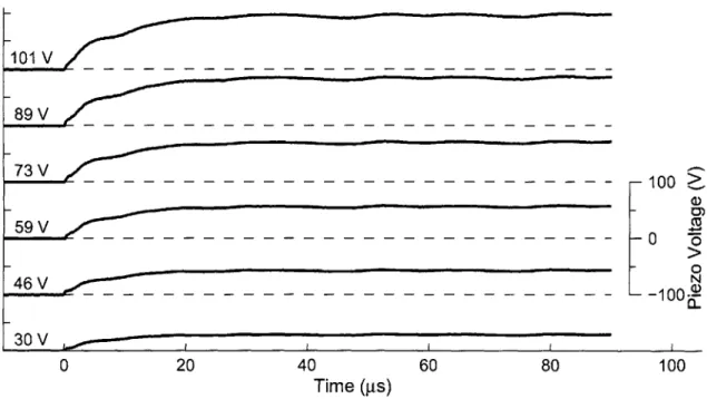
The peak input voltage for all of the results shown in Figure 2-2 was 120 V, which corresponds to a quasi-static displacement of 40 nm. The shape of the simulated input voltage wave was a highly asymmetric sine wave. The high frequency, fH, portion of the sine wave looks like a raised cosine going from 120 V at t = 0 to 0 V at t = 2/fH. This voltage change quickly contracts the piezoelectric device and generates a tensile stress pulse. The low frequency, fL, portion of the input pulse returns the piezoelectric actuator to 120 V, in order to prepare for the next pulse. The waves used in these simulations had an asymmetry of 40:1. The rise time, tr, of the input wave, defined as the time from 10% to
90% of the maximum, can be calculated using the definition of the raised cosine function.
It is approximately equal to
tr = 0.255 fH . (2.4)
of the slow portion of the pulse, fL, can be found using
fL = 0.025 fH . (2.5) The time constant of this portion of the wave, tf, can be calculated identically to tr.
The current required to generate the compressive stresses shown in Figure 2-2(a) can be estimated using Equation (2.2) and the dimensions of the piezoelectric actuator. The charge on the piezoelectric is
q3 d33 F3 + C33 V , (2.6)
and maximum current is
Imax = max dq3 (2.7)
K dtJ
where C33 is the capacitance of the piezoelectric actuator, q3 is the charge, and F3 is the
force. Figure 2-2(b) shows the estimated currents required to generate the stresses shown in Figure 2-2(a). The dotted line in Figure 2-2(b) represents the maximum current output of an M. S. Kennedy 610 amplifier. The MSK610 was the amplifier used during testing of the single layer piezoelectric actuator design, discussed in Section 2.2. The simulation results shown in Figure 2-2 indicate that acoustic pulse actuation using a single layer piezoelectric and the MSK610 might not be possible, since none of the simulations that result in 1 MPa or higher stress fall under the current limit of the MSK610. Testing confirmed this, and showed that the actual stresses induced by the single layer piezoelectric were much lower than the simulated results.
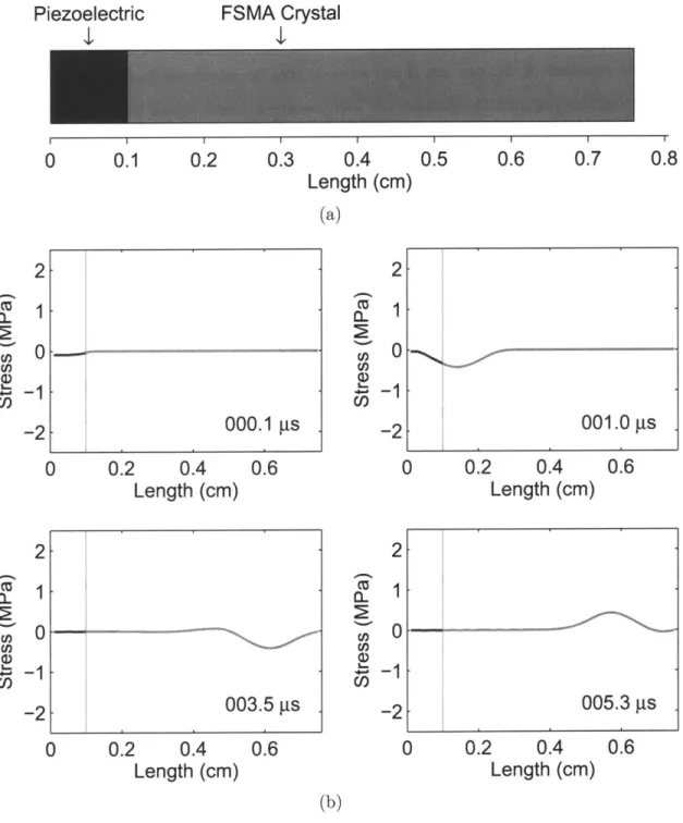
2.1.3 Reflector
One of the functional requirements for the acoustic pulse actuator came from simulation results like those shown in Figure 2-1. The reflection of the stress pulse off the free end of the FSMA results in an inverted stress wave, which could undo the work done by the original actuating stress wave. The brass reflector, in Figure 2-8(a), is in place to prevent this inverse reflected pulse.
Classical wave theory can be used to explain the inversion of the stress pulse reflecting off a free boundary. Wave theory also shows why the addition of a reflector prevents the
Piezoelectric
I1
FSMA Crystal
I.1
I II I0
0.1
0.2
0.3
0.4
0.5
0.6
0.7
Length (cm)
(a)
000.1 Rs
0 0.2 0.4 0.6Length (cm)
2
1
0
0.2
0.4
Length (cm)
0.6
2
CU Cn M) I-(n C,,1
0
-1
-2
2
1
0
-1
-2
001.0 s
)
0.2
0.4
0.6
Length (cm)
005.3 gs
0
0.2
0.4
Length
(cm)
0.6
(b)
Figure 2-1: Simulation of an acoustic pulse FSMA actuator. (a) The model being simulated. The boundary conditions are that the right face of the FSMA is free and the left face of the piezoelectric pulse generator is nonreflecting. (b) Results of the 1-D linear elastic finite element simulation used to estimate the magnitude of stresses that can be generated in the FSMA crystal.
2
0.8
C,, C,,1
01
-2
Cu C,, (D,-1
-2
003.5 gs
I
-41 CD 0n CO U) C a) 1021 11 10 2 10 10 10 10 V V 9 A V 100
Thickness (mm)
(a)
-0-- 4.0 MHz 2.0 MHz 1.0 MHz -U- 0.5 MHz 4 0.2 MHz --- 250 mA Limit...--1 100 Thickness (mm)
(b)
Figure 2-2: A collection of maxima from a series of simulations. (a) The maximum generated compressive stress taken from the midpoint of the crystal, plotted for several frequencies,
fH. (b) The peak current required to generate the stresses shown in (a). 10 - 4.0 MHz ---- 2.0 MHz 1.0 MHz 0.5 MHz a + 0.2 MHz _0 a) $D C 2) 100
-V
Table 2.2: Acoustic impedance for selected material.
inverted pulse. In setting up the wave equation to study reflection off the boundary between two materials, we will assume our system consists of two infinitely long rods of identical cross-section, meeting at x = 0. A longitudinal wave propagates through the left hand rod from -oc and into the right hand rod. Assuming that stress and displacement are
continuous across the boundary at x = 0, the solution to the wave equation is
A(eikx-iwt + Re-ik-iwt) for x < 0 (2.8)
TAeik2x-iwt for x > 0 where ____- _1 R = Y2P2 (2.9) Yipi +1 Y2
p
2 T= 1+R, (2.10) k = w ,(2.11)
k2 =w . (2.12) y2The quantity
VFp,
referred to as acoustic impedance, is the material property that defines the behavior of the wave at the material boundary. See Table 2.2 for acoustic impedance values of selected materials. We will examine three combinations of materials, which result in three different wave behaviors at the boundary.In the first combination, the material in the left hand rod has high acoustic impedance Material Specific Acoustic
Impedance Brass 29 MPa.s/m Ni-Mn-Ga 15 MPa-s/m Steel 40 MPa-s/m PZT 5A 20 MPa-s/m Aluminum 14 MPa-s/m Titanium 22 MPa.s/m Glass 12 MPa-s/m Epoxy 2.1 MPa-s/m
and the material in the right hand rod has low impedance. In this case, the displacement wave reflected from the boundary has the same sign as the incoming wave. However, because it is traveling in the opposite direction, the stress caused by the wave has the opposite sign. The equation for the stress wave can be obtained by taking the first derivative of Equation (2.8) with respect to x, which results in
U/
f
ikjA(eikjx-iwt - Re-iklx-iwt) for x < 0 (2.13)ik2TAeik2x-iwt for x > 0
In this first combination, the displacement amplitude of the transmitted wave is larger than both the incoming and reflected waves. Because the right hand rod has low acoustic impedance, the power of the transmitted wave is still smaller than the power of the incoming wave. As the impedance of the right hand rod approaches zero, the displacement amplitude of the transmitted wave approaches twice that of the incoming wave, but the energy of the transmitted wave approaches zero. The amplitude of the reflected wave approaches that of the incoming wave. However, the reflected and incoming stress waves have opposite signs. The inverted reflection is caused by the zero stress condition at the material boundary, which is essentially free when the impedance of the right hand rod is zero. The finite element simulation, in Figure 2-1, shows this behavior for a wave of very short duration.
In the second combination, the two materials have the same acoustic impedance. In this situation the reflected wave vanishes and the magnitude of the transmitted wave is identical to the incoming wave.
In the third combination, the left hand rod has a lower impedance than the right hand rod. In this case there again a reflected wave; however the reflected stress wave now has the same sign as the incoming stress wave. The brass reflector in Figure 2-8(a) sets up the third combination at the right hand end of the FSMA crystal. The reflected stress pulse will thus have the same sign as the actuating stress pulse and will not interfere with the work that is done by the actuating pulse. The large size of the reflector is meant to allow the wave to disperse before it reflects off the free end of the brass and returns to the FSMA. Attempts to optimize the shape of the reflector will be discussed in the next section.
2.1.4
Acoustic Horn Dissipator
While the brass block reflector used in the single layer actuator experiments prevents an inverted reflection from the end of the FSMA, there is still an inverted reflection from the end of the brass block. In order to minimize this reflection, an attempt was made to design a reflector shape that would disperse the reflection before it returned to the FSMA crystal. The design was carried out using a one-dimensional finite element model similar to the one mentioned in Section 2.1.2. However, the model was rewritten using conservative elements. The conservative element model was an improvement over the lumped mass model, and was found to closely match 1-D analytical solutions to the wave equations for simple shapes such as a straight rod and an exponentially thinning rod. See Appendix B for the comparison and derivation of these models.
Starting from an exponentially thinning horn, shown in Figure 2-3(a), MATLAB's fminimax routine was used to change the shape of the horn in an attempt to find a more dispersive shape. When MATLAB was allowed to vary size of the individual elements, an immediate problem became apparent. As Figures 2-3(b) and 2-3(c) show, the optimization favored the formation of reflectors using sharp changes in the horn's cross-sectional area. The resulting reflectors would exhibit different behavior in 3-D space than they do in the 1-D model. This optimization problem can be avoided somewhat by constraining the op-timization, or by varying a parameterized function that describes the shape of the horn, rather than varying the size of the individual elements. After a wide variety of constraints and parameterizations were tried, a few possible horn candidates emerged. However, their performance (Figure 2-3(d)) was only marginally better than that of a block (Figure 2-3(e)) similar to the reflector already used. Because 3-D effects made the potential performance of the optimized horns questionable, the simple block reflector was used in all the apparatus in this thesis.
2.1.5 Bond Lines
One of the implicit requirements of the acoustic pulse actuator design is that the connections between the various pieces of the actuator must not separate during normal actuation. Also, in order to satisfy the first functional requirement of the acoustic pulse actuator, the connections must transmit the actuating pulse from the pulse generator to the FSMA and
D 0 2? 0 ) -1 --40 -20 0
Time
20 40-1
0
1
2
Length
(a)
Max Inverted a
=0.29
C,)0
-1
.
-40 -20 0Time
20 402
3
-1
0
1
Length
(c)
-40 -20 0Time
20 40-4 -2
0
2
4
6
Length
(b)
Max Inverted a
=0.23
0 0 -I
-40 -20 0Time
0
2
Length
(d) 20 404
Max Inverted a= 0.33
U) 1 Cl) -40 -20 0Time
-10
0
Length
20 4010
(e)Figure 2-3: Potential dispersive horn designs. The stress plots in these figure show the reflection of a gaussian stress pulse with a magnitude of +1. The horn models are shown in profile, and have a thickness of 1. All dimensions are normalized about the unit pulse, and unit cube (darker square).
C,)
C,)
Max Inverted a = 0.55
Max Inverted (; = 0.34
Figure 2-4: SEM images of epoxy bonds on aluminum. The bonds were prepared using the same cleaning and clamping techniques as used with materials glued together in the experimental apparatus.
into the reflector. Because of the sensitivity of Ni-Mn-Ga's actuation properties to changes in composition and heat treatment, metal-metal bonding was ruled out. Polymer adhesives, other than the heat curing variety, do not have any adverse affects on the FSMA. However, the maximum strength of adhesive bonds is only -30 MPa, under ideal conditions.
The bond thickness of any polymer bonds in the actuator is important because of the effect thickness has on transmitting acoustic pulses between the other materials. A thinner bondline, while more susceptible to failure, also has a much smaller affect on transmission of acoustic waves. Finite element modeling indicated that bondlines thicker than 50 pm had a detrimental affect on wave propagation. In order to estimate the bond thickness of actual bondlines, dummy bonds were prepared using Loctite E-120HP epoxy and alu-minum. E-120HP is one of the adhesives used in two of the acoustic pulse actuators. The same surface preparation and clamping techniques used when assembling the acoustic pulse actuators were used when assembling these dummy bonds. After the dummy bonds cured, they were examined in a scanning electron microscope, which showed that the bondlines were no thicker than 20 ym, as shown in Figure 2-4. By keeping surfaces flat, roughness low, and using consistent clamping forces, bonds with similar thickness were consistently achieved in the experimental actuators.
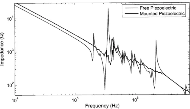
Conductivity is another important factor in adhesive bonds. In the single layer piezoelec-tric actuator apparatus, the piezoelecpiezoelec-tric was grounded through its bond to a steel backing. Although conductive adhesives were not used due to their low strength, conduction across a thin bondline was achieved, thanks to the surface roughness of the mating parts. DC measurements and impedance data over a wide range of frequencies (100 Hz to 40 MHz), indicated that the resistance of E-120HP bonds varied from assembly to assembly, but was never above 1 Q. While good conductivity was necessary in the single layer piezoelectric
actuator, it caused measurement noise in other apparatus if insulators were not employed to electrically isolate sensors.
2.1.6 Drive Circuit Design
The electronics that drive the acoustic pulse generator are just as important as the active material used. Section 2.1.2 mentioned briefly the MSK-610 amplifier, which was used to drive the single layer piezoelectric actuator. The MSK-610 has a full power bandwidth of 9 MHz. However, its current limit of 200 mA hindered actuation of the single layer piezoelectric pulse generator at high bandwidth. Using multiple amplifiers in parallel could have improved the single layer actuator. However, a much more drastic improvement was necessary to get stress levels near c-o.
A piezoelectric stack actuator, TS18-H5-104, replaced the single layer. The stack's capacitance is much higher than a single layer, so it draws much higher currents. In order to drive the stack from 0 V to 100 V with a rise time of 10 1us, a current of 16 A is required. A special circuit was designed to generate a sawtooth wave using two MOSFET switches to control the rise and fall of the waveform. Figure 2-5 shows the first design iteration of the circuit. Designated EO, this circuit was used in the first funtional acoustic actuation experiments, but did not perform as well as desired. Circuit El (Figure 2-6) is a redesign of the original circuit with a maximum burst current of approximatively 40 A, which results in a rise time of 4 ps for driving the piezoelectric stack to 100 V.
Circuits EO and El function almost identically. To generate compressive pulses, a con-stant voltage at the gates of the low power p-type IRFU9310 MOSFETs allows any charge on the piezoelectric stack to slowly and continuously drain to ground. A square pulse on the gates of the higher power IRF820 MOSFETs force the piezoelectric stack to quickly charge up to 100 V, causing it to expand rapidly and generate a compressive stress pulse. As soon as the triggering pulse to the IRF820s subsides, the charge drains off the stack, and it returns to its original state. The relay in circuit El allows the circuit to be switched between compressive and tensile pulses. To generate tensile pulses, the stack is first charged to 100 V and then quickly discharged, contracting the stack and creating an tensile pulse.
Some control over the generated stress pulse is possible through the electronics. The voltage of the power supply, Vin, and the triggering pulse, Vg, affect the amplitude and lead-ing edge slope of the sawtooth wave. The amplitude of the sawtooth wave is approximately