Design and Engineering of Low-Cost Centimeter-Scale Repeatable and Accurate Kinematic Fixtures for Nanomanufacturing Equipment Using Magnetic Preload and Potting
by MASSACHUSETTS OF TECHNO Adrienne Watral
MAY 1 8
S.M. Mechanical EngineeringMassachusetts Institute of Technology, 2010
LIBRAR
Submitted to the Department of Mechanical Engineering in Partial Fulfillment of the Requirements for the Degree of
Master of Science in Mechanical Engineering at the
Massachusetts Institute of Technology
ARCHIVES
December 19, 2010
@ 2010 Massachusetts Institute of Technology All rights reserved.
Signature of A uthor ... ... ...
eprtmen omechanical Engineering December 19, 2010
Certified by . . ... ..
L....
....
C
A ociate P fessor of Mechanical Engineering
fon
Thesis SupervisorA ccepted by ... ... . . David E. Hardt Professor of Mechanical Engineering Graduate Officer
INSTITUTE
LOGY
2011
Design and Engineering of Low-Cost Centimeter-Scale Repeatable and Accurate Kinematic Fixtures for Nanomanufacturing Equipment Using Magnetic Preload and Potting
by
Adrienne Watral
Submitted to the Department of Mechanical Engineering on December 19, 2010 in Partial Fulfillment of the Requirements for the Degree of Master of Science in
Mechanical Engineering
ABSTRACT
This paper introduces a low-cost, centimeter-scale kinematic coupling fixture for use in nanomanufacturing equipment. The fixture uses magnetic circuit design techniques to optimize the magnetic preload required to achieve repeatability on the order of 100 nanometers. The fixture achieves accuracy to within one micrometer via an adjustable interface composed of UV curing adhesive between the mating kinematic coupling components. The fixture is monitored by a micro-vision system and moved by a six-axis nanopositioner until proper alignment is achieved, at which point the fixture position is permanently set by UV light. This thesis presents design rules and insights for design of a general accurate and repeatable kinematic fixture and presents a case study of fixtures used for tool exchange on dip pen nanolithography machines. A prototype fixturing assembly was fabricated and tested for repeatability and stability in six degrees of freedom. The test results concluded that the fixture has a 1-o- 3-D translational repeatability of 87 nanometers and a 3-D stability of 344 nanometers over 48 hours. This is an order of magnitude improvement on past low-cost accurate and repeatable fixture designs. This optimized accurate and repeatable kinematic fixture will enable repeatable, accurate, quick, and elegant tool change, thus advancing the manufacturing capabilities of nanofabrication techniques.
Thesis Supervisor: Martin L. Culpepper
ACKNOWLEDGEMENTS
First and foremost, I would like to thank my thesis advisor, Professor Martin Culpepper. He has been a wonderful mentor to me and has taught me mechanical design at a very deep level. I greatly appreciate all his help through the course of this thesis. Marty was supportive of me during a very difficult year and picked up my slack after I broke my back and was unable to do much hands-on work for a few months. Thanks for everything, Marty.
I would like to thank NanoInk for providing me the financial support for the first two semesters of my Master's program. NanoInk also provided the functional requirements and constraints for the project and allowed me to use their DPN 5000 machine on multiple occasions.
I would like to thank all of my friends and family who supported me during the course of my Master's program. Thanks to my fellow PCSL students, especially Maria Telleria. You were a great group of people to work with. I would like to thank my parents for their continual support for all of my endeavors.
I would like to thank Bill Buckley of the Laboratory for Manufacturing and Productivity for always being happy to help out in the machine shop.
Finally, I would like to thank Ian Wolfe. Ian has done more for me the past year and a half than anyone, and I would not have been able to finish this thesis without his love and support.
CONTENTS
Contents
A bstract ... 3
A cknow ledgem ents ... 5
Contents ... 6 Figures... 9 Tables ... 14 Chapter 1: Introduction ... 15 1.1 Introduction to Research... 15 1.1.1 M otivation... 17 1.2 Thesis Organization ... 21
1.3 Know ledge and Technology Gap ... ... 22
1.3.1 Com parison of Com m on Fixturing M ethods ... 22
1.3.2 Historical Perspective on Accurate and Repeatable Fixturing... 26
1.4 Chapter Sum m ary ... 29
Chapter_2: D esign R equirem ents ... 31
2.1 Dip Peng p y ... . 31
2.2g q ... 37
2.3 Kinematic Fixtures: General Concept ... 38
Chapter_3: R epeatability ... 42
3.1 D efinition and Im portance of Repeatability ... 42
3.2 K inem atic Coupling Design... 45
3.3 Error...48
3.3.1 Friction...49
3.3.2 Other Error Sources... 52 3.4 Preload...
3.4.1 M agnetic Preload... 55
3.4.2 Contact M echanics ... 55
3.5 M agnetic Circuit Design... 57
3.5.1 M agnetic Circuit M athem atical M odel ... 59
3.5.2 M agnetic Circuit M odeling in FEM M ... 64
3.5.3 M agnetic Shim ... 67
3.6 Lessons learned/design rules/insights... 69
Chapter_4: A ccuracy... 71
4.1 D efinition and Im portance of A ccuracy ... 71
4.2 M ethods for achieving accuracy ... 73
4.2.1 Potting in U V Curing A dhesive ... 74
4.2.2 Plastically D eform ed Flexures ... 74
4.2.3 A djustable K inem atic Coupling ... 75
4.3 Chosen M ethod: System Overview ... 75
4.3.1 V ision System ... 77
4.4 Potting... 79
4.4.1 Overview of Potting ... 79
4.4.2 Chemistry of Ultraviolet Adhesives ... 81
4.4.3 Selecting a Light Source ... 83
4.4.4 TypesofU V A dhesives ... ... 85
4.4.5 Testing of A dhesives... 87
4.4.6 Lessons learned/design rules/insights: ... 90
Chapter 5:_Case Study: Dip Pen Nanolithography Tool Changing ... 92
5.1 Project Introduction ... 92
5.2 Current Procedure ... 96
5.3 Overview of Fixture D esign... 97
5.3.1 Review of m ajor requirem ents ... 97
5.3.2 Fixture D esign... 100
5.3.3 D evice Fabrication ... 106
5.4 V alidation... 108
5.4.2 Experim ental Results... 111
5.4.3 D iscussion of Results ... 120
C hapter 6: C onclusions ... 122
6.1 Recap of Research Objectives ... 122
6.2 Research A ccom plishm ents ... 123
6.3 Future W ork ... 125
6.3.1 Flexural Elem ents... 125
6.3.2 A utom ation... 126
6.3.3 M odeling Shrinkage ... 126
6.3.4 Refine M agnetic M odel... 126
R eferences... 127
A ppendix A : K C D esign Spreadsheet ... ... ... ... 127
A ppendix B : Force and D isplacem ent Solutions... 127
Appendix C: Hertzian Contact Stress Analysis ... 127
Appendix D: Dymax OP-4-20632 Series UV Adhesive Data Sheet ... 127
A ppendix E : DPN 5000 System D ata Sheet ... 127
FIGURES
Figure 1.1: Accurate and repeatable kinematic fixture prototype mounted to a universal
scanner mount of a DPN machine ... 15
Figure 1.2: Accurate and repeatable kinematic fixture CAD model exploded view ... 16
Figure 1.3: Traditional three groove kinematic coupling ... 24
Figure 1.4: Cost vs. repeatability comparison of coupling technologies... 26
Figure 1.5: KC modified with flexural hinges on the ball side to improve the repeatability by reducing friction. The entire KC is shown in (a), and a close up of the ball flexures are show n in (b). ... 27
Figure 1.6: a. Prototype (groove side removed for clarity). b. Adjustable KC joint... 28
Figure 2.1: DPN Schematic: molecules are transported from the AFM tip to the substrate via capillary transport ... 31
Figure 2.2: Probe holder used for positioning the tip onto the DPN machine... 34
Figure 2.3: Mounting block used for securing tip into probe holder in closed (a) and open (b) positions... 34
Figure 2.4: Mounting of tip into probe holder ... 35
Figure 2.5: Universal mount on DPN machine, used for alignment of tip assembly. Magnets and alignment guides are shown (a) as well as the tip assembly placement (b) .... 36
Figure 2.6: Accurate and repeatable kinematic fixture CAD model exploded view ... 39
Figure 2.7: Ball side of the KC, showing the clearance between the balls and the holes to allow for position adjustm ent ... 39
Figure 2.8: Assembly station CAD model, including vision system, nanopositioner, UV lights, and m aster KC fixture ... 40
Figure 3.1: Target analogy for repeatability and accuracy ... 43
Figure 3.2: Cost and repeatability comparison for alignment mechanisms... 44
Figure 3.3: Three-groove kinematic coupling ... 46
Figure 3.4: Kelvin kinematic coupling... 47
Figure 3.5: Ball and groove layout for optimal stability (Slocum, Precision Machine Design, 1992)... 48
Figure 3.6: The effect of surface asperities on coupling... 49
Figure 3.7: KC modified with flexural hinges on the ball side to improve the repeatability by reducing friction. The entire KC is shown in (a), and a close up of the ball flexures are show n in (b). ... 50
Figure 3.8: Ball in KC vee-groove modified with elastic hinges... 51
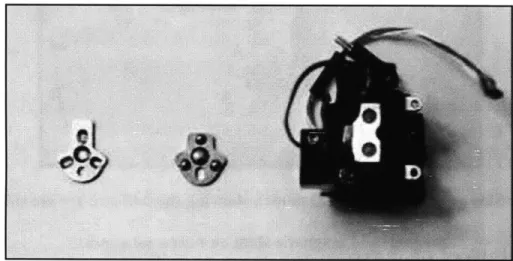
Figure 3.9: KC fixture ball and groove components aside DPN machine universal mount. The groove side of the KC is held onto the universal mount by the two small Alnico m agnets in the m ount...57
Figure 3.10: Side view of fixture CAD model, showing the ball and groove sides, preload magnet, and magnetic shim on universal mount ... 58
Figure 3.11: KC magnetic circuit model. The large air gap provides a large resistance in the flux loop that decreases the magnetic force... 60
Figure 3.12: KC magnetic circuit model with shim. The air gap is reduced and the m agnetic force increased ... 60
Figure 3.13: FEMM magnetic flux density plot for aluminum grooves model... 65
Figure 3.14: FEMM magnetic flux density plot for steel grooves model... 66
Figure 4.1: Accuracy and repeatability target analogy... 71
Figure 4.2 (Culpepper): Generic concept for adjustable interface in the context of a two-axis error calibration. The probe assembly was originally placed with translation error f1 and rotation error z2 (A). Probe tip error is measured via vision system and then adjusted via actuators (B). Improved alignment post calibration and fixation (C). The probe assembly is then ready for accurate alignment into machine... 73
Figure 4.3: KC fixture assembly station ... 77
Figure 4.4: Vision system hardware components set-up... 78
Figure 4.5: Light Spectrum. UV light ranges from approximately 200 to 400 nm in w avelength (htt)... 82
Figure 4.6: KC fixture assembly station. Three UV lights arranged to maximize area of adhesive exposed to light... 85
Figure 4.7 Assembly configured to test various adhesives, consisting of a thin steel plate on top of an aluminum block. Adhesive was applied to each of four corners (a). The assembly is placed under UV light for curing (b)... 88
Figure 4.8: Capacitance probe measurement set-up (a) and Light & electricity protection box (b)...89
Figure 4.9: Dymax 0.2% shrinkage glue stability over 48 hours test results... 90
Figure 5.1: CAD model of fixture on scanner universal mount ... 93
Figure 5.2: NanoInk DPN 5000 machine ... 93
Figure 5.3: DPN 5000 scanner universal mount with magnets and alignment guides for m ounting the tool... 94
Figure 5.4: Laser positioned accurately on tip, verifying that the fixture provides accurate
and repeatable alignm ent... 95
Figure 5.5: Laser spot locating the tip of the tool... 97
Figure 5.6: Fixture groove side mounted to DPN 5000 universal mount ... 99
Figure 5.7: Fixture ball and groove sides with DPN 5000 universal mount... 99
Figure 5.8: KC magnetic circuit model. The large air gap provides a large resistance in the flux loop that decreases the magnetic force... 101
Figure 5.9: KC magnetic circuit model with shim. The air gap is reduced and the magnetic force increased... 102
Figure 5.10: Alignment guides on the back side of the groove mount; three points kinematically locate the groove mount to the edges of the universal mount... 103
Figure 5.11: DPN 5000 universal mount magnets and alignment guides for mounting the tip ... 104
Figure 5.12: Fixture ... 105
Figure 5.13: Ball and groove sides of the KC fixture ... 107
Figure 5.14: Magnetic shim cut from 0.41 mm 17-7 PH stainless steel... 108
Figure 5.15: Fixture repeatability and accuracy validation set-up. The groove side of the KC is rigidly mounted to a plate that is bolted to an air table (left) and the ball side is rigidly mounted to a preload weight (right)... 109
Figure 5.16: Capacitance probe arrangement for repeatability and accuracy validation. 110 Figure 5.17: Experimental set-up ... 111
Figure 5.18: X-axis repeatability measurements... 113
Figure 5.20: Y-axis repeatability measurements... 114
Figure 5.21: Oy-axis repeatability measurements... 114
Figure 5.22: Z-axis repeatability measurements... 115
Figure 5.23: 0z-axis repeatability measurements ... 115
Figure 5.24: 3-D translation repeatability measurements... 116
Figure 5.25: X-axis stability measurements... 117
Figure 5.26: 0z-axis stability measurements ... 117
Figure 5.27: Y-axis stability measurements... 118
Figure 5.28: 0y-axis stability measurements... 118
Figure 5.29: Z-axis stability measurements... 119
Figure 5.30: 0z-axis stability measurements ... 119
Figure 6.1: Accurate and repeatable kinematic fixture prototype mounted to a universal scanner mount of a DPN machine ... 123
TABLES
Table 1.1: Fixture 1-a and 3-a Repeatability Summary... 16
Table 1.2: Fixture 48-Hour Stability Summary ... 17
Table 1.3: Functional Requirements and Constraints... 29
Table 2.1: DPN Features and Highlights ... 32
Table 2.2: Functional Requirements and Constraints... 37
Table 3.1: Pugh Chart Comparison of Preload Concepts... 54
Table 3.2: Preload force and stick-on force compared for steel grooves, aluminum grooves, and aluminum grooves with a steel shim ... 67
Table 4.1: Comparison of Adjustable Interface Concepts... 76
Table 5.1: Functional Requirements and Constraints... 98
Table 5.2: Preload force and stick-on force compared for steel grooves, aluminum grooves, and aluminum grooves with a steel shim... 107
Table 5.3: 1-a and 3-a Repeatability Summary ... 116
T able 5.4: Stability Sum m ary ... 120
CHAPTER
1
INTRODUCTION
1.1 Introduction to Research
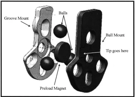
The purpose of this research was to generate the knowledge, technology, and methods required to engineer potted joints that yield cm-scale fixtures with 1 micron accuracy and 100 nanometer repeatability. This research includes the design and fabrication of an adjustable kinematic fixturing system, the construction of a micro vision system that identifies alignment errors in each fixture and automatically adjusts them for proper alignment, and the development of a specific UV cure potting process to permanently set the fixture in an accurate, calibrated, and stable position. Additionally, this thesis provides the general design rules and methods necessary to create small scale kinematic fixtures with desired accuracy and repeatability. Figure 1.1 shows the fabricated kinematic fixture, and Figure 1.2 shows an exploded CAD model.
Figure 1.1: Accurate and repeatable kinematic fixture prototype mounted to a universal scanner mount of a DPN machine
Groove Mount
Figure 1.2: Accurate and repeatable kinematic fixture CAD model exploded view
The fixture was measured to have a 1- a three-dimensional translational repeatability of 93 nanometers. The accuracy of the fixture was measured by a stability test since the fixture was individually calibrated and positioned; error in accuracy then come primarily from
displacement of the adjustable fixture interface, which is measured by displacement over time. The stability of the fixture was monitored over a 48 hour time period and the total
displacement after 48 hours was measured. The greatest error occurs in the z direction and was measured to be 876 nanometers. The fixture repeatability is summarized in Table 1.1 below, and the accuracy/stability is summarized in Table 1.2.
Table 1.1: Fixture 1-a and 3-a Repeatability Summary
X(sm) Y(pm) Z(stm) Ox(ptrad) Oy (ptrad) 0z (prad) 3D(sm)
a 0.107 0.092 0.120 10.3 22.0 11.0 0.093
3a 0.321 0.276 0.360 30.8 66.0 33.2 0.279
Ball Mount
Table 1.2: Fixture 48-Hour Stability Summary
1.1.1 Motivation
This work is important because it allows for a low-cost means to align parts and tools in instruments and equipment for nano-scale research and nanomanufacturing. Reliability, rate, cost, quality, and flexibility of a manufacturing process depends on the ability to effectively position tools and parts with the exact location of such tools and parts being known. Fixturing technology enables a fabrication process to become a manufacturing process by enabling rapid, frequent positioning and part and tool changeovers. Accurate, repeatable, and quick interchange of parts within various nanomanufacturing systems is important, as it allows for improved alignment and positioning of parts and tools with respect to relevant equipment, thus improving reliability, rate, quality, cost, and flexibility.
In order to practice lean manufacturing, a manufacturing business must be able to rapidly and accurately changeover machines and equipment. The most effective way of doing this is by reducing machine set-up time. Indexable tools and fixturing technologies have greatly simplified and improved the changeover process (1).
Upcoming manufacturing processes at the small scale require fixturing capabilities that are beyond the limits of conventional coupling methods. Achieving better precision at a lower cost
has posed a challenge, and so far there is not a fixturing system that can achieve the strict repeatability requirements that small-scale manufacturing processes call for. Various mechanical couplings exist with their distinct advantages and disadvantages compared later in this chapter; however, none of these couplings sufficiently meet all of the requirements of nanomanufacturing processes on their own. Thus a new fixturing technology is necessary.
The impact of this research is a general technology that improves (i) rate, cost, quality, and flexibility in nanomanufacturing & (ii) quality and speed of measurement in instruments and research. The impact of this research will be to fill the fundamental gap - fixturing technology
-that would block the adaptation of small scale fabrication equipment to manufacturing applications. Additionally, this fixturing technology will improve rate and reliability in current low volume fabrication processes, therefore advancing research in the area of small-scale manufacturing.
The specific fixturing technology developed in this thesis, shown in Figure 1.1, was built to be integrated into a dip pen nanolithography (DPN) machine. The fixture is used on the machine to enable rapid accurate and repeatable tool placement and exchange. Chapter 5 presents a case study which evaluates the need for the fixture in the current DPN tool changing process, lays out the specific customer requirements for the fixture in combination with the machine, as well as
detailing the use of the fixture with the DPN machine.
Past research has been done with the goal of accurate and repeatable kinematic fixtures (see Chapter 1.3), however the solution of this research is unique. The accuracy and repeatability of
the fixture designed in this thesis are achieved via the distinct combination of potting and magnetic preload, which will be discussed in detail in Chapters 3 and 4, respectively.
Achieving accuracy with a kinematic coupling requires calibration. The calibration will be achieved by the design and fabrication of a micro-vision and micropositioning system that will allow for errors between actual and desired probe tip position to be identified and corrected. After adjusting any misalignment, the fixture will be permanently set by a UV-curing epoxy in an accurate, stable, and calibrated position. An accurate and repeatable alignment and fixturing system allows for improvements in rate, quality, and reliability of accurately attaching tools to relevant equipment. It also establishes limits for alignment capacity, as well as accuracy and repeatability limits for tool change fixtures. Additionally, this research helps determine a relationship between fixture design, added cost, quality of alignment, and tool change rate. The general kinematic coupling fixturing design can be used to generate custom fixtures, calibration equipment, and calibration processes. Such a fixturing system will advance the automation in small scale manufacturing processes, thus leading to benefits in cost, rate, quality, and flexibility.
In addition to solving the problem of accuracy in kinematic couplings, this research is also unique in that the kinematic fixtures designed are at a small scale. Research in fixture design at the small scale must be directed toward the inherent differences in the engineering science and implementation at the small scale from those at the macro scale. Large-scale principles and practices do not necessarily work at the small scale due to differences in the dominant physics, thermal and material considerations, and manufacturing capabilities. Due to these differences, there must be a shift in the way machines and processes are thought about at the small scale,
including the engineering design principles and analysis, as well as the practical manufacturing and use considerations.
In order for a manufacturing process to succeed it is necessary to be able to move tools and relevant equipment with respect to each other and to know their exact location. This requires highly repeatable precision fixturing technologies. In large-scale machine design, the engineering and physics are well-known; however, very few precision engineers work on the engineering principles and practices at the small scale, thus current fixturing technologies are not sufficient for small-scale machines and processes. In order to progress in the field of small-scale manufacturing, further knowledge about the differences between large and small-scale machines is required. This includes investigation into the differences in the dominant physics at the micro and nano scales from the macro scale, fabrication and manufacturing considerations, as well as concerns arising from thermal variations. Large-scale design principles cannot necessarily be applied to small-scale machines. This research provides insight and design rules pertaining to how to design fixtures for small-scale processes, allowing the reader to better understand the philosophical and practical differences between large and small-scale design.
The fixturing technology developed in this thesis can be implemented in a variety of small-scale fabrication or manufacturing systems as a method of improving rate, quality, cost, and flexibility. This thesis is based on a fixture designed for use in DPN, which is currently a low-volume fabrication process. The addition of accurate and repeatable fixturing technology allows the possibility for DPN to become a high-volume manufacturing process.
1.2 Thesis Organization
The first chapter in this thesis provides the reader with a brief history and comparison of common mechanical fixturing methods. This is important information for selecting the best method for the small scale accurate and repeatable fixtures developed in this thesis. The second chapter introduces the reader to the dip pen nanolithography process that these fixtures were designed to work with, as well as detailing the need for a new fixturing method. Chapter two goes on to describe the design requirements of the fixture and how these were met and an overview of the kinematic fixture design. The third chapter addresses the importance of repeatability and how repeatability is achieved in this fixture via exact constraint design, magnetic preload, and manufacturing techniques for surface finish. The fourth chapter discusses the need for accuracy and how potting can be used to achieve accuracy on the order of 1 micron. Chapter 4 discusses the chemistry and curing process of the adhesive used in the potting and the characteristics based upon which it was selected as a method of achieving accuracy. The fifth chapter presents a case study of the fixture that was designed specifically for use with Nanolnk's DPN machines as a method of improving rate and reliability in low to moderate volume DPN experiments. Chapter 5 also provides the reader with validation of the fixture design with repeatability and stability testing results. The thesis concludes with a discussion of future work and future applications.
1.3 Knowledge and Technology Gap
Many methods of alignment and fixturing exist, all with various advantages and disadvantages. None of which by themselves are sufficient to meet the requirements of accuracy and repeatability in small scale manufacturing applications. The following section discusses a number of these fixturing techniques, including design principles, how they work, and potential benefits as well as shortcomings in the category of accurate and repeatable fixturing for small
scale manufacturing.
1.3.1 Comparison of Common Fixturing Methods
The pin-in-hole alignment method is a non-exact constraint method frequently used for low-cost and easy alignment. Two parts are mated together by pins that fit into corresponding holes or slots. Though the pin-in-hole method is simple and low-cost, it is not sufficient for precision fixturing. These joints are generally sized on the order of inches, with repeatability on the order of tens of microns (2) (3) (4). The performance of pin-in-hole joints is unpredictable, as it is dependent on a number of geometric variables, including the diameters, straightness, parallelism, cylindricity, and distance between the pins and holes. If clearance exists between the diameter of the pin and hole, the location of each component relative to the other is not exactly defined, thus reducing the repeatability. For precision applications, this clearance has to be strictly controlled, thus leading to additional manufacturing costs and increased difficulty in assembly. Pin-in-hole joints are highly susceptible to wedging and jamming, leading to increased assembly time and
damaged parts, thus reducing productivity and increasing costs. The pin-in-hole approach is non-deterministic and repeatability and stiffness are difficult to analyze or predict, so these parameters must be measured experimentally. There are many drawbacks to the pin-in-hole method: tight manufacturing tolerances, binding and jamming, holes slightly larger than pins reduces repeatability and stiffness (2).
Elastic averaging is another common alignment method. Common fixturing methods based on elastic averaging include tapers, rail and slots, collets, and press fits. This method is useful in applications that require high joint stiffness and load capacity and well as in applications where sealing interfaces are necessary. Elastic averaging is based on geometrically over-constraining the mating parts. This over-constraint leads to problems with repeatability, specifically that the tight fit is usually disrupted after repeated use as the surface wears away. Thus repeatability
decreases with increased use and surface wear (3).
Kinematic couplings are a reliable, simple, and inexpensive means of linking systems with high repeatability. The design of a kinematic coupling is deterministic in that for every degree of freedom to be constrained there is a point of contact (4) (5) (6) (7). The potential for repeatability on the order of tens of nanometers makes the kinematic coupling a principal candidate for precision applications. Traditionally, kinematic couplings have been made with three balls that contact six points which restrict motion in six degrees of freedom. These contact points can either be in the form of three grooves or one groove, one tetrahedral socket, and one flat surface. These six contact points create high Hertzian stresses at each point, so care must be taken to
ensure that the contact surfaces can withstand the high stresses and to prevent brinelling beneath the surface of the contacts. A traditional kinematic coupling is shown in Figure 1.3 (4).
Figure 1.3: Traditional three groove kinematic coupling
The traditional passive kinematic coupling can be modified to enable certain performance characteristics. These modifications include the compliant kinematic coupling, which uses compliant members, i.e. flexures or cantilevers, to allow for controlled motion in specific degrees of freedom. The compliant kinematic coupling is not economical in high volume due to the cost of manufacture and assembly of the compliant members. They have shown to be repeatable to approximately 5 microns (4) (5).
Quasi-kinematic couplings bring an elastic averaging approach to kinematic couplings. Instead of spheres mating with grooves, a quasi-kinematic coupling consists of three convex elements that fit into three corresponding concave elements, thus creating six arcs of contact rather than six points of contact that are present in a kinematic coupling. Since they are not exact constraint mechanisms, they can only achieve repeatability on the order of 250 nanometers (3).
Active kinematic couplings have been made by adding adjustable components to either the balls or the grooves to actively control the position of the coupling elements. This active position control allows for accuracy as well as repeatability (8) (9). A major drawback to active kinematic couplings is that the position control elements are expensive to manufacture. Additionally, the active components reduce the repeatability of the coupling to approximately 1 micron. Therefore, in applications where better than 100 nanometer repeatability is desired, the performance of the active kinematic coupling is not sufficient.
One of the major risks to using kinematic couplings in small-scale precision processes is that friction has a large negative impact on repeatability (6). Reducing the impact of friction has a great effect on improving the repeatability of the coupling. The effect of friction is reduced by lubrication, cleansing of surfaces, improved surface finish, or modification of the contacting components, for example adding elastic hinges to the grooves (5), though this increases manufacturing time and reduces joint stiffness.
Kinematic couplings have traditionally been used in macro-scale manufacturing, and the design and performance of small-scale kinematic couplings has not been studied in detail at this point. The average kinematic coupling is repeatable to approximately 500 nanometers, with repeatability to 100s of nanometers observed with best practices (4) (5). However, additional research is necessary to meet the 100 nanometer repeatability requirement for certain nanomanufacturing processes. The discussed fixturing mechanisms are compared in terms of achievable repeatability and relative cost in Figure 1.4.
E
Elastic
Compliant
oAveraging
Kinematic
Active
Kinematic
Kinematic
Qu)s Me Passive C.E
KinematicE
0Cost
Figure 1.4: Cost vs. repeatability comparison of coupling technologies
1.3.2 Historical Perspective on Accurate and Repeatable Fixturing
Kinematic couplings are frequently used in applications where repeatable fixturing is necessary due to their potential for high repeatability with low cost. General design guidelines have been developed for standard kinematic couplings (7) (10) (6). A common area of interest in kinematic coupling research involves improving the achievable repeatability. KC repeatability may be improved by adding flexural elements to the ball (11) or groove (5) surfaces. Flexures have been
shown to improve the repeatability of a KC by a factor of 10. A flexure-enabled KC is shown in Figure 1.5, with flexures added to the ball side of the KC. This design was measured to have a repeatability of approximately 35 nm. The repeatability of a KC is also affected by friction at the contact interface. The effects of friction on repeatability have been studied (12), and it has been proven that reducing friction at the coupling interface improves repeatability of the KC.
(a) (b)
Figure 1.5: KC modified with flexural hinges on the ball side to improve the repeatability by reducing friction. The entire KC is shown in (a), and a close up of the ball flexures are
shown in (b).
Achieving accuracy is not a problem a traditional kinematic coupling can solve. The traditional KC design guidelines have been modified in order to design KCs with an accuracy requirement. Achieving accuracy with a KC requires calibration. Taylor and Tu developed an accurate and repeatable micropositioning stage based on the KC that uses 2-D motion control for accurate
positioning (8). The most advanced micropositioning units are capable of position control to 1 nanometer by using piezoelectric stacks. The KC based micropositioning system consists of a base plate with 3 vee-grooves and 3 balls on the other half. One of the balls is fixed while the other two are maneuverable within slots via linear actuators. This particular system is applicable to light load applications in microelectronics manufacturing. However, this method is expensive and therefore cost-prohibitive for manufacturing applications.
Accurate KCs have been designed via an adjustable interface between the balls and grooves (13) (14), where the balls are attached to a shaft that allows the balls to move eccentrically. Actuators are used to move the shafts, thus adjusting the position of the ball side of the KC with respect to the groove side. This design has shown to allow accuracy to approximately 2-3 micrometers. This method is shown in Figure 1.6 (15).
Actuator
Top L XX
FlexureE Couplings. Rotate 1 0* U.1- Bottom (a) (b)Figure 1.6: a. Prototype (groove side removed for clarity). b. Adjustable KC joint
1.4 Chapter Summary
The fixtures designed in this thesis are to be used for tool changing of dip pen nanolithography machines. The functional requirements and constraints of these fixtures are presented in Table
1.3.
Table 1.3: Functional Requirements and Constraints
The functional requirements and constraints are difficult to achieve by the common fixturing methods described earlier in this chapter. Pin-in-hole alignment does not meet the cost requirements due to the tight manufacturing tolerances that would be necessary to meet the repeatability requirements, does not meet the accuracy or repeatability requirements due to the unpredictable performance due to clearance and straightness errors in manufacturing, and does not meet the size constraints necessary to be used on nanomanufacturing equipment.
Elastic averaging does not meet the repeatability requirements due to the geometric over-constraint that the elastic averaging method is based on. Traditional kinematic couplings have the most promise of historical fixturing methods in achieving all of the functional requirements and constraints but still do not meet the accuracy or repeatability requirements. Quasi-kinematic
Probe tip placement accuracy 1000 nm Fixture centroid repeatability 100 nm System incremental cost per probe or tool 50 $
Fixture load capacity 1 N
Fixture change-out time 15 s
couplings do not meet the repeatability requirements due to their elastic averaging aspect and the fact that they are not exact constraint mechanisms. Active kinematic couplings do not meet the cost requirement since they require expensive position control elements, and they are not as repeatable as necessary due to these active components.
Not only is there a need for improved fixturing technologies at the small scale, but there is also a need for a low cost fixturing technology that embodies accuracy as well as repeatability. Kinematic couplings have the most promise of currently available fixturing techniques with respect to being able to achieve the repeatability required to make high precision products at the small scale; however, the kinematic couplings available to date are not sufficient for applications that require accuracy. The accurate and repeatable kinematic fixture developed in this thesis satisfies the needs for accuracy, repeatability, and low cost that are important for small scale manufacturing processes.
Kinematic couplings are inherently repeatable but not accurate. Repeatability is important for precision fixtures, but not sufficient for all applications. Kinematic couplings have been used for years in applications requiring precision fixturing, and numerous methods for improving the functionality of kinematic couplings have been studied, though this research is the first to achieve repeatability on the order of 100 nanometers and accuracy on the order of a single micron using the low cost methods of magnetic preload and potting used in this thesis. Additionally, all of the research that has been done on achieving accuracy and high repeatability with kinematic couplings has been on large scale devices and most use costly methods. The focus of this thesis is low-cost, small-scale fixtures that are both accurate and repeatable.
CHAPTER
2
DESIGN REQUIREMENTS
2.1 Dip Pen Nanolithography
Dip Pen Nanolithography (DPN) is a method of nanofabrication in which materials are deposited onto a solid-state substrate through an atomic force microscope (AFM) tip. It can be thought of as the nano-scale equivalent of a quill pen, in which the AFM tip acts as the "pen," which is coated with a chemical compound acting as the "ink," which is delivered to the substrate, the "paper," via capillary transport (16). A schematic representation of DPN is illustrated in Figure 2.1 below.
AFM
tip
Water
lw
menisc
Tip velocity
Ink
molecules,
Substrate
Figure 2.1: DPN Schematic: molecules are transported from the AFM tip to the substrate via capillary transport
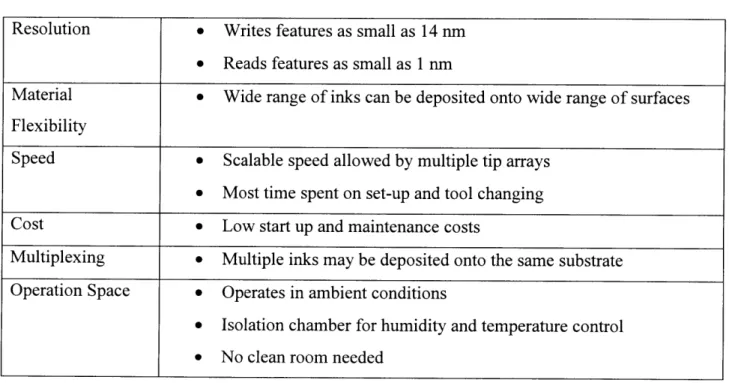
DPN can be used for drug printing, customized drug delivery, creating nanostructures relevant to current technology, as well as for a variety of experimental processes in surface patterning and parallel writing. DPN is a flexible process as far as nanofabrication goes and has many features that make it appealing for nanomanufacturing, including resolution, speed, material flexibility, and cost. The features and highlights of DPN are summarized in Table 2.1 below.
Table 2.1: DPN Features and Highlights Resolution * Writes features as small as 14 nm
0 Reads features as small as 1 nm
Material 0 Wide range of inks can be deposited onto wide range of surfaces Flexibility
Speed e Scalable speed allowed by multiple tip arrays
0 Most time spent on set-up and tool changing
Cost 0 Low start up and maintenance costs
Multiplexing * Multiple inks may be deposited onto the same substrate
Operation Space e Operates in ambient conditions
e Isolation chamber for humidity and temperature control
e No clean room needed
The above features of DPN make it an appealing alternative to standard lithographic techniques. A clean room is not necessary for operation because the risk of contamination that exists in photolithography and other lithographic techniques is avoided. DPN allows the creation of nanostructures in a single step, eliminating the need for resists and multiple time consuming processes. DPN can achieve very high resolution features, with linewidths as small as 14 nm and
same device is used to both read and write a pattern, so patterns of multiple inks can be formed or aligned on the same substrate.
The ability of DPN to achieve such high resolution depends of proper alignment of the tip. If the tip is not correctly aligned the written features will not be positioned accurately with respect to the substrate or accompanying features. Aligning the tip is currently a difficult and time consuming process; the majority of the time spent using the machine is spent on tip alignment in the initial setup of the machine and tip alignment during tool changes. The addition of an accurate and repeatable tool fixture will eliminate much of the setup time, therefore greatly improving the rate and reliability of the process.
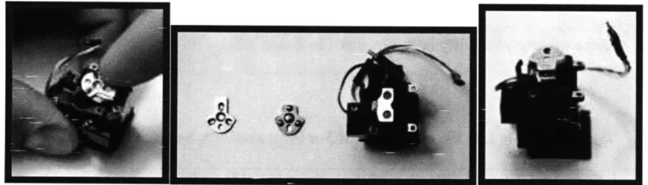
The current tip mounting process used by Nanolnk, a company that builds and sells DPN machines, for their machines is time consuming and involved. The goal of the kinematic fixture is to reduce the time and effort required to mount the tips in addition to improving the accuracy and repeatability of the tip position. Preparing the tip for proper alignment involves first mounting the tip into a probe holder that positions the tip in the correct orientation with the DPN machine and holds the tip in place while DPN operations are performed. If the tip is not properly mounted in the probe holder the success of the DPN operation is compromised. The probe holder
Figure 2.2: Probe holder used for positioning the tip onto the DPN machine
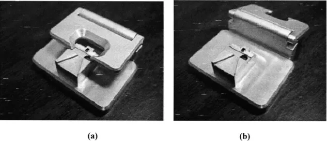
A mounting block is used to facilitate the process of mounting the tip in the holder. The mounting block includes a flat indent the probe holder fits into as well as an alignment area where the tip is aligned to the probe holder. The mounting block is shown with the cover in both the open and closed positions in Figure 2.3.
(a) (b)
Figure 2.3: Mounting block used for securing tip into probe holder in closed (a) and open (b) positions
The probe holder is first inserted into the mounting block and secured by pressing the cover closed. Then the tip is placed on the mounting block and lined up by eye to the center of the probe holder. The tip is sandwiched into the probe holder and held in place. Figure 2.4 shows
the tip being inserted into the probe holder.
Figure 2.4: Mounting of tip into probe holder
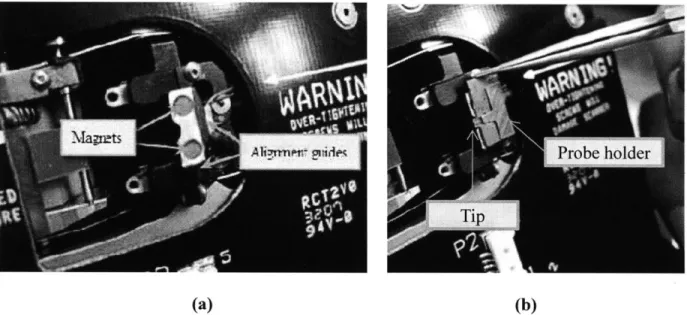
Once the tip is mounted in the probe holder, it must be installed onto the DPN machine. The probe holder attaches to the machine scanner head assembly via the two small magnets. The alignment is done by lining up the flat sides of the probe holder with the two flat alignment guides on the scanner head assembly universal mount. The universal mount is shown in Figure 2.5.
(a) (b)
Figure 2.5: Universal mount on DPN machine, used for alignment of tip assembly. Magnets and alignment guides are shown (a) as well as the tip assembly placement (b)
After mounting the tip into the probe holder and mounting the probe holder to the machine, the tip must be aligned with respect to the machine. Currently a laser is used to align the tip. The tip is moved around very slowly, three microns at a time until the tip is located by the laser. This process can take approximately 45 minutes of repetitively moving the tip. The objective of the accurate and repeatable kinematic fixture is to eliminate the probe holder and the process of laser alignment for each tip. The groove side of the fixture will be mounted directly to the machine, and the tip will be mounted directly to the ball side of the fixture, so the tip will be accurately and repeatably located by the fixture to the machine.
An accurate and repeatable kinematic fixture would allow for the tip to be placed in a matter of seconds with accuracy and precision, thus removing the need for the current arduous and time consuming alignment process.
2.2 Design Requirements
The design requirements are defined foremost by understanding the problem and the need for accurate and repeatable fixturing. The problem is that small-scale fabrication processes do not meet the requirements in rate, quality, cost, and flexibility in order to become manufacturing processes. Current fixturing technologies allow for high repeatability at low cost at the large scale, but have not yet met accuracy, repeatability, and cost requirements for small-scale processes..
Specific functional requirements and constraints of the fixtures designed in this thesis were defined by the customer for a specific application, DPN. These requirements include accuracy of the probe tip location, repeatability of the fixture centroid, incremental cost of the system per probe or tool, fixture load capacity, tool change out time, and fixture size or envelope. The functional requirements and constraints for the fixture for DPN applications are summarized in Table 2.2.
Table 2.2: Functional Requirements and Constraints
Probe tip placement accuracy 1000 nm
Fixture centroid repeatability 100 nm
System incremental cost per probe or tool 50 $
Fixture load capacity 1 N
Fixture change-out time 15 s
Calibration time 60 s
The functional requirements and constraints allow the fixturing technology to be easily adapted into standard DPN machines and other nanomanufacturing equipment. The accuracy and repeatability requirements ensure accurate and repeatable tool placement, thus greatly reducing tool change-out time and improving the overall rate of the process. It is important to achieve a balance of cost and performance with this fixture design; it is not necessary to design the most repeatable KC ever made, but it is necessary to have a low-cost fixture that meets the
performance requirements as well as the cost requirements. The fixture envelope is also
important, as customers are not likely to use a fixture on their machines if they must reconfigure the whole machine in order to allow space for the fixture. Most nanomanufacturing equipment does not have significant free space in which to add additional elements, so it is important to keep envelope in mind when designing a fixture.
2.3 Kinematic Fixtures: General Concept
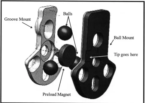
The fixtures in this thesis were designed to be accurate and repeatable. The repeatability is achieved via exact constraint design methods, and the accuracy is achieved via calibration. The fixture is a traditional three ball, three groove passive kinematic coupling. The fixture is shown in Figure 2.6. The groove side mounts to the desired equipment, and the tool is mounted to the ball side, thus repeatably and accurately attaching the tool to the machine.
Groove Mount
Figure 2.6: Accurate and repeatable kinematic fixture CAD model exploded view
The calibration is achieved by an adjustable interface on the ball side of the kinematic coupling. The ball side of the fixture includes three holes for the balls to be placed into. The three holes are 152.4 micrometers larger than the balls, allowing the position of each ball to be adjusted within the constraints of the hole. The ball side of the KC is shown in Figure 2.7.
Figure 2.7: Ball side of the KC, showing the clearance between the balls and the holes to allow for position adjustment
Ball Mount
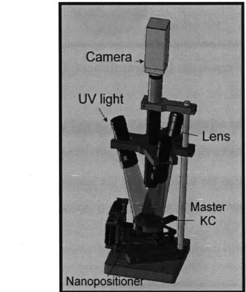
After the balls are set into the oversized holes, the holes are filled with a UV curing epoxy, which fills the gap between the ball and hole. This epoxy is in a liquid state until subjected to UV light, at which point it becomes solid. The kinematic coupling is set up on an assembly station that includes a microvision system that monitors the position of the coupling. The fixture assembly station, including the vision system, nanopositioner, and ultraviolet light set-up is shown in Figure 2.8.
Figure 2.8: Assembly station CAD model, including vision system, nanopositioner, UV lights, and master KC fixture
The vision system is used to measure the error in position of the kinematic coupling and informs a nanopositioner of that error. The nanopositioner is then instructed to correct for the error in alignment, at which point the vision system is used to verify the corrected position of the
coupling. Once the alignment is correct, the area is flooded with UV lights and the position of the balls is set in the UV cure epoxy. This allows accuracy while taking advantage of the passive KC's repeatability characteristics.
CHAPTER
3
REPEATABILITY
3.1 Definition and Importance of Repeatability
Repeatability is a measure of variation among repeated measurements. Though repeatability and accuracy are often thought to have the same meaning, they have very different meanings in the context of precision engineering. Measurements are accurate when they agree with the true value of the quantity being measured. They are repeatable when individual measurements of the same quantity agree. A measurement is accurate only if the measurement is correct. A
measurement is repeatable if the results are essentially the same each time a measurement is made. Measurements are therefore repeatable, but not necessarily accurate, when they are reproducible.
Figure 3.1 (4) below illustrates an analogy explaining repeatability and accuracy using targets. Accuracy is a measure of how close the arrow comes to the center of the target, and repeatability is a measure of how tightly the arrows are clustered together.
Accuracy
Repeatability
Accuracy & repeatability
Figure 3.1: Target analogy for repeatability and accuracy
Repeatability is especially important in small-scale manufacturing for tool changing and part locating. It is necessary to know the exact location of your tool and part. As the repeatability of the system improves, so does the likelihood that you know the location of the tool and part.
Repeatability of tool placement requires a repeatable coupling interface. Common coupling methods include elastic averaging, passive kinematic couplings, active kinematic couplings, compliant kinematic couplings, and quasi-kinematic couplings. These mechanisms are discussed in detail in Chapter 1. Typical alignment mechanisms are compared in Figure 3.2 (3) in terms of cost and achievable repeatability. Kinematic couplings are inherently highly repeatable due to their exact constraint design; the number of constraints is equal to the number of degrees of freedom constrained. However, repeatability within 500 nanometers is extremely difficult to achieve with a traditional passive kinematic coupling design due to friction, surface finish, stability of materials, and compliance errors. Friction between the contact surfaces is the most significant contributor to nonrepeatability, which can be minimized by improving surface finish at the coupling interface, adding flexures to the coupling interface, or by changing the groove angle. Improving repeatability is a common research interest in the field of fixture design,
specifically in kinematic couplings. In addition to reducing friction at the coupling interface, one of the most effective methods of improving repeatability is by increasing the preload force on the coupling. Preload will be discussed further in Chapter 3.2.
Repeatability 0.01 m0,10 s 1.0 pm 10 sm Elastic averaging Compliant kinematic Quasi-kinematic Active kinematic Passive kinematic
Figure 3.2: Cost and repeatability comparison for alignment mechanisms
With two major functional requirements being repeatability and cost, the fixture design was based on the passive kinematic coupling. The $50 incremental system cost per tool specified in the functional requirements discussed in the previous chapter is possible with a passive kinematic coupling design. The 100 nanometer repeatability requirement proves to be a more difficult problem. With a standard passive kinematic coupling design, it is customary to achieve repeatability of approximately 500 nm. The customer requirements of this fixture demanded an
3.2 Kinematic Coupling Design
The functional requirements of a kinematic coupling are as follows:
- it connects two parts or assemblies - can be separated and rejoined on demand . fine repeatability
- some level of accuracy - some level of stiffness - is cost appropriate
The intrinsic flaws of kinematic couplings are that they (i) can have high stress concentrations at the contact points, (ii) do not permit sealed joints, and (iii) usually offer moderate stiffness and load capacity.
The first design to consider is a three-ball, three-groove design, shown in Figure 3.3 (13). The advantages of the three-groove design are that it is symmetric and therefore more evenly distributes the contact forces and is also less expensive and easier to manufacture. This design allows for better centering and is not sensitive to thermal expansion, as it tends to expand about a center point. Its disadvantages are that the six point contacts create high stress concentrations and this design usually has low stiffness and load carrying capacity in comparison to other designs.
Figure 3.3: Three-groove kinematic coupling
The three-groove design may be compared with the Kelvin model: a tetrahedral socket, groove, and flat, as shown in Figure 3.4 (4). The tetrahedral socket of this model adds a natural pivot point for angular adjustment, but it still contains six contact points, therefore still incorporating the same high stress concentrations. For high cycle applications it is best to use hardened corrosion resistant materials (e.g., ceramics or hardened steel) for contact surfaces to prevent nonrepeatability due to high contact stresses. Countermeasures to the high stress concentrations and low stiffness and load capacity in both the three-groove and the tetrahedral-groove-flat designs include modifying the point contacts so they become line contacts (for example, turning the tetrahedral socket into a conical socket) or by increasing the area of contact by substituting gothic arches for the grooves or canoe-shaped balls for the traditional spheres.
Figure 3.4: Kelvin kinematic coupling
The symmetry inherent in a three-groove KC model aids in reducing manufacturing costs, and the use of grooves for all contact regions minimizes the overall stress state in the KC; therefore it is generally best to use a three-groove design for fixturing applications. Once the basic KC ball and groove layout is determined, the orientation of the grooves must be optimized. In order to guarantee stability in a 3-groove kinematic coupling, the normal vectors to the contact forces should bisect the angles between the balls. Additionally, the contact force vectors should intersect the plane of coupling action at a 45 degree angle to balance stiffness in all directions, therefore implying a 90 degree angle groove (18). A stable 3-groove kinematic coupling layout is shown in Figure 3.5 below. The angle bisectors intersect at a point that is also the center of the circle that can be inscribed in the coupling triangle; this point is referred to as the coupling centroid, and is only coincident with the coupling triangle's centroid when the coupling triangle is an equilateral triangle (19).
Figure 3.5: Ball and groove layout for optimal stability (18)
3.3 Error
Systematic errors influence the accuracy but not the repeatability. It is possible to get
measurements that are consistently the same but systematically wrong. Random errors influence both the accuracy and repeatability of the measurement. Systematic errors can be reduced by improving the accuracy of the tools and equipment used or by decreasing human error of the individual making the measurement. Random errors can be reduced by averaging the results of many measurements of the same quantity (20).
3.3.1 Friction
Friction plays an important role in determining the performance of a kinematic coupling. Friction between the coupling surfaces is the most influential source of repeatability error in a KC. When a KC is fully engaged, it settles into a position where potential energy is minimized; that is, the balls slide down into the grooves as far as is possible. Friction between the balls and grooves prevents the KC from settling into this minimum energy state. Even though the contacting surfaces may appear to be smooth, they may contain micrometer scale asperities, so for applications requiring nanometer scale repeatability the surfaces actually seem rough. Only the surface asperities really touch each other. Friction is due to the interaction between the asperities of the ball and groove surfaces. The ball catches on surface asperities on the groove surface and sits in an unstable position. The ball may likely slide off of a particular catching asperity and the coupling position will move. This is illustrated in Figure 3.6 (4).
Mate n
Mate
n +
1
Figure 3.6: The effect of surface asperities on couplingThe friction at the coupling interface depends on the surface finish of the balls and grooves. Therefore, achieving good surface finish is one of the most important parts of KC design. Ball and groove surface finish should be specified in the design and can be achieved by optimizing
machining feeds and speeds, polishing, or brinelling the surface. Brinelling is a permanent deformation in the surface of the material caused by contact stress that exceeds the material elastic limit. The result is a permanent shiny dent in the surface. Brinelling the surface destroys the asperities, thus smoothing the area of contact and reducing friction.
Friction can also be mitigated by lubrication at the contact interfaces using high pressure grease or by adding flexures to the KC (11) (5). Adding flexural hinges to the ball side of the KC has been shown to improve the repeatability by a factor of 10, from repeatability on the order of hundreds of nanometers to repeatability of approximately 30 nanometers. This concept is exemplified by the flexure-enabled KC shown in Figure 3.7 below. The KC designed by Schouten, et al with flexures added to the grooves is shown in Figure 3.8.
(a) (b)
Figure 3.7: KC modified with flexural hinges on the ball side to improve the repeatability by reducing friction. The entire KC is shown in (a), and a close up of the ball flexures are
Figure 3.8: Ball in KC vee-groove modified with elastic hinges
For low-cost, small-scale fixtures, such as those in this thesis, adding flexures may not be an option, thus friction at the coupling interface must be controlled via surface finish and lubrication. Polished and hardened surfaces of ceramics or stainless steel are good options. Surface finish can also be controlled in manufacturing by optimizing the cutting speed and feed rate. Optimal feeds and speeds for various materials can be calculated based on the material of the work being cut, the material of the cutting tool, the economical life of the tool, and other cutting conditions. Cutting speeds and feeds can also be looked up in reference books, charts, or tables (21) but are always subject to change depending on the cutting conditions. At the small scale, controlling the surface finish to the specified roughness is often difficult, so additional steps beyond manufacturing may need to be taken. Post-manufacturing options for surface finish include polishing or brinelling the contact surfaces to remove surface asperities, or lubricating the contact surfaces with wax or high pressure machine grease to fill in the asperities.
The coupling surface must also be thoroughly cleaned because debris is another source of additional friction. Double sided tape may be used to remove any obvious debris, and compressed air or an oil mist may be used to clean the ball and groove surfaces. Compressed air