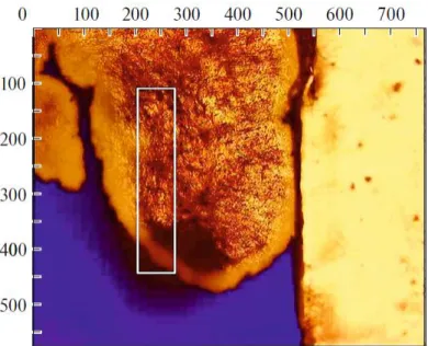
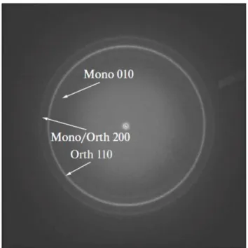
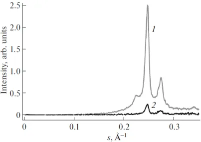
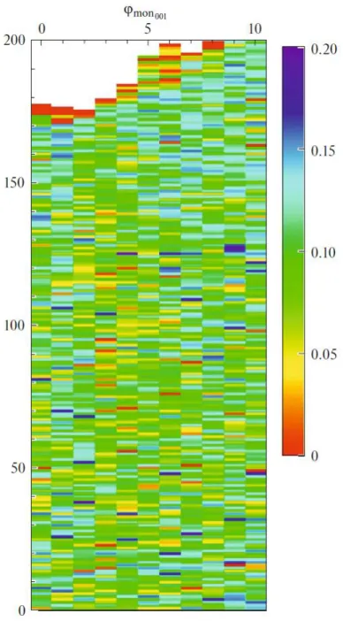
Pattern of Monoclinic Phase Distribution in Nascent UHMWPE Particles
Texte intégral
Figure
Documents relatifs
In the high-density phase diagram of hard ellipsoids of revolution we have found a crystal that is more stable than the stretched-fcc structure proposed by Frenkel and Mulder 关 2
Transport currents flow in a layer of thick- ness A near the surface ; out of this layer the vortex system remains uniform.. Let us consider the inhomogeneous mixed phase in
Preliminary X-ray study of the ordering phase transitions in the inclusion
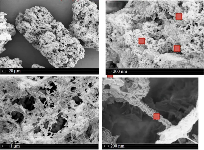
Ultra‐high‐molecular‐weight polyethylene (UHMWPE) has been treated by a helium/oxygen Dielectric Barrier Discharge as well as a rotative
A higher number of shorter than vdW distance close contacts was observed within the monoclinic phase as compared to that for the cubic phase, underlining the increased
If we now come back to the X-ray diffraction pattern, we may notice that the diffuse line (f) is slightly curved towards the meridian Oz. This may remind the
Structure of comb~shaped liquid crystalline polysiloxane with phenyl benzoate mesogeluc side group has been studied The analysis of the scattenng intensity and calculation of
Pour le doublet d 4 d’ 4 la régularité de la séquence de croisements observés rend plausibles deux hypothèses et deux seulement, qui sont reportées dans le
