Conceptual design study for heat exhaust
management in the ARC fusion pilot plant
The MIT Faculty has made this article openly available. Please share how this access benefits you. Your story matters.
Citation Kuang, A.Q., et al. "Conceptual design study for heat
exhaust management in the ARC fusion pilot plant." Fusion Engineering and Design 137 (Dec. 2018): p. 221-42 doi: 10.1016/ j.fusengdes.2018.09.007 ©2018 Author(s)
As Published 10.1016/J.FUSENGDES.2018.09.007
Publisher Elsevier BV
Version Author's final manuscript
Citable link https://hdl.handle.net/1721.1/124299
Terms of Use Creative Commons Attribution-NonCommercial-NoDerivs License
1
Conceptual design study for heat exhaust management
in the ARC fusion pilot plant
A.Q. Kuang1, N.M. Cao1, A.J. Creely1, C.A. Dennett2, J. Hecla2, B. LaBombard1, R.A. Tinguely1, E.A. Tolman1, H. Hoffman1, M. Major1, J. Ruiz Ruiz1,
D. Brunner1, P. Grover3, C. Laughman3, B.N. Sorbom1, D.G. Whyte1 1MIT Plasma Science and Fusion Center, Cambridge MA 02139 USA 2MIT Nuclear Science and Engineering Department, Cambridge MA 02139 USA
3Mitsubishi Electric Research Laboratories, Cambridge MA 02139 USA
© 2018. This manuscript version is made available under the
CC-BY-NC-ND 4.0 license
http://creativecommons.org/licenses/by-nc-nd/4.0/
2
Conceptual design study for heat exhaust management
in the ARC fusion pilot plant
A.Q. Kuang1, N.M. Cao1, A.J. Creely1, C.A. Dennett2, J. Hecla2, B. LaBombard1, R.A. Tinguely1, E.A. Tolman1, H. Hoffman1, M. Major1, J. Ruiz Ruiz1,
D. Brunner1, P. Grover3, C. Laughman3, B.N. Sorbom1, D.G. Whyte1 1MIT Plasma Science and Fusion Center, Cambridge MA 02139 USA 2MIT Nuclear Science and Engineering Department, Cambridge MA 02139 USA
3Mitsubishi Electric Research Laboratories, Cambridge MA 02139 USA
The ARC pilot plant conceptual design study has been extended beyond its initial scope [B. N. Sorbom et al., FED 100 (2015) 378] to explore options for managing ~525 MW of fusion power generated in a compact, high field (B0 = 9.2 T) tokamak that is
approximately the size of JET (R0 = 3.3 m). Taking advantage of ARC’s novel design –
demountable high temperature superconductor toroidal field (TF) magnets, poloidal magnetic field coils located inside the TF, and vacuum vessel (VV) immersed in molten salt FLiBe blanket – this follow-on study has identified innovative and potentially robust power exhaust management solutions. The superconducting poloidal field coil set has been reconfigured to produce double-null plasma equilibria with a long-leg X-point target divertor geometry. This design choice is motivated by recent modeling which indicates that such configurations enhance power handling and may attain a passively-stable detachment front that stays in the divertor leg over a wide power exhaust window. A modified VV accommodates the divertor legs while retaining the original core plasma volume and TF magnet size. The molten salt FLiBe blanket adequately shields all superconductors, functions as an efficient tritium breeder, and, with augmented forced flow loops, serves as an effective single-phase, low-pressure coolant for the divertor, VV, and breeding blanket. Advanced neutron transport calculations (MCNP) indicate a tritium breeding ratio of ~1.08. The neutron damage rate (DPA/year) of the remote divertor targets is ~3-30 times lower than that of the first wall. The entire VV (including divertor and first wall) can tolerate high damage rates since the demountable TF magnets allow the VV to be replaced every 1-2 years as a single unit, employing a vertical maintenance scheme. A tungsten swirl tube FLiBe coolant channel design, similar in geometry to that used by ITER, is considered for the divertor heat removal and shown capable of exhausting divertor heat flux levels of up to 12 MW/m2. Several novel, neutron tolerant diagnostics are explored for sensing power exhaust and for providing feedback control of divertor conditions over long time scales. These include measurement of Cherenkov radiation emitted in FLiBe to infer DT fusion reaction rate, measurement of divertor detachment front locations in the divertor legs with microwave interferometry, and monitoring “hotspots” on the divertor chamber walls via IR imaging through the FLiBe blanket.
3
Contents
1. Introduction ... 4
2. Assessment of the divertor heat flux challenge for ARC compared to lower field reactor designs ... 7
3. Magnetic equilibrium with X-point target divertor ... 9
3.1 Design goals ... 9
3.2 Magnetic equilibrium ... 11
3.3 Internal trim coils ... 14
3.4 Magnetic sensors ... 17
3.5 Forces on poloidal field coil set ... 19
4. Neutronics ... 20
4.1 Divertor and vacuum vessel design ... 21
4.2 Neutron shielding ... 23
4.3 Tritium breeding ratio ... 24
4.4 Power deposition ... 25
5. Heat exhaust management system ... 26
5.1 System level design... 27
5.2 Divertor target design ... 29
5.3 Divertor thermal analysis ... 33
5.4 Divertor thermomechanical analysis... 34
5.5 System level analysis ... 37
6. Divertor detachment control and novel diagnostics enabled by the unique design features of ARC ... 38
6.1 The need for passively stable detached divertors ... 38
6.2 Monitoring divertor detachment location with microwaves ... 41
6.3 Infrared imaging of divertor ‘hot spots’ through the FLiBe blanket ... 42
6.4 Cherenkov radiation in FLiBe as a measure of fusion reaction rate ... 43
7. Future Research Needs ... 44
8. Summary ... 47
4
1. Introduction
A recent study [1] provided a conceptual design for a compact fusion pilot plant and fusion nuclear science facility based on the exploitation of newly-available high-temperature superconductor (HTS) tapes for high-field magnets. The ARC (Affordable Robust Compact) design has several attractive features including:
1. plasma energy gain Q > 10 at compact size (major radius, R ~ 3.3 m) due to high magnetic fields (peak B on coil ~ 23 T, magnetic field on the plasma axis, B0 ~ 9.2 T) enabled by the use of REBCO (rare-earth barium copper
oxide) HTS,
2. demountable toroidal field coils for vertical, modular replacement of interior components – a feature permitted by the improved material thermal and cooling properties at the higher operating temperature range (~20-30 K) enabled by REBCO,
3. a thin, replaceable, actively-cooled modular vacuum vessel (VV) with a conformal, close fit to the plasma poloidal shape, and
4. a liquid immersion blanket of FLiBe molten salt – which completely surrounds the VV; this high-temperature, single-phase, low-pressure fluid serves as (1) an effective medium for neutron moderation, heat removal, shielding and capture for efficient tritium breeding and (2) a large thermal reservoir to be directed to cool first-wall and VV components.
A key design challenge not addressed in the original ARC study was plasma power exhaust. This concern naturally arises due to the high global power density; as in the ITER design [2], ~500 MW of fusion power are produced, but in ~1/8th the volume of
ITER. This high global power density is an attractive feature for a pilot fusion device – and likely necessary for extrapolating to commercial fusion power devices. However, a concern is that ARC may not have the ability to adequately exhaust ~150 MW of fusion alpha heating plus external radio-frequency (RF) heat deposited into its compact core. As discussed in more detail below, this concern is not unique to ARC; it is generic to all fusion reactor designs that must attain a certain neutron flux density (e.g., Fusion Nuclear Science Facility, FNSF) or maximize core fusion power density for economic considerations. In this regard, ARC’s high magnetic field enables neutron wall loading that is similar to these large reactor designs but with smaller volume and reduced total power [3]. The net effect is that heat flux densities entering into ARC’s divertor are projected to be no worse than the larger reactor designs. In any case, new robust power exhaust management solutions are needed.
The original ARC conceptual design study did not include an assessment of potential divertor solutions. However, some specialized features of the boundary/divertor plasma were examined [1]. The use of high-field side radio frequency (HFS-RF) launchers was explored, which had been shown previously to be attractive for efficient current drive and current profile control [4]. Recent studies of HFS-RF have further highlighted potential advantages: decreased launcher neutron damage and improved tritium breeding [5], efficient lower-hybrid current drive and ICRF heating/current drive due to improved accessibility [6], and enhanced impurity screening of HFS impurity sources [7,8]. The original ARC design study also performed neutron transport calculations to assess
5
neutron shielding and tritium breeding [1]. The potential impact of a tungsten divertor target on neutronics and tritium breeding was assessed by attaching tungsten panels to the plasma-facing side of the VV where the lower divertor would be located; yet this was not meant to be a realistic divertor target plate geometry. Finally, the ability to actively cool a double-walled VV with FLiBe was assessed with thermal hydraulic calculations and simulations. This coolant channel design was found capable of handling both volumetric heating of the VV from neutrons and surface heating of the VV wall from core plasma photon radiation.
With regard to developing a plasma power exhaust management system, the original design study clearly identified ARC’s unique design advantages:
1. the attractiveness of FLiBe as a coolant due to its very large temperature window in the liquid state, ~700-1700 K, and volumetric heat capacity, which allows for single-phase, low-pressure heat transfer,
2. the geometric simplification and advantage of having an extremely large fluid heat sink, i.e. the liquid blanket, immediately adjacent to the solid components, the VV and plasma-facing components (PFCs), which require active cooling, and 3. the low electrical conductivity of FLiBe, and its moderate viscosity, which greatly
reduce magneto hydrodynamics (MHD) effects in fluid flow and enable sufficient fluid flow rates at modest pressure drop and pumping power.
The goal of this follow-on study is to explore and exploit these features for heat exhaust management with a conceptual design that includes an advanced divertor, while also retaining the essential features of the original ARC design: overall plasma geometry (major radius, minor radius, elongation), double-null divertor magnetic topology, demountable toroidal field (TF) coils, FLiBe liquid immersion blanket, and 525 MW DT fusion power. It is important to note that the goal of this study is not to develop a complete, self-consistent design for a power management system but to explore novel approaches made possible by ARC’s unique design and to assess them from basic engineering considerations. It is also important to note that this study only explores potential options for steady state power management; start-up and shut down phases of the reactor and the impact of disruptions are not considered, for example.
Research performed over the past several years has clearly identified the challenges facing steady state heat exhaust management for tokamak power reactors, and they are daunting – in particular the requirement of maintaining a dissipative, cold divertor plasma in the presence of a narrow heat flux channel that is projected to be less than 1 mm wide for the poloidal magnetic fields of a power reactor [9,10]. At the same time, promising results have come from theoretical [11-13] and experimental [14-16] explorations of advanced divertor geometries, which indicate that such configurations may be able to meet this challenge. Advanced divertor geometries generally feature extended volumes for the divertor, additional poloidal field nulls, and shaping control beyond what is used for a standard vertical target divertor, as employed by ITER. However, Lackner and Zohm [17] have cautioned that currents in the poloidal field (PF) coils needed to create some of these configurations could be a major technological challenge – if the PF coils are placed far from the plasma to accommodate neutron shielding and/or outside the TF coils due to assembly constraints. TF coils produced with low-temperature superconductors (e.g. Nb3-Sn) cannot be segmented and therefore, as a practical
6
consideration, such superconducting PF coils must be placed outside the TF. Because ARC has demountable TF coils, superconducting PF coils can be placed inside the TF, much closer to the plasma allowing for much lower total coil currents and forces.
The placement of PF coils inside the TF is an approach taken by many tokamaks, such as DIII-D [18], Alcator C-Mod [19] and TCV [20]; these physics experiments utilize this feature to enhanced plasma shaping capabilities. A principal difference is that ARC also has a 1-meter-thick FLiBe blanket surrounding its plasma core for neutron shielding. We find that a long-legged, advanced divertor can be implemented in ARC simply by carving out an appropriate space in the FLiBe blanket. Thus, the implementation of an advanced, long-legged divertor in a power-producing DT fusion reactor does not necessarily require a decrease in core plasma volume and/or increase in TF magnet size.
The present study explores the implementation of a X-point Target (XPT) divertor in ARC, similar to the XPT configuration proposed for the ADX divertor test tokamak [13]. In this configuration, an additional (secondary) poloidal magnetic field null is formed at the end of an extended outer divertor leg in both the lower and upper divertors. Recent modeling by Umansky et al. [21] has shown that this configuration may attain a stable, highly dissipative (i.e., fully detached) divertor, accommodating upstream power densities that are ~10 times higher than for standard vertical target divertors. Plasma fluid modeling is presently underway for the divertor configuration specifically chosen in this follow-on ARC study and will be published in a separate paper [22]. Initial results indicate that a stable, fully detached divertor plasma state may be achieved even at the maximum levels of divertor power exhaust anticipated (~105 MW) while only requiring minimal levels of impurity seeding (e.g., ~0.5% neon, fixed fraction). While the present design study focused on implementing an XPT for ARC, this design exercise clearly indicates that other advanced divertor ideas that utilize a long legged geometry (e.g. super-X divertor [23]) may be implemented as well.
The organization of this paper is as follows. Section 2 reviews power exhaust requirements for ARC relative to other reactor designs, taking into consideration the empirically observed poloidal magnetic field scaling of scrape off layer power widths and the economic needs of attaining a certain neutron power loading and/or core fusion power density. Contrary to initial expectations, scaling considerations reveal that heat flux densities entering into the divertor of ARC will be no worse than those anticipated for other reactor designs such as ARIES [24], ACT1 and ACT2 [25], and European DEMO [26], which in general are much larger devices operating at moderate magnetic fields. Section 3 examines requirements for the placement of PF coils to achieve the XPT divertor configuration for an ARC magnetic equilibrium. Superconducting poloidal field coil locations are specified with consideration of neutron shielding, current densities in the HTS, forces on the coils and the attainment of the XPT divertor magnetic geometry. The resultant modification to the VV shape impacts other aspects of heat exhaust management, such as requirements for plasma position and shaping control, and consideration of neutron damage to high heat flux divertor target components.
Neutron transport in the modified VV and blanket configuration is addressed in Section 4, with a focus on obtaining the required shielding for the inner PF coils and maintaining the tritium breeding ratio (TBR). This study also examines the neutron flux at primary
7
divertor surfaces – in particular its softened energy spectrum – which is a benefit of geometrically separating and shielding these surfaces from line-of-sight view to the core plasma neutron source.
Taking advantage of the favorable features of FLiBe listed above, combined with new ideas for cooling channel geometries afforded by advanced manufacturing, Section 5 explores novel design approaches for an integrated heat exhaust management system. Schemes to implement forced flow cooling of vacuum vessel and divertor components are developed, capable of handling ARC’s full thermal output while minimizing pumping power. The divertor cooling system borrows embedded swirl tubes from the ITER design [27], but with FLiBe coolant. The design is shown capable of removing surface heat fluxes of up to 12 MW/m2. Although the designs presented here are only conceptual, they show that the required levels of local and global heat transfer can be obtained in ARC with acceptable coolant pumping power (< 1% of fusion power) – a necessary requirement for an economical fusion power plant.
Finally, Section 6 explores the issues of plasma detachment control and diagnostics that are enabled by unique aspects of the ARC reactor design. One of the key advantages of the XPT divertor, the large detachment power window [21], is explored with respect to steady state reactor operation. In addition, the long leg divertor geometry lends itself to a feedback control system of the detachment front location using microwave interferometry as a detector. Lastly, the optical transparency of the FLiBe blanket makes possible diagnostics that ‘look through’ the blanket: (1) thermal imaging of the external surface of the VV, (2) monitoring of the Cherenkov radiation produced in FLiBe to deduce the fusion reaction rate.
As in any conceptual design study, the overall goal is to identify not only what might be possible but also what needs further study. Key areas needing further investigation include: quantifying the power handling performance of the X-point target divertor; assessing and developing advanced manufacturing techniques, such as additive manufacturing, to construct the designs considered; employing advanced computational fluid dynamics for refined heat transfer analysis; quantifying the effects of neutron damage to HTS superconductors; and fully characterizing the optical properties of FLiBe, particularly in the radiation environment of a DT fusion reactor. These are discussed in Section 7.
2. Assessment of the divertor heat flux challenge for ARC
compared to lower field reactor designs
A critical challenge for any fusion power plant design is to implement a robust divertor system that can handle extreme power densities and also suppress damage to target surfaces that would otherwise arise from energetic particle sputtering and helium implantation. Lacking exotic solutions, such as liquid metal and/or vapor targets, this calls for the attainment of a stable, completely detached divertor plasma state. Based on the current understanding of plasma transport in the scrape-off layer (SOL), key parameters that determine the plasma temperature and density in the divertor – and thus the access window for detachment – are the midplane plasma pressure and peak parallel
8
heat flux. The plasma pressure at the midplane is more or less fixed by core confinement requirements for optimal fusion operation and is ubiquitous for all reactor fusion plasmas. The peak parallel heat flux is determined by cross-field energy transport mechanisms in the SOL, which are not yet quantifiable from first principles models. Recent measurements from multiple experiments provide some guidance. They have led to the ‘Eich scaling’ empirical relationship [9], which indicates that the upstream midplane power exhaust width scales inversely with poloidal magnetic field strength and is insensitive to reactor size. Based on these observations, one might conclude that a high-field compact reactor like ARC, (operating with a 1.5 T poloidal magnetic high-field with a ~0.4 mm boundary heat flux width) must operate at higher parallel heat fluxes in comparison to low-field large reactor designs such as ARIES [24], ACT1 and ACT2 [25], and European DEMO designs [26], which are already projected to have unmitigated parallel heat flux power densities entering their divertors exceeding 40 GW/m2. This raises a key question for the ARC design: Would the attainment of a fully detached state be inherently more difficult? In this regard, one must also consider the total power that must be exhausted into the SOL in these designs.
ARC features relatively high volumetric power density ~3.7 MW/m3 from 525 MW of fusion power produced in a 137 m3 plasma volume. This is accomplished below the no-wall beta limit and at high safety factor (q95~7) by taking advantage of higher field with
the REBCO superconductors and fusion power density scaling as ~B4. Yet, in comparison to the reactor designs listed above, ARC has a ~2-3 times higher surface area to volume ratio due its small size (R), which keeps its global areal power density at ~2.5 MW/m2, similar to the larger reactors. This situation is attractive from an economic point of view since materials cost is approximately proportional to volume, which means ARC is a lower entry point cost for a pilot plant since it is ~5-20 times smaller in volume than the other designs.
Based on the Eich scaling [9], the parallel heat flux entering into a divertor is proportional to PB/R [28] where P is the total heating power (~Pfusion/5 at high gain), B is
the toroidal magnetic field, and R is the major radius. At first glance this scaling appears highly unfavorable for high B, small R devices. However, one must also consider that P itself is constrained based on the device’s mission. In a FNSF, P/S ~ P/R2, is fixed by design in order to provide sufficient neutron flux density to test components. In a power plant P/V ~ P/R3, is fixed in order to meet power/cost economic targets. Thus, at high fusion power gain, the parallel heat flux in these devices scales as either q// ~ BR (FNSF)
or q// ~BR2 (power plant). The Eich scaling is therefore not necessarily punitive for heat
exhaust in small R, high B designs, when the global power density requirements are otherwise held fixed.
This somewhat counter-intuitive scaling, i.e. that small high field devices will improve the heat exhaust situation, essentially stems from the lack of any explicit size dependence in the Eich scaling. A more detailed study by Reinke [29] shows that access to a dissipative divertor is enabled by high B, in part due to the access to higher core densities due to the empirical density limit, nGreenwald ~ I/R2 at fixed aspect ratio, which disallows
9
turns out the q// ~ BR scaling is approximately followed because the total fusion power P
is smaller than the large reactors listed above yet the parallel heat flux is similar (12 to 40 GW/m2). So, to a first approximation, power exhaust in ARC is neither more nor less difficult than in much larger devices with lower field; yet the motivation to increase B and decrease R is clear from a costing view. We therefore treat the power exhaust challenge in ARC as being generically similar to other reactor designs and, in any case, seek to implement the most robust divertor system available.
3. Magnetic equilibrium with X-point target divertor
Recognizing the need to employ a very robust, high power density handling divertor solution for ARC, a long-leg XPT divertor configuration, combined with operation in balanced double null magnetic equilibria, was deemed highly desirable [28]. Recent analyses found this configuration to be extremely promising [21], attaining a factor of ~10 increase in power density compared to conventional divertors operating at the same upstream plasma conditions. In addition, the modeling shows that a stable, fully detached divertor state may be maintained over a large power window while avoiding the formation of ‘X-point MARFEs’ [30], which degrades core plasma performance. For conventional reactor designs, it is difficult to implement the PF coil set needed for such advanced magnetic divertor topologies. When PF coils are located outside TF coils, very large coil currents may be required [17]. Located inside the TF coils, the PF coils can become difficult to shield from neutron heating and damage. However, the situation is very different in ARC. Its demountable TF magnet combined with its highly conformal, immersion FLiBe neutron blanket might allow the implementation of advanced divertor solutions.
3.1 Design goals
This design effort sought to attain the following goals for the magnetic equilibrium, divertor geometry and PF coil set:
1. Identify a PF coil set that will reproduce the core plasma magnetic equilibrium and shaping of the original ARC specifications (current, elongation, triangularity, major radius) while producing an XPT divertor configuration in a double-null geometry.
2. Achieve this within the envelope of the TF magnet, consistent with the original ARC specifications, i.e., do not increase the size of the TF magnets.
3. Locate superconducting PF coils outside the FLiBe tank, with adequate shielding for neutrons (i.e., approx. ~1 meter of shielding line-of-sight to core) but inside the HTS TF magnet envelop, taking advantage of its demountability.
4. Use high temperature superconductors for PF coils with appropriate cross-sections so as to attain acceptable limits of current density, considering the magnetic fields at the coils and published data on REBCO high temperature super conductor performance [31].
5. Fully utilize ARC’s demountable TF coils, maintaining the ability to lift the integral vacuum vessel, divertor and cooling system assembly from the FLiBe
10
shielding tank as a single unit for maintenance and replacement, without disturbing the superconducting PF coil set.
6. Locate magnetic sensors in regions with adequate shielding against neutrons yet with sufficient time response and sensitivity to changes in magnetic equilibrium. 7. If non-superconducting coils are needed inside the neutron shield, identify
potential approaches that can meet the requirements of thermal loading and power dissipation.
8. Examine the overall forces on the PF coil set and identify a means to accommodate them.
In addition, the design sought to investigate and to potentially exploit the low electrical conductivity properties of the FLiBe blanket in order to:
1. potentially provide low-voltage electrical isolation for non-superconducting trim coils located within the FLiBe tank, and
2. potentially allow magnetic flux to penetrate through the blanket on short time scales. This could reduce the time response for poloidal flux sensors located on the outside of the shielding tank (making placement at this location an option) as well as reduce the penetration time and eddy current losses from fast poloidal flux swings from vertical stability control coils and divertor trim coils.
The output of this exercise is summarized in Figure 1. As described in detail in sections 3.2-3.5 below, we identified a magnetic equilibrium, divertor geometry, PF coil placement, and FLiBe tank geometry that could satisfy all of the design goals.
11
Figure 1: Magnetic equilibrium, poloidal field (PF) and trim (TR) coil set, vacuum vessel and FLiBe tank geometry identified by the ARC-Divertor design study. The green poloidal flux contour lines are spaced 1mm apart at the outer midplane. The design accommodates a long-leg, XPT divertor in a balanced double null configuration with elongation and triangularity maintained very close to the original ARC design while fitting within the original toroidal field (TF) coil envelope. (For viewing clarity, the radial build [1] and TF joints are highly simplified).
3.2 Magnetic equilibrium
Coil placements and magnetic equilibria were explored with the ACCOME MHD equilibrium code [32,33], using a customized GUI written in IDL to facilitate rapid scoping studies. This design was iterated in order to simultaneously meet all of the above requirements. First, a magnetic equilibrium was created that met the targeted requirements (balanced double null, divertor X-points, elongation, triangularity). The field at the coil locations was then calculated to determine the critical current density in the coils (discussed in Section 3.3) and thus the minimum coil size. This was then checked against the geometry of the FLiBe tank to ensure that the coils did not inhibit vertical removal of the vacuum vessel assembly. These results were then exported to perform a MCNP neutron transport calculation (discussed in Section 4) to ensure that the coils were sufficiently shielded to maintain a reasonable lifespan. The neutronics results were then used to guide the placement of the coils in the next iteration.
The final coil placement in this conceptual design is shown in Figure 1. It should be noted that this is a single point design; magnetic equilibria and PF coil currents for different values of central solenoid flux where not explored. Instead, the central solenoid
12
geometry and flux were taken from the original ARC design. However, since ARC is envisioned to attain a fully non-inductive steady state condition (i.e. fixed central solenoid flux and PF currents), we consider this magnetic equilibrium as being appropriately representative for the design study. As specified in the original ARC paper, the design includes a plasma current of 8.0 MA, major radius of 3.3 m, elongation of 1.8, and triangularity of 0.375 [1]. The divertor coils create XPT divertors in the upper and lower divertor legs. The primary X-points are located at a major radius of 2.9 m while the secondary, divertor X-points are located at a major radius of 3.7 m. This provides a factor of 1.3 in total flux expansion (i.e. parallel flux bundle areal expansion) between primary and divertor X-points. In combination with neutral compression effects and plasma recycling on the divertor side walls [21], total flux expansion helps to stabilize thermal detachment fronts [34]. UEDGE simulations performed for an XPT divertor [21] based on the ADX device [28] find that this geometry can provide a wide operational power window for stable power exhaust, which is critical for heat flux management and control (discussed further in section 6).
The minimum plasma-wall gap was designed to be approximately 20 times the heat flux width (8 mm, mapped to the outer midplane). The present design takes advantage of significant poloidal flux expansion and a tilted plate geometry to reduce anticipated heat loads on the inner divertor target. Recent experiments in Alcator C-Mod found that approximately 10% of the power into the scrape-off layer goes to the inner divertor target plates in balanced double-null discharges (L, H, and I-mode) [35]. Thus, the simple inner divertor target geometry may be appropriate. Further optimization of first-wall surfaces should be explored, such as providing for tilting of inner and outer divertor target plates at strike point locations and more careful shaping at the entrance of the outer divertor chamber, but this exceeds the scope of the present study.
The magnetic equilibrium and divertor topology is achieved with divertor PF coil currents of 3.9, -4.4 and 5.2 MA, as indicated in Figure 2. These currents are achievable with new high performance superconductors. As shown in Table 1, all of these currents are well within the critical current density of REBCO HTS as they are sized in Figure 2 (to scale), even accounting for the high background magnetic field strengths. The PF coils are located just outside the FLiBe tank, and would require thermal insulation as described in [1]. The REBCO HTS critical current densities were calculated from the specifications found in [31]. As a baseline, the low end of the ‘premium tape’ was used (Je =275 A/mm2 at 77 K and 0 T). Accounting for the different magnetic fields and
temperature was done using the ‘lift factors’ included in the reference. ‘Lift factor’ is a magnetic field dependent parameter that quantifies the change in Je resulting from
operation at temperatures lower than 77 K and fields greater than 0 T. For example at 20 K and 17 T a ‘lift factor’ of 1.27 was estimated resulting in Je =350 A/mm2. This is a
conservative estimate, since the tape performance has improved considerably since the publication of these specifications. Furthermore, the calculations utilize the total magnetic field strength at the coil location, from both toroidal and poloidal fields, applied along the most detrimental direction to tape performance (perpendicular to the tape direction). This again provides a conservative estimate of the coil critical current, as the actual angle of the field will slightly increase the available critical current density. In
13
addition, these calculations assume an operating temperature of 20 K, as is the case with the toroidal field magnets [1]. Finally, the calculations assume that the coil will be 20% superconductor and 80% structure, which are conservative considering the relatively low hoop stresses applied to these coils, discussed further in Section 3.5. The coils have been sized such that they are large enough to stay below 65% of the critical current density (calculated using the assumptions stated), while still allowing vertical removal of the VV, greatly simplifying maintenance.
Figure 2: Current and spacing requirements of HTS divertor coils, allowing vertical removal of the vacuum vessel. All coils operate at less than 6 MA, and are well within the critical current density of REBCO HTS. Internal copper trim (TR) coil locations and currents needed to vertical stability and divertor x-point control. Trim coil currents are below 20 kA, minimizing power consumption. Their close proximity to the plasma allows fast corrections to the magnetic geometry.
In addition to equilibrium coils, the ARC divertor conceptual design also includes trim coils, which must respond to and correct for changes in the magnetic geometry on relatively fast time scales. The divertor X-point geometry presented here is sensitive to approximately ± 2% changes in the total plasma current, as well as approximately 5 cm vertical and radial displacements to the core plasma. Each of these events would cause the flux surface passing through the divertor X-point to change by 1 mm mapped to the outer midplane. The magnetic geometry must therefore be corrected on fast time scales in order to prevent an uneven distribution of heat loading to the divertor resulting in damage. Placing the trim coils inside of the FLiBe tank (Figure 2) reduces the current requirements of the coil and minimizes the amount of conducting material between the coils and the plasma, thus reducing the field propagation time to ~50 ms, as discussed in section 3.4. However, this placement also means that the coils must be designed to survive the high temperature and large neutron flux inside of the FLiBe tank. The trim coils require a maximum ~20 kA to correct the magnetic perturbations discussed above, so instantaneous power consumption is minimized (~25 kW per coil), although time-averaged power consumption is assumed to be negligible since these coils are activated temporarily to address equilibria shifts. Note that due to the narrow heat flux width, a vertical displacement in the plasma on the order of a millimeter can result in a loss of balanced double null and a significant increase in heat-flux to the dominant outer divertor or, even worse, to an inner divertor surface. Such displacements are a challenge to detect
14
and correct reliably with magnetic sensors. Section 6 discusses the possibility of measuring the power sharing of the upper and lower divertors directly by sensing the detachment front positions in the outer divertor legs. This in turn can be used as a means to feedback control the plasma position and magnetic flux balance, using the parameters that matter most – divertor power loading.
All coil locations, sizes and currents are summarized in Table 1.
Table 1: Poloidal field coil design specifications
Divertor coils Vertical field
coils Trim coils PF1 PF2 PF3 PF4 PF5 TR1 TR2 TR3 Conductor REBCO Cu Current (MA) 3.9 5.2 -4.4 -1.4 -3.5 +/- 0.02 +/- 0.02 +/- 0.02 R (m) 1.80 4.85 4.85 6.13 6.57 4.20 3.59 3.98 Z (m) 3.03 2.70 2.10 2.78 1.70 2.85 1.97 1.70 Width (m) (radius (m) for trim coils) 0.20 0.20 0.20 0.20 0.20 0.11 0.11 0.11 Height (m) 0.45 0.45 0.45 0.20 0.20 NA NA NA Br (T) 0.77 1.96 1.30 0.83 -0.01 NA NA NA Bz (T) 0.12 -0.49 -1.26 -0.71 -0.10 NA NA NA Btoroidal (T) 17.0 6.29 6.29 4.98 4.64 7.27 8.50 7.67 Current density (A/mm2) 43.3 57.8 48.9 35.0 87.5 0.5 0.5 0.5 Critical coil current density, 20% REBCO tape [31] (A/mm2) 70.0 95.4 95.8 114.4 122.4 NA NA NA Resistive power loss at full current (kW) NA NA NA NA NA 20 20 20
3.3 Internal trim coils
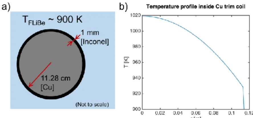
Low-current trim coils are employed in the ARC design to respond to and correct for plasma shape changes on fast time scales for vertical stability and divertor X-point control (Figure 2). The location of these coils inside the FLiBe tank, which operates at ~900 K, and close to the plasma in a region of high neutron fluence, precludes the use of superconductors. For this reason, we have considered a copper conductor design. These coils are considered replaceable along with the VV. We seek to determine if a design window exists for a copper coil that can withstand the high corrosion and the high temperatures of FLiBe in this environment – exacerbated by high electrical resistivity leading to ohmic losses, and neutron induced volumetric heating. For this purpose, we consider a heat transport analysis using a highly simplified copper conductor clad in
15
Inconel, to determine whether the copper will melt. We consider a solid copper cylinder with radius 11.28 cm, and a 1 mm Inconel 718 sheath. This may be viewed as a ‘single turn’ coil though we acknowledge that in reality a ‘multi turn’ coil will be needed. Our primary focus here is on assessing the feasibility of copper trim coils to stabilize the plasma as well as survive the high temperature environment.
Figure 3: (a) Cross section of a single-turn copper trim coil used in the present study. This design takes advantage of the electrically insulating properties of the FLiBe blanket, requiring no insulating layer between Inconel and FLiBe. (b) Temperature profile inside the trim coil. Note that the sharp rise at the edge of the coil is due to the poor thermal conductivity of Inconel in comparison to copper.
Magnetic equilibrium calculations carried out with the modeling software ACCOME [32,33] show that a total current of 20 kA in one single internal coil is able to correct for a 2% change in poloidal flux at the plasma boundary. Therefore, this was taken as the level of current needed for rapid correction to unexpected changes in magnetic equilibrium. Due to the proximity to the plasma, magnetic diffusivity timescales for the trim coils to affect the plasma equilibrium are estimated to be 50 ms (Section 3.4).
Analytical analysis was performed to estimate the ohmic heating and peak steady-state temperatures in these coils that results from running them for an extended period at 20 kA. The calculations were performed assuming the coil is immersed in a bath of 900 K FLiBe with material properties shown in Table 2. Table 3 shows the results of these calculations for one of the vertical stability copper coils. The resulting temperature profile is shown in Figure 3. The maximum on-axis temperature of the coil was found to be 1020 K. The total ohmic heat dissipation in each coil is ~20 kW assuming a worst-case scenario of 10 MW of nuclear heating at the location of the vertical stability coils (see Section 4). This low value of ohmic dissipation is negligible in power balance. Volumetric nuclear heating is the primary cause of the temperature rise inside the coils. When ARC is running, these coils would not operate with DC current, but rather with short pulses for plasma shaping control. However, even for DC operation, the peak on-axis coil temperature appears acceptable.
16
Table 2: Thermal and electrical properties of copper, Inconel and FLiBe used for DC heating and analysis and as inputs for COMSOL simulations of magnetic sensing time.
Thermal conductivity (W/m/K) Electrical resistivity (Ohm-m) Melting temperature (K) Copper 352 [36] 6.9×10⁻⁸ [36] 1,356 [36] Inconel 22.49 [37] 1.3225×10⁻⁶ [37] >1,500 [37] FLiBe 1 [38] 6.5×10⁻³ [39] 732 [38]
Radial and vertical forces acting on the trim coils were estimated by calculating the induced Lorentz forces at 20 kA coil currents in the background magnetic field at the coil locations. These were found to be small (Table 3), and the principal tensile stress in each coil is negligible when compared to the yield stress of Inconel 718 at 900 K.
Table 3: Operational parameters for single-turn copper trim coils.
Steady state parameters of each in-vessel coil Value
Cross section 0.04 m2
Total current 20 kA
Ohmic heating (Cu part) 18 kW Ohmic heating (Inconel 718 sheath) 0.02 kW
Nuclear heating ~10 MW (MCNP calculations) FLiBe temperature (at contact with Inconel sheath) 900 K
Peak temperature on coil ~1,020 K Principal stress σθ -2.9 MPa
Yield stress of Inconel 718 @ 900 K ~ 800 MPa [37] Radial force (Lorentz forces at 20 kA coil current) -0.02 MN/m Vertical force (Lorentz forces at 20 kA coil current) 0.3 MN/m
Due to their placement near the vacuum vessel, the vertical stability coils will be subjected to large neutron fluence. However, significant thermal and electrical degradation of the primary copper conductor due to radiation damage is not expected because the operational temperature of the coil is T/Tmelt ~ 0.75. At these high
temperatures, most radiation-induced defects will anneal quickly, leading to little long-term damage accumulation [40]. Radiation-induced degradation coupled with FLiBe corrosion of the Inconel sheath will likely be a life-limiting factor for these coils, as more damage will likely be retained at the lower homologous temperature for Inconel (T/Tmelt ~
0.62). A quantitative estimate of this lifetime is difficult to construct since the coupled effects of radiation and salt corrosion in nickel-based super alloys such as Inconel 718 are potentially important, but not well-explored. However, since these coils are integrated into the VV/divertor assembly, they would be replaced with it, and thus have a short lifetime requirement of ~1 year.
Based on these simple thermal and electromechanical considerations, a copper-based coil design located inside the FLiBe tank and outside the VV appears feasible. Peak temperatures can be maintained below melting temperatures, forces on the coils are small, and ohmic power dissipation is minimal. However, further analysis is clearly needed: assessing plasma stability control requirements with a time-dependent tokamak equilibrium simulation code to determine optimum trim coil locations and currents; coil design considerations for AC operation, accounting for skin effects; electrical insulation
17
of the coil; designing suitable structural supports connecting the trim coils to the vacuum vessel; and developing appropriate electrical connections to outside the FLiBe tank. 3.4 Magnetic sensors
The primary challenge associated with the magnetic sensors in ARC, as with sensors in any DT fusion reactor, is balancing the requirement to shield the sensors from the high neutron load (which favors placing them far from the plasma) while maintaining sufficiently fast magnetic response time (which favors placing them close to the plasma). This challenge is particularly difficult when the blanket contains electrically conducting materials, which slows the penetration of the electromagnetic fields and subsequently delays detection of changes to plasma condition at sensor locations. Unfortunately, most materials used for neutron shielding are also electrically conducting (e.g. structural steel, lead, lithium).
In ARC, as with other reactor designs, the magnetic sensors must be placed outside of the neutron shield to reduce the radiation and heat flux exposure of the sensors. The magnetic diffusion challenge, however, is significantly mitigated in ARC because FLiBe, as a molten salt, is only slightly conducting, ~104 times more resistive than a liquid or solid metal (Table 2). Magnetic sensors would consist of flux loops, diamagnetic loops, and Rogowski coils, providing essential measurements of poloidal flux, poloidal magnetic field, and plasma current to implement MHD equilibrium magnetic reconstruction. Non-inductive measurements of magnetic field components (e.g. hall probes) are also needed to compensate for drifts in integrating inductive sensors over long time scales.
In order to assess the detector response time for sudden internal plasma changes and to determine feasible locations for magnetic sensors a model of the full ARC PF coil set, plasma current, VV, and FLiBe tank was implemented in the multi-physics modeling software COMSOL [41]. Time dependent calculations of the magnetic field diffusion due to plasma current change, radial displacement, and vertical displacement were performed. The magnetic diffusion time was measured at the sensor locations shown in Figure 4. External to the FLiBe tank, the sensors would be shielded from neutrons and thermally insulated from the FLiBe tank.
The VV and FLiBe tank were modeled as Inconel 718 and FLiBe having the electrical resistivity properties listed in Table 2. These simulations reveal that a 5 cm vertical or radial step displacements in the last closed flux surface and a 2% step change in plasma current (the maximum allowable change before loss of divertor X-points) can all be detected in approximately 50 ms, assuming magnetic sensors that are sensitive to 0.5% changes in the field. This was deemed a reasonable estimate for sensor sensitivity as tests on JET have found radiation resistant Hall sensors to be sensitive to 0.3% changes [42]. In comparison, a neutron blanket with the equivalent electrical resistivity of Inconel 718 would increase this delayed detection time by an order of magnitude to 500 ms (Figure 5). This is a clear advantage for using a FLiBe tank compared to traditional metallic blankets.
Simulations were also performed to determine the time required for fields generated by internal trim copper coils (Section 3.3) placed inside the FLiBe tank and outside the VV
18
to propagate to the plasma. A 20 kA current step was applied to the trim coils and the propagation time was determined as the characteristic e-folding time for changes to the poloidal magnetic field at the divertor X-point. These coils would be actuated to respond to plasma displacements, allowing control of the divertor X-point locations. The simulations reveal a similar response time (< 50 ms) for the inward propagating fields. Eddy currents in the Inconel portion of the VV and tank determine the field penetration time, while the FLiBe acts essentially as a vacuum to magnetic field penetration. Whether this combined detection and response time (~100 ms) is acceptable for feedback control remains to be determined. If need be, passive stabilizer plates could be considered as an option to reduce active feedback requirements, similar to the ARIES-I proposal [43]. These would be placed around the vacuum vessel, most likely on the FLiBe tank side. The impact on neutron transport and tritium breeding would also need to be assessed.
Figure 4: In order to provide shielding from neutrons and a close to room temperature environment, magnetic sensors are located on the outside of the FLiBe tank. The diffusion times of the poloidal magnetic field perturbations were assessed at the starred locations.
Figure 5: Poloidal field time history at the outer midplane (a magnetic sensor location) in response to a 2% step change in plasma current. The red trace corresponds to a simulation with the shield tank having an effective resistivity of Inconel 718. The blue trace corresponds to the case of interest – shield tank filled with FLiBe. Assuming a magnetic sensor can detect a 0.5% change in poloidal magnetic field, the low electrical conductivity of the FLiBe blanket allows this change to be detected in under 50 ms.
19 3.5 Forces on poloidal field coil set
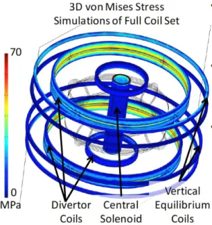
Figure 6: 3D representation of the poloidal coil set used as the basis of the finite element calculation of Lorentz forces on each coil. Colors reflect the steady state Von Mises stresses calculated as a result of currents applied to all coils. The central solenoid was included in order to assess the effects of the total field on the divertor and vertical coils and was not itself assessed.
A steady-state analysis of the Lorentz forces on the PF superconducting coils was carried out using the COMSOL multi-physics, finite element modeling software in order to assess requirements for a support structure. Of concern are both the self-induced hoop forces on the coils as well as the vertical forces between stacked sets of coils. Simulations of these forces were carried out using coupled magnetics and structural mechanics packages by prescribing current densities in each of the following coils: the central solenoid, the inner and outer divertor coils, the vertical equilibrium coils, and a circular cross section plasma with a uniform current density. Note that the central solenoid was included primarily to provide the required background magnetic field and its stresses were not evaluated. The specifics of the central solenoid coil were outside the scope of this study but were examined in [1]. The current densities and directions for each of the coils are reported in Table 1 and the imposed plasma current was set to 8.0 MA. Geometric fixed points, necessary for the calculation of static forces, were implemented on the inside bounding surface of each coil to approximate their attachment points to the FLiBe tank. Varying these fixed point locations did not significantly affect the values reported below. The VV geometry was not implemented in these simulations, as it should not affect the steady state coil forces.
Figure 6 shows both the coil set implemented for the Lorentz force calculations as well as the resultant simulated steady state von Mises stress in each of the PF coils. For all coils, the peak stress due to hoop tension was less than 80 MPa, well below the operational yield limit (~800 MPa [37]) of Inconel and of the Hastelloy backbone used in the superconducting tapes. The resulting strain would be ~0.05%, well below the critical axial tensile strain limits for REBCO HTS [31].
20
The vertical forces on each coil, due to all other coils in the simulation, are shown in Table 4. As the two outer divertor coils (PF2 and PF3) have significant currents in opposite directions, the vertical forces are the greatest on these two coils, pushing them apart vertically. If we assume that these forces are evenly distributed on the poloidal cross sections (6.1 m2) of the coils and the coils are fixed, the PF2 and PF3 coils would produce stresses of 36.6 and 43.0 MPa, respectively, well below the deformation threshold. Therefore, the challenge is simply to immobilize each coil with respect to the FLiBe tank in a reasonable manner. It should be noted that the reduced Lorentz forces is a significant advantage of being able to place the coils inside the TF coils, close to the plasma, as it minimizes the required coil currents.
Table 4: Vertical Lorentz forces on the poloidal field coil set calculated from COMSOL simulations.
Divertor coils Vertical field coils
PF1 PF2 PF3 PF4 PF5 Vertical force (MN) 20 -223 262 -76 27 Vertical cross section (m2) 2.3 6.1 6.1 7.7 8.3
Due to the low vertical Lorentz force and low-level of neutron flux at the coil locations (outside the tank [1]), the vertical equilibrium coils can be supported and attached to the TF coils using standard structural engineering practices. The two outer divertor pull coils could be constructed as a bundle – with a fixed support between and banded together on their exterior. Banding the coils together in this manner allows the bulk of the vertical stress to be compensated in the banding material which would be well within allowable stress limits as mentioned above. While modeling the stresses on these connection configurations is beyond the scope of this work, the manageable Lorentz forces on the poloidal coils suggest that simple engineering solutions should exist for structurally supporting these coils.
4. Neutronics
ARC, like all fusion reactor designs, employs a carefully designed blanket that serves the critical functions of neutron shielding, energy capture and tritium breeding. Deuterium-tritium fusion reactions within ARC will produce approximately 2.2×10²⁰ 14.1 MeV neutrons per second during full-power operation. These neutrons carry 80% of the energy produced by the DT fusion reaction. Understanding their energy deposition within the VV and coolant is vital to the success of ARC or any deuterium-tritium based fusion power plant. Radiation heating, material damage, and the tritium breeding ratio (TBR) were modeled for ARC using MCNP, a Monte Carlo photon and neutron transport code [44]. To facilitate the development of the MCNP model, coordinates from the simplified VV outline used for the ACCOME magnetic equilibrium scoping study (Figure 1) were taken as the actual first wall shape and converted to a usable MCNP geometry. The VV double wall, beryllium neutron multiplier, tank and neutron shield structures were then added around it. The neutron source location was determined by inner magnetic flux surfaces of the ACCOME magnetic equilibrium. The final design achieves a TBR of 1.08
21
± 0.004 (Section 4.3), and provides a PF coil lifetime greater than ten full-power years (FPY) (Section 4.2).
4.1 Divertor and vacuum vessel design
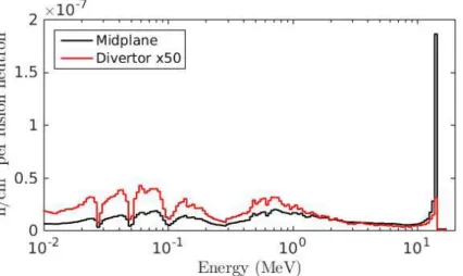
Figure 7 shows the final geometry as implemented in MCNP. Increasing the length of the divertor leg is found to reduce the high-energy component of the neutron flux in the divertor significantly. This arises from the simple geometric advantage of placing ~1 m of FLiBe along the line-of-sight between the neutron source in the core plasma and the divertor. Figure 8 shows the neutron energy spectrum both at the outer midplane (measured at the plasma facing side of the outer structural Inconel of the VV) and the divertor target volume (measured at the outer surface of the VV at the midplane of the divertor foot feature). The neutron flux in the divertor area is a factor of thirty lower than at the outer midplane. In addition, the neutron spectrum is significantly softened due to the moderation provided by the FLiBe. The reduction of fast neutron flux drastically reduces neutron damage rates, in terms of both displacements per atom (DPA) and helium production from neutron-alpha interactions. Lowering the damage rate in the divertor is highly advantageous for these high heat flux components, as materials subjected to high DPA often show a notable degradation in thermal performance [45]. Materials used in the divertor heat exhaust system must function near their thermal limits (see Section 5). Minimizing this degradation is integral to ARC’s long-term operability and, as a pilot plant, demonstrating high availability.
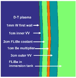
The radial build used in the MCNP model is shown in Figure 9. A non-structural 1 cm thick beryllium layer is placed on the surface of the outer VV wall. This neutron multiplier allows ARC to attain its targeted TBR, as discussed in Section 4.3. For this MCNP assessment, the same radial build shown in Figure 9 was implemented for the entire VV – including the divertor region – even though the divertor target design must be different to handle the higher heat flux (Section 5). Because the divertor is located far from the neutron source, these details do not significantly impact the neutron transport calculations. Total damage values integrated over one FPY for the entire VV for and for just the divertor region are shown in Table 5. The averaged values are high compared to what can be obtained from fast-flux neutron test facilities. However, the integrated damage rates in the divertor region may be obtained in present day fission test facilities. Levels in the range of single DPA per year found in the divertor are on the same scale as commercial fission power systems [46]. This means that materials for such a divertor may be tested under reactor level heat, plasma, and neutron loads without the need for building a high fluence DT neutron source. However, special considerations would still need to be made to account for the higher He/DPA ratio in the ARC divertor.
22
Figure 7: Cross-section schematic of the ARC design as implemented in the MCNP model. The black box indicates the region used to record divertor neutron damage level tallies listed in Table 5. With 25 cm thick ZrH2 neutron
shield plates (red) placed in front of PF1, PF2 and PF3, these coils meet the requirements for full power year lifetime (> 12 FPY, see Table 6).
Figure 8: Shown is a histogram of the neutron energies in the divertor (red) as well as the outer midplane (black). Note that the histogram bins are of variable width, selected to be uniformly spaced on a logarithmic scale. This was chosen to make key features, such as the 14 MeV peak, visible. In this figure, the divertor spectra has been increased by a factor of 50 in order to be visible on the same axis. The neutron energy spectrum at the divertor is significantly softer than at the midplane, limiting the helium buildup through (n,α) processes and lowering the DPA rates on the high heat flux surfaces.
23
Table 5: Neutron damage levels for vacuum vessel layers for one full performance year (Pfusion = 525 MW) averaged
over the entire poloidal cross section and localized to the divertor region (see Fig. 7).
Tally location DPA/yr He appm He/DPA
W inner wall average 5.4 2.4 0.45 Inner VV Inconel average 27.7 208.4 7.52 Be multiplier average 9.2 2654.6 287.7 Outer VV Inconel average 16.4 104.3 6.37 Divertor tungsten inner wall 1.9 0.7 0.38 Divertor inner VV Inconel 9.0 59.9 6.65 Divertor outer VV Inconel 4.5 24.7 5.46
4.2 Neutron shielding
The behavior of the HTS magnets under long-term irradiation, particularly the REBCO tapes used in this design, is not well characterized due to a lack of high-energy neutron exposure data. However, a rough estimate for the lifetime of the HTS superconducting poloidal field coils can be made based on Nb3Sn data, which is anticipated to have a
lower threshold than REBCO [47]. This limit, 3×10¹⁸ n/cm2 (for neutron energies > 0.1 MeV), does not represent the failure point of Nb3Sn, but rather a point at which the
critical current begins to degrade. As a result, actual coil lifetimes are anticipated to be longer than the conservative estimates shown (Table 6), in particular because the PF coils are designed to work with a significant margin to their critical current as highlighted in Table 1. The internal trim and vertical stability coils, which are exposed to a higher fluence than the toroidal or poloidal field coils, are copper and therefore do not suffer the same type of degradation. The actual neutron irradiated performance of the HTS used for this design is an open question and should be studied in future work.
The target value for superconducting coil lifetimes in this work is 10 FPYs, consistent with the original ARC design lifetime for the TF coils. It is found that this requirement
Figure 9: Radial build of the double wall vacuum vessel implemented in MCNP. A 1cm thick Be layer is placed on the surface of the outer VV layer to function as a neutron multiplier.
24
can be met by adding 25 cm thick shielding plates of zirconium hydride (ZrH2) to the
modified VV at PF coil locations. This material reduces both the neutron flux and neutron energy at the coils. The shielding was added on the interior and top/bottom surfaces of the PF coils, as shown in Figure 7. Zirconium hydride was selected because of its high hydrogen density and history of successful use in TRIGA reactors [48]. Other shielding materials may be more desirable based on chemical compatibility and safety. The key takeaway here is that adequately long lifetimes for the PF coils can be obtained by supplementing the liquid FLiBe blanket with moderate amounts of solid target shielding.
Table 6: Coil lifetimes as calculated based on a 3×10¹⁸ n/cm2 limit and damage levels from MCNP simulations with
and without 25 cm of ZrH2 shielding. Coil lifetimes are presented in full performance years, Pfusion = 525 MW. Coil set Lifetime without
shielding (FPY) Lifetime with shielding (FPY) PF1 coil 2.32 12.5 PF2 coil 6.82 76.2 PF3 coil 1.10 11.3
4.3 Tritium breeding ratio
Tritium is produced within ARC when fast neutrons impact lithium nuclei in the FLiBe blanket. For a viable fusion reactor, more than one tritium atom must be produced per fusion neutron in order to maintain the fuel cycle. With the addition of a continuous 1 cm non-structural beryllium layer as a neutron multiplier (Figure 9), the TBR of the final design is 1.08 (+/- 0.004). This value is slightly lower than the 1.1 TBR reported in the original ARC design [1] and the difference is due to the reduction in FLiBe volume as a result of the addition of the two long leg divertors.
Approximately 26% of the tritium produced within the reactor is generated in the FLiBe cooling channel within the VV wall (Figure 10). In this location, there is a higher flux of fast neutrons relative to outside the VV due to the coolant channel’s proximity to the core plasma. Future iterations on the ARC design could potentially increase the TBR by widening this channel.
25
Figure 10: A large fraction of the tritium produced in ARC is due to production in the coolant channel. Few tritium-producing reactions exist in the structural material of the VV, clearly showing the localization in the coolant channel. The tritium production drops off rapidly with distance from the core plasma as a result of the neutrons being thermalized by the FLiBe blanket.
4.4 Power deposition
Due to the VV’s proximity to the core plasma, a nontrivial portion of the neutron power is deposited volumetrically in the first wall, Inner VV Inconel, beryllium multiplier, and VV cooling channels. The distribution of neutron and photon power within the various layers of the reactor vessel are shown in Table 7, based on energy deposition tallies obtained from MCNP. Note that photon power here refers to photons generated from the 14.1 MeV fusion neutrons and not the photons radiated from the plasma. The statistical neutron distribution used to generate these energy deposition estimates is scaled to account for the DT neutron source (2.2×10²⁰ s-1), which by itself deposits 420 MW fusion neutron power (Pfusion = 525 MW) into the blanket materials. The power generated by the
blanket exceeds this amount (484 MW), primarily due to exothermic neutron on lithium-6 reactions. (A relatively small but non-negligible number of endothermic neutron capture reactions also occur at high neutron energies, as discussed below.) A primary challenge for the thermal design is that approximately ~30% of this neutron power is deposited into layers of the VV, which must be continuously exhausted into the bulk FLiBe coolant.
It is important to note that the geometry employed by the neutronics model is an approximation to the actual geometry envisioned, particularly in the divertor region. For example, the Be layer in the VV radial build (Figure 9) is taken to be present in the divertor, while in the real implementation of the ARC design, this layer would only be present in the main chamber. Due the softer neutron spectrum in the divertor (see Figure 8), the loss of the Be in the divertor would have minimal impact on TBR or DPA tallies, but energy deposition tallies may be significantly altered due to the moderating properties
26
of Be. The first ARC design study [1] showed that the Be can be replaced by tungsten to act as an effective neutron multiplier – and tungsten is a likely design choice for ARC’s divertor targets (Section 5.2). A follow-on MCNP study is needed to do assess the overall impact.
The MCNP simulations and power deposition estimates presented here represent a significant refinement compared to the original study [1] in which the total thermal power generated in ARC was estimated to be 708 MW. The refined calculations project to 630 MW thermal power. This difference is traced to the inclusion of endothermic neutron interactions with elements such as fluorine, which have relatively high threshold energies. These reactions will ultimately produce a mix of isotopes in the blanket and transmutate original atoms to other elements (in the case of fluorine, to oxygen, carbon and nitrogen). The cost for driving this process is a net loss of approximately ~1 MeV per primary 14.1 MeV neutron. This gradual shift over time of the isotopic make-up of FLiBe compared to startup is something that has not yet been analyzed; it would likely impact molten salt chemistry and drive the requirements for continuous monitoring and replacement of FLiBe. TBR could be impacted as well, affecting blanket material choices and design.
Table 7: Power deposition in each of the material layers modeled in MCNP for 420 MW fusion neutron power. Note that parameters at top are for the entire VV (main chamber and divertors); parameters at bottom are for one divertor only.
Layer Power (MW) Volume (m3) Average volumetric
heating (MW/m3)
Tungsten inner wall 8.4 0.35 24.1 Inner VV Inconel 39.6 3.50 11.3 Cooling channel FLiBe 77.7 7.04 11.0 Be multiplier 22.4 3.55 6.3 Outer VV Inconel 78.9 10.7 7.4
Bulk FLiBe 255 241 1.1
PF Coil Shielding (see Fig 7) 1.9 49.2 0.04
Divertor Region
Divertor tungsten inner wall 0.77 0.08 9.6 Divertor inner VV Inconel 3.10 0.82 3.8 Divertor cooling channel 7.12 1.66 4.3 Divertor Be multiplier 1.53 0.84 1.8 Divertor outer VV Inconel 5.50 2.57 2.1
5. Heat exhaust management system
For the ARC heat exhaust system to be viable, it must ultimately accommodate a wide variety of performance requirements and constraints on materials selection, thermal characteristics, and the pumping power needed for active cooling. Particular attention must be paid to the thermal management of the divertor due to the high heat fluxes that impinge upon those surfaces. As a starting point, we assume that the projected