HAL Id: tel-02534996
https://tel.archives-ouvertes.fr/tel-02534996
Submitted on 7 Apr 2020HAL is a multi-disciplinary open access
archive for the deposit and dissemination of sci-entific research documents, whether they are pub-lished or not. The documents may come from teaching and research institutions in France or abroad, or from public or private research centers.
L’archive ouverte pluridisciplinaire HAL, est destinée au dépôt et à la diffusion de documents scientifiques de niveau recherche, publiés ou non, émanant des établissements d’enseignement et de recherche français ou étrangers, des laboratoires publics ou privés.
tether shape control
Matheus Laranjeira Moreira
To cite this version:
Matheus Laranjeira Moreira. Visual servoing on deformable objects : an application to tether shape control. Automatic. Université de Toulon, 2019. English. �NNT : 2019TOUL0007�. �tel-02534996�
Acknowledgements
First of all, I would like to thank each member of my jury for giving me the honor of assessing my work. Thanks to Yvan Petillot, professor at the Heriot-Watt University, for chairing my jury. Thanks to Luc Jaulin, professor at ENSTA Bretagne, and to Fran¸cois Chaumette, Inria senior research scientist, for the time they spent analyzing this thesis and for all the remarks and high-quality feedbacks given in their reports. Thanks to Viviane Cadenat, associate professor at Universit´e de Toulouse III, to Vin-cent Creuze, associate professor at Universit´e de Montpelier, and to Andrea Cherubini, associate professor at Universit´e de Montpelier, for accepting to be members of the jury and for their interest in my work. Thanks to the invited members of my jury, David Navarro-Alarcon, assistant professor at The Hong Kong Polytechnic University, Yves Chardard, CEO of the Subsea Tech company, Jan Opderbecke, head of unit for underwater systems at Ifremer, and Lorenzo Brignone, head of the underwater robotics laboratory at Ifremer, for their useful comments.
I also thank the French Sud region and the Subsea Tech company for their financial support.
I would like to thank my supervisor, Vincent Hugel, and advisor, Claire Dune. They introduced me to the scientific and academic world. Their advices and criticism allowed me to advance during the thesis. I thank them for their availability and support. Thanks to all the members of the laboratory for all the discussions and interesting feedbacks. Thanks to Sabine Seillier and C´edric Anthierens for their assistance during the experimental phase of this thesis.
I thank my former colleagues at the office: Minh, J´erome, Nicolas, Ornella, Jean-Baptiste, Hoang Anh... The pleasant working environment and good mood helped me a lot to keep my optimism even in harder times. Thanks to Minh for his support during my first experiments in the summer of 2016. Thank you Anh for your kindness and providential help during the experiments with underwater robots. Thanks for the cayenne peppers. It will be amazing to see them grow and have fresh peppers this summer. Thank you Jean-Baptiste for presenting me this wonderful region that is the Provence and the Mediterranean coast and for the interesting discussions about the latin languages. Thanks for the Slivovica. It will be nice to appreciate it next winter.
I would also like to thank my family. My father, Agnaldo, my sister, Paloma, and my bother, Saulo, for all the good times we spent together and their support, even at a distance. A special thanks to my mother, Magali, for being present at some key moments in this thesis.
Thanks to Salima and Edmond for the restoring weekends and for being present in my thesis defense. Thanks to Marisa for all the support during the last months.
I have to enormously thank Dorothea, my partner and great love. Thank you for always listening to me and providing endless support and encouragement. Thanks also for accepting to be the official graphic designer of this thesis. Your work significantly improved the aesthetic quality of this manuscript. For all your help in everyday life, I do not know how to thank you. I believe you will have to do a thesis as well. But I ask the good Lord not to.
Contents
Contents 1
Glossary 4
Introduction 7
1 State of the Art on Tether Management 11
1.1 The Underwater Environment . . . 12
1.2 Underwater Robots . . . 13
1.2.1 Autonomous Underwater Vehicles . . . 13
1.2.2 Remotely Operated Vehicles . . . 14
1.3 Tethers . . . 16
1.3.1 Utility . . . 16
1.3.2 Buoyancy . . . 17
1.3.3 Cross-section . . . 17
1.3.4 Models . . . 20
1.4 Tethers and Deformable Objects Management . . . 21
1.4.1 Underwater Applications . . . 21
1.4.2 Terrestrial and Aerial Applications . . . 23
1.4.3 Synthesis of Existing Cable Management Strategies . . . 26
1.4.3.1 Passive and Active Cable Management Strategies . . . 26
1.4.3.2 Classification according to Cable Perception and Mod-eling techniques . . . 28
1.5 Our Scientific Focus: Vision Servoing of a Pair of Robots in a Chain of Mini-ROVs . . . 30
2 System Modeling 33 2.1 Tether Model . . . 33
2.1.1 Catenary Equation . . . 33
2.1.2 Catenary Parameter . . . 35
2.1.3 Catenary Parameter Constraints . . . 37
2.2 Robots Model and Configuration . . . 38
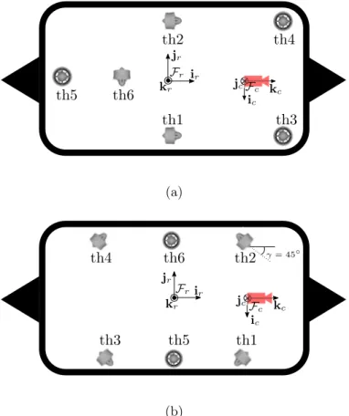
2.2.1 Thruster Configuration and Allocation Matrix . . . 39
2.2.2 Kinematic Model of a mini-ROV . . . 46
2.3 Pair of Robots Connected by a Tether . . . 49
2.3.1 Catenary Model Applied for Tethered Robots . . . 49
2.3.2 Tether Attachment Points and Robots Kinematics . . . 52
2.4 Conclusions . . . 56
3 Underwater Perception of the Tether 57 3.1 Camera Configurations and Assumptions . . . 57
3.2 Camera Modeling . . . 60
3.2.1 Image Formation . . . 60
3.2.2 Camera Exposure and White Balance . . . 60
3.2.3 The Pinhole Camera Model . . . 62
3.2.4 Intrinsic Parameters . . . 63
3.3 Tether Detection . . . 65
3.4 Catenary Features Estimation . . . 67
3.4.1 Catenary Equation in the Camera Frame . . . 67
3.4.2 Catenary Projection on the Image Plane . . . 69
3.4.3 Catenary Curve Fitting . . . 70
3.4.3.1 Gauss-Newton Algorithm . . . 71
3.4.3.2 Study of the Gauss-Newton Jacobian Singularities . . . 72
3.4.3.3 Particular Case of Remote Points . . . 74
3.4.3.4 Gauss-Newton Improved Algorithm . . . 75
3.4.3.5 Initial Guess of Catenary Shape for Gauss-Newton . . . 84
3.5 Results . . . 92
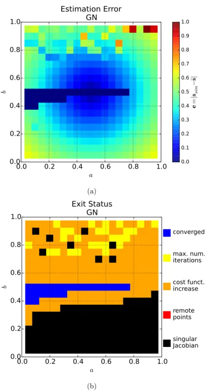
3.5.1 Focus on Feature Vector Estimation Error . . . 92
3.5.2 Study Cases in a Simulated Environment . . . 97
3.5.3 Discussion . . . 106
3.6 Conclusions . . . 108
4 Tether Shape Control 109 4.1 State of the Art on Vision-Based Control . . . 110
4.1.1 Rigid Objects . . . 110
4.1.2 Deformable Objects . . . 112
4.2 General Control Scheme . . . 115
4.3 Catenary-Based Interaction Matrices . . . 117
4.4 Follower Robot Control using Tether Visual Feedback . . . 125
4.4.1 Preliminary Results with Terrestrial Robots . . . 126
4.4.1.1 Catenary-Based Visual Servoing for Terrestrial Robots 126 4.4.1.2 Comparison of Catenary-Based Control with Image-Based Visual Servoing . . . 130
4.4.2 Underwater Tether Shape Regulation while Leader Robot is Mo-tionless . . . 138
4.4.2.1 Visual Servoing Control with 3 × 4 Interaction Matrix . 139 4.4.2.2 Sum of Controllers . . . 141
Contents 3
4.4.2.4 Comparing Follower Robot Trajectories . . . 147 4.4.3 Underwater Tether Shape Regulation while Leader Robot Moves 148
4.4.3.1 Neglecting the Leader Velocity on the Follower Robot Command . . . 149 4.4.3.2 Including the Leader Velocity on the Follower Robot
Command . . . 154 4.5 Follower Robot Control using Tether Visual Feedback from Both
Cam-eras - Underwater Case . . . 156 4.6 Discussion . . . 161 4.7 Conclusions . . . 163
5 Conclusions 165
5.1 Summary . . . 165 5.2 Perspectives . . . 166
A Position and Orientation Representation 169
B Expression of the catenary parameter C 171
C Kinematic Equations with Twist Matrix: General Case 177
D Catenary Derivatives 179
E Preliminary Results with Terrestrial Robots 181
F Interaction Matrix Test Protocol 195
G Scientific publications, Workshop Participations and Scientific
Popu-larization Activities 201
H R´esum´e en fran¸cais 203
Bibliography 223
Glossary
General rules
a a scalar in the image plane is represented by a lowercase letter A a scalar in E3 is represented by an uppercase letter
a a vector is represented by a bold lowercase letter A a matrix is represented by a bold uppercase letter Mathematics
En Euclidean space with n dimensions
Fa a generic Euclidean reference frame Fa(Pa, ia, ja, ka) consists of an
origin Pa and an orthogonal basis (ia, ja, ka)
p the bold lowercase letter p is reserved to represent a vector containing the normalized coordinates of an image point. For example, pa =
[xa ya 1]T represents an image point a in the camera frame
Pa a generic point in the Euclidean space E3 is noted Pa, where the
subscript a identifies the point
PbPa a vector defined by starting point Pb and end point Pa bP
a the overlined bold uppercase letter P is reserved to represent a vector
containing the Cartesian coordinates of a 3-D point. b{P
bPa} = bP
a= [bXabYa bZa]T represents the 3-D point Pa in frame Fb andP2P1
dt
o
Fb
the derivative of vector P2P1 with respect to frame Fband expressed
in frame Fa
˙
bP
a the derivative of vector PbPa with respect to frame Fb and expressed
in frame Fb bP
a the bold uppercase letter P is reserved to represent a vector
contain-ing the homogeneous coordinates of a 3-D point. bP
a = [bPa 1]T
represents a 3-D point Pain frame Fb bR
a a 3-D rotation matrix from frame Fa to frame Fb bM
a an homogeneous transformation matrix from frame Fa to frame Fb bv
a the velocity screw vector bva = [bνa,bωa]T of point Pa expressed in
the coordinate frame Fb. bνa and bωa are, respectively, the linear
and angular components of the velocity vector
va the generic velocity screw vector va = [νa, ωa]T of point Pa not
projected in any coordinate frame. The linear velocity of Pais noted
νa and the angular velocity of frame Fa with respect to the world
Introduction
Unmanned mobile robots are well suited to explore environments considered too costly, time consuming, and hazardous for human inspection. They execute a wide variety of tasks such as gathering samples or monitoring and maintenance of structures in inaccessible sites. In some cases, when the explored environment is well structured, these robots can operate in autonomy, without any human intervention, being mostly employed in survey applications. However, autonomous navigation in unknown spaces and autonomous manipulation requiring physical contacts with unstructured environ-ments without human supervision represent technical and technological challenges that remain to be addressed.
Many robotic tasks require continuous human intervention to be carried out. In such cases, the decision-making and intelligence of operation is the human responsi-bility, while the robot is limited to execute the low level tasks. Teleoperation systems are required to allow human operators to control the robots with the aid of visual and other sensory feedback. Teleoperation systems can be divided into two main categories: wired and wireless communication. Wireless teleoperation is preferable in some robotic applications, since it offers the robot more freedom of motion and flexibility in naviga-tion. Nevertheless, a wireless link may be subject to interference and signal loss that degrade the reliability of data exchange with the robot. Therefore, the use of tethers has advantages in applications where robust data communication is a priority and its interruption can lead to the loss of the robot and mission failure.
Applications where the use of tethers is preferable instead of wireless communica-tion include, for example, urban search and rescue operacommunica-tions (Fukushima et al., 2000; Perrin et al., 2004), planetary geologic survey (Tsai et al., 2013), underwater missions (McKerrow and Ratner, 2007) and sewerage (Reverte et al., 2011). Specifically in the case of underwater operations, wireless communication is even more complicated, since electromagnetic waves are strongly attenuated in water and acoustic subsea commu-nications have a very low bandwidth and significant time delay, which represents a considerable obstacle to robust teleoperation (Marani et al., 2009).
The main advantage of using tethers is the provision of a fast and stable commu-nication link. In addition, tethers can transfer power, which makes it possible to carry out longer operations with energy consuming payload and enable vehicle downsizing thanks to the absence of batteries. Another advantage of tethers is that they can be used as a mechanical support for robots exploring hard-to-reach areas as cliffs, caves, crevices and other steep terrains (McGarey et al., 2016b). Nevertheless, tethering also
have important shortcomings. Tethers are known to limit the robot workspace and they may become entangled with obstacles or with other fellow robots, leading to im-mobilization. The energy transfer by wire may also represent a constraint to large robot displacements since a very long cable increases the losses by Joule heating. A compromise must be found between the power demanded by the robot and the size of the cable: for a better power flow, thicker cables are needed. However, the thicker the cable, the more rigid it is and greater torsion efforts it applies on the robot, which will require more power to compensate them.
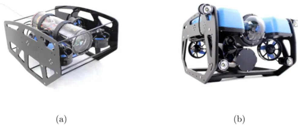
In this thesis, we are interested in the use of small tethered underwater robots, also called mini remotely operated vehicles (mini-ROVs), in the context of exploration of shallow waters, with less than 10 meters of depth. The ROVs are linked to a surface vessel by a tether (also called umbilical) that ensures energy supply and data transfer. Typical ROVs generally weigh some hundred kilograms and are powerful electrome-chanical machines that require significant human and material resources to be deployed. They have a working depth between 1,000 and 6,000 meters and can move away several tenths of kilometers from their base. The logistical difficulties of deploying large un-derwater robots led to the development of mini-ROVs, that weigh a few kilograms and are low-power demanding. They are able to explore shallow waters, caves and some wrecks that are not accessible to typical ROVs. However, these light-weight and less powerful vehicles are much more sensitive to the disturbances engendered by a long tether, which can cause unbalance and make them difficult to maneuver. Mini-ROVs are thus limited to displacements around the surface vessel, which consequently limits the exploration of shallow waters, since the vessel cannot get too close to the coast.
The Cosmer Laboratory and the SUBSEA-TECH company, a partner and co-funder of this thesis, came together in reflections and discussions on the possible strategies of underwater robotic teleoperation in coastal areas. Thereby, the idea of using mini-ROVs serially linked with a tether arose: a group of small-size identical robots are distributed all along the tether (see Figure 1). All robots forming the fleet have the same architecture, the same set of sensors and actuators, hence the same motion capability. Together, the small robots can compensate the disturbances of a long tether and allow the leader robot to behave as if it were in the vicinity of the base. Moreover, this chain of robots can work as a sensor network that have a distributed perception of the underwater environment. Mapping of currents and seabed can be achieved with this fleet of robots that can collect data and share informations in real time thanks to the wired connection. Depending on the situation, the fleet could also be organized in ways other than serial, as triangular or square grids, in order to enlarge the covered area.
The objective of this PhD thesis is to investigate how to control the shape of a section of tether linking a pair of robots, a leader and a follower, as it is illustrated by Figure 1. The general idea is that the leader robot freely explores its surrounding, as if it was not attached to anything, while the follower robot is expected to manage the tether shape from its embedded sensors feedback so that the tether does not hamper the leader movements. We propose to use only standard sensors commonly embedded in the mini-ROVs while the tether itself will not be modified nor instrumented.
state-of-the-Chapter 1
State of the Art on Tether
Management
There are two types of unmanned underwater vehicles: remotely operated vehicles (ROVs) and autonomous underwater vehicles (AUVs). ROVs communicate continu-ously with a surface vessel thanks to a physical link called umbilical or tether, due to the low-bandwidth of underwater wireless communication. AUVs are completely autonomous and previously programmed to execute specific mission with very little communication with the surface vessel.
Despite the recent development of techniques of autonomous navigation and task execution, a large number of underwater robotic missions are still carried out by tele-operation. The tether provides a reliable communication link and power supply that enables the fulfillment of long-term missions. There are different types of tethers, de-pending on the type of mission and deployed robot. Heavy, thick and rigid tethers are used to transfer data and huge amounts of energy to work-class ROVs that operate in deep sea. Thinner and more flexible tethers are used to provide data exchange to large ROVs that have embedded batteries, or also to provide energy to low power-consuming ROVs. Tethers are thus an important element in underwater robotics operations, and a large number of missions that require continuous human intervention could not be achieved without them. Tethers, however, also bring with them additional problems to robotics operation, since they limit the robot workspace and can be entangled with objects in the environment, leading to robot immobilization and, consequently, mission abort.
Tether management is one of the most challenging issues in operations using teth-ered robots. In this Chapter we address the current strategies that deal with the control of umbilicals. We start by describing the underwater coastal environment where our system will be deployed. Then, we continue by defining the different types of robots and tethers that are used in underwater operation. Next, we give some details about the existing strategies of tether and deformable objects handling in the context of un-derwater application, which can be also extended to others domains of application. Finally, we present our strategy of tether management for mini-ROVs that operate in
underwater cluttered coastal zones (less than 10 meters deep) while being as far as possible from the surface vessel.
1.1
The Underwater Environment
Coastal areas are the boundaries between the marine and continental domains. These are important areas in terms of both marine and terrestrial biodiversity as well as in terms of convergence of oceanic and continental processes that play a major role in the determination of geomorphological, geochemical and climatic changes. The coasts are very attractive, as evidenced by the strong anthropomorphization of the littoral zone. It is estimated that currently more than 60% of the world’s population (3.8 billion people) live in coastal area (less than 150km from the coast). This high concentration of population is due to a considerable economic activity, particularly in the fisheries sector, aquaculture, trade and energy, but also due to the booming touristic sector.
With respect to the underwater environment, the abundance of light in the first meters of depth makes the environment the home of a large range of species. It is also an important area of reproduction, as it is, for example, the case of estuaries and coral reefs. The coastal marine environment shelters fragile ecosystems that should be constantly monitored with the aim of preserving their balance. This surveillance is all the more important since coastal ecosystems are often affected by pollutants generated by ship traffic and liquid waste emission of cities.
Seawater can be characterized by thermophysical properties as density, temperature and salinity. The density of surface seawater ranges from about 1020 to 1029kg/m3, depending on the temperature and salinity. At a temperature of 25◦C, salinity of 35g/kg
and pressure of 1atm, the density of seawater is 1023.6kg/m3(Nayar et al., 2016). Deep in the ocean, under high pressure, seawater can reach a density of 1050kg/m3or higher. In the Mediterranean sea, the surface temperature ranges from 13◦C to 25◦C annually.
Salinity varies between 38.4 and 41.2g/kg and its density is around 1027kg/m3. Water
density slightly varies with depth and can be considered constant in the first 30 meters. The sea profile can be schematically divided into different areas based on the wave propagation, and the hydromorphodynamic processes involved (see Figure 1.1). The wave base is the depth from which waves can interact with the seabed moving sand shoreward. It is normally characterized as a half of the wavelength. At depths greater than half the wavelength, water motion is less than 4% of its value at water surface and can be neglected. The wave base depth is generally between 1 and 30 meters. The nearshore zone extends from the wave base depth until the waves break point. The surf zone (or breaker zone) extends from the waves break point until the shore line. This is a dynamic area associated with wave-generated currents, including longshore, undertow and seaward moving rip currents. Finally the swash zone represents the portion of beach alternately covered and discovered by the water.
We are interested in exploring the nearshore and breaker zones, which are both areas where intense sea currents take place. As we will see in the next Sections, most
Underwater Robots 13
Figure 1.1: Profile or cross-section of a typical wave-dominated beach showing the near-shore zone, the surf zone, and finally the swash zone. Courtesy of Short and Woodroffe (2009).
of the time, unmanned underwater vehicles are equipped with proprioceptive and exte-roceptive sensors, such as inertial measurement units (IMU), sonars, cameras, doppler velocity-log (DVL), pressure gauge, etc. In coastal environments, inertial measure-ments become noisier due to accelerations produced by the currents on the robot. This leads to a gradual drift of position estimation in inertial navigation systems. The image feedback of the cameras are also affected by the presence of current, since they put the seabed sediments in suspension, rendering the water more turbid. Camera visibility is already limited to some tenths of meters in clear waters due to light absorption (all colors are absorbed, except blue). In turbid waters, the presence of sediments can fur-ther degrade the image quality of cameras. The following Sections deal with a survey of existing solutions in order to design a relevant robotic system that could be used to explore such challenging environments.
1.2
Underwater Robots
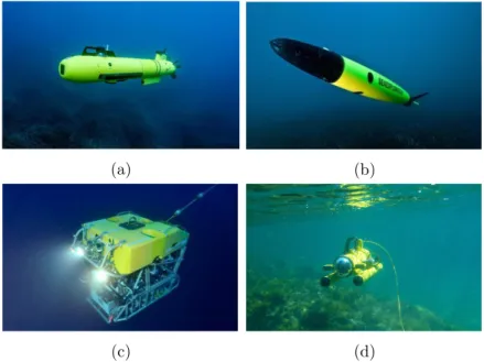
There are different categories of underwater robots that are each one suited for the execution of specific tasks at a given depth range (see some examples in Figure 1.2).
1.2.1 Autonomous Underwater Vehicles
In survey missions, where large areas shall be covered and inspected by robots (a few square kilometers in a day, for example), the AUVs (Autonomous Underwater Vehicles) are commonly employed. They are untethered robots designed to cover large travel distances thanks to their hydrodynamic shape (usually in torpedo form) and to collect data in autonomy for post processing. Examples of application are localization
missions of wreckages of missing airplanes or detailed mosaicking of the seafloor for the oil and gas industries (Wynn et al., 2014). An important subclass of AUVs are the underwater gliders, that use small changes in their buoyancy in order to move up and down in the ocean. This vertical displacement generates a forward motion thanks to the use of flying wings and to the control of the vehicle pitch by movable internal ballast (usually battery packs). Vehicle steering is accomplished either with a rudder or by moving internal ballast to control roll. They are generally used in oceanography research to collect chemical and physical measurements of seawater in ocean sampling missions that range from hours to weeks or months, with up to hundreds of kilometers of range (Inzartsev and Alexander Pavin, 2009, chap. 26). Since they are deployed for missions of long duration (up to several months) and large displacement (hundreds of kilometers), their localization is less accurate than other AUVs during the cyclic diving period.
(a) (b)
(c) (d)
Figure 1.2: Some examples of French underwater robots. (a) the AUV A9 from ECA robotics. (b) the AUV glider Sea-Explorer from Alseamar. (c) Victor 6000, an Ifre-mer work-class ROV dedicated to scientific ocean research in deep waters. (d) the observation-class mini-ROV observer from Subseatech.
1.2.2 Remotely Operated Vehicles
ROVs are employed in missions where continuous human intervention is required. They are highly maneuverable vehicles that are operated by a crew aboard a vessel or floating platform. The connection between the robot and the crew is made possible thanks to a tether or an umbilical cable that is used along with a tether management system (TMS). ROVs are often designed to execute inspection, repair and maintenance of sub-sea structures in deep water. Some fields of applications are the offshore hydrocarbon
Underwater Robots 15
extraction and the scientific research studying deep sea ecosystems and archaeolog-ical sites. There are three main categories of ROVs, based on the vehicle size and capabilities (Christ and Wernli Sr, 2013):
1. Work class ROVs: Vehicles in this category are generally heavy electrome-chanical machines (over 1000 kg). These robots are used to execute maintenance and construction tasks of huge underwater structures, typically in the oil and gas industry or in the heavy civil engineering. Due to the necessity of large amounts of force, the vehicle propellers and manipulators are hydraulically powered. They are designed to be deployed in waters deeper than 3000 meters. This deep depth can be achieved thanks to bulky pressure housings that protect the whole system from high pressure. The size and weight of the vehicle implies that they have to be deployed from large surface vessels with a specific launch and recovery system (LARS) that looks like a crane. In such operations, the amount of exposed cable is so important that a dedicated tether management system (TMS) is required to reduce the disturbances generated by the cable on the robot.
2. Mid-sized ROVs: These vehicles weigh from 100 kg up to 1000 kg. They are designed to operate in intermediate depths around 1000 meters, being thus more compact than the work-class ROVs. They are also generally all-electric vehicles (powering locomotion and sensors) with some hydraulic power for the operation of manipulators. Their missions are similar to work-class ROVs, but operating at lower depths. They also need to be deployed by a LARS and depending on their weight and size, smaller surface vessel and fewer crew members are needed, reducing the operation costs.
3. Observation class ROVs: These robots go from the smallest vehicles to those wighting 100 kg. They are employed in depths lower than 300 meters. They are completely electric machines, DC-powered and much less expensive than the other class of ROVs. They are mainly used for observation missions, for inspection in offshore industry or for oceanographic and archaeological research. Some of them are equipped with electrical manipulator arms to perform dexterous tasks (as biological sampling or archaeological excavation). The arm is equipped with specific tools such as vacuum gripper, brushes or pliers. The lighter vehicles within this class are typically hand launched, and can move freely from the surface with manual handling of the tether.
In this thesis we focus on the use of mini-ROVs, a sub-category of the observation class. Usually, mini-ROVs are used in places such as a sewer, pipeline, small cavities, very shallow waters and other cluttered spaces. One person can carry the complete ROV system (robot and tether) up to a small boat, deploy it and complete the job without outside help. A remarkable advantage of using mini-ROVs is the low cost of the operation (Wernli and Christ, 2009). Actually, the reduction of the operating costs is a main goal in underwater robotics research, since the mobilization of huge structures (host ship and crew) represents an important part of the mission charges. In the cases
of survey or light manipulation missions, mini-ROVs can be used in cooperation with USVs (unmanned surface vessels), as described in Shimono et al. (2015); Conte et al. (2018). This kind of system eliminates the need of an on-board crew, that can in return operate onshore via a radio-link. The reduced costs facilitate the access to underwater intervention for safety and security operations in civil structures such as ports, channels and dams (Molchan, 2005), as well as for many other scientific domains, such as oceanography (Smolowitz et al., 2015) and archaeological (L’Hour and Creuze, 2016) research. Normally, in such fields, the tasks of surveying and sampling are made by a professional diver. However, the operating complexity, medical problems, high costs and limited time of diving have led to the development of alternative robotic solutions in which the use of mini-ROVs plays a relevant role. These robots are operated up to some hundreds of meters away from the surface vessel.
At these distances, important dragging forces are applied to the tether which con-siderably disturbs the motion of the mini-ROV. Therefore, even for these small robots, a system that could manage the tether is required. Besides, this system should be able to detect or prevent tether entanglement. This necessity is even more important if the mini-ROV is deployed in confined or cluttered environments. In order to achieve a functional tether management for mini-ROV we must have some knwoledge about the tether properties. Another objective is to minimize the forces that the tether applies on the ROV. In the next section we focus on the different types of tether and their physical properties.
1.3
Tethers
In order to understand the forces that a tether applies on a mini-ROV, the interaction between the robot motion and the cable shape should be modeled. First we will give some definitions about ROV usual tethers. Secondly we will investigate the influence of the tether cross-sectional area on the system design and then present some existing cable models.
1.3.1 Utility
ROVs require an electromechanical cable that provides mechanical support, power sup-ply and data exchange with the surface vessel. In work-class and middle-class ROVs, a tether management system (TMS) is needed to regulate the thousands of meters of cable deployed and disturbances caused by the surface vessel motion. The cable linking the surface to TMS is termed the umbilical, while the cable from the TMS to the submersible is termed the tether. The umbilical cable is used to reach the operational depth while the tether cable allows the ROV to make excursions at that depth for a distance of around a few hundred meters away from the TMS. ROVs of various sizes and categories can use a TMS, with the constraint of having a crane on board the ship that can move the whole system (robot and TMS) from the deck to the splash zone.
In the case of mini-ROVs, since their operational depth is limited to some hundreds of meters, no TMS is needed and the robot remains in the vicinity of the surface vessel.
Tethers 17
Thus, we will always use the term tether when making reference to a cable linking a mini-ROV to a surface vessel, base station or fellow robot. The diameter of the cable is the dominant factor in overall vehicle drag. Therefore, minimizing cable diameter is an important part of ROV design and operation. Some advanced ROVs carry their own power sources and only require a communication link to the surface vessel through an expendable fiber-optic cable (Brignone et al., 2015). The umbilical cable is generally steel jacketed, while the tether cable uses synthetic fibers to maintain the required buoyancy (neutral, slightly negative or positive).
1.3.2 Buoyancy
The tether buoyancy in water is also an important aspect to consider. There are three buoyancies to consider:
• Positive: when the tether has a lower density than water and therefore rises. • Neutral: when the tether has the same density than water and therefore remains
in suspension in the water column.
• Negative: when the tether has a higher density than water and sinks.
Some examples of tethers are depicted in Figure 1.3 and their physical properties can be found in Table 1.1.
Which tether to choose depends on the application. For example if the ROV is to operate on the sea floor it would be preferable to use a neutral or positive tether to keep it from dragging along the sea floor and potentially becoming entangled with objects. A negatively buoyant tether has fewer applications and are commonly employed in deep water environments, or areas with snagging hazards near the surface of the water, such as under-ice teleoperations (Bowen et al., 2012; Katlein et al., 2017).
Tether diam. (m) lin. density (kg/m) buoyancy
Fathom 7.6 × 10⁻³ 4.3 × 10⁻² neutral
Novasub 7.4 × 10⁻³ 5.4 × 10⁻² negative
µlinx 8.0 × 10⁻⁴ 7.0 × 10⁻⁴ negative
Table 1.1: Tethers physical properties shown in Figure 1.3: diameter, linear density and buoyancy in fresh water.
1.3.3 Cross-section
Work class ROVs have power provided in alternating current (AC), which is transmitted through the umbilical from the surface vessel to the cage and then from the cage to the ROV through the tether. When it reaches the robot, the electrical power is converted to direct current (DC) to power the electronics. Video and data are often transmitted through optical fibers in order to reduce the electromagnetic disturbances caused by the AC power transmission.
outer jacket Vectran fiber braid strength member a pair of twisted shielded cables 2x24 AWG power conductors 2x0.5 mm2 (a) outer jacket Kevlar strength fibers Polyethylene inner jackets 26 AWG stranded twisted pairs Dacron filler fiber (b) outer jacket aramid yarn acrylate coating silica clad silica core 0.8 mm (c)
Figure 1.3: Some examples of tethers used by mini-ROVs. (a) the tether model DLR-1P20-2C50 from Novasub for power supply and data transfer. (b) the Fathom tether from BlueRobotics that carries four pairs of 26 AWG wire for data exchange. (c) the µlinx 50 OM3 tether from OFS optics is composed of a multimode 50 µm optical fiber for data transfer.
While mid-sized and work class ROVs use AC current for power transmission through the umbilical and then a combination (AC and DC) along the tether, most observation class ROV systems use exclusively DC current for power transmission. The delivered power should be sufficient to operate all the electronics and thrusters. The propulsion of the vehicle must be powerful enough to overcome its own drag force but also that of the tether. Therefore, the tether length may be critical in determining the available power for vehicle displacement. A too long tether can generate too much drag force that would lead to the vehicle immobilization. In addition, long cables also de-creases the available power due to losses caused by Joule effect. The maximum tether length for a given power requirement is a function of the voltage, the size and the resistance of the conductor:
P = U
2A
ρL (1.1)
where P is the delivered power, U is the voltage, A is the cross-sectional area of the conductor, ρ is its electrical resistivity and L is the tether length. The maximum range of the robot is hence limited by a maximum tether length above which the most part of the delivered power is dissipated in heat through the cables (see Figure 1.4). In the
Tethers 19
case of mini-ROVs, this limitation is even more restrictive due to the low voltage of the embedded electronic devices and thrusters (about 12 volts).
Figure 1.4: The maximum tether length for a given voltage V and a given cable cross-sectional area A. Extracted from Christ and Wernli Sr (2013).
The ROV’s tether is typically the highest drag item on the ROV system. The drag produced by the ROV is based upon the following formula (Christ and Wernli Sr, 2013):
Dtether =
σAtLtVt2Cdt
2 (1.2)
where σ is the ratio between the density of water and the gravitational acceleration; Cd is the non-dimensional drag coefficient, ranging from 0.8 to 1 based on the
cross-sectional area of the tether profile (A); L is the tether length; V is the tether relative velocity with respect to water and AL is the characteristic area on which Cdis applied.
The robot drag is calculated in the same way and the system total drag is then:
Dtotal=
σAtLtVt2Cdt
2 +
σAvLvVv2Cdv
2 (1.3)
The total drag increases proportionally with the tether length for a given cross-section (see Figure 1.5).
Figure 1.5: Tether drag versus tether length. Extracted from Christ and Wernli Sr (2013).
The demanded power needed to compensate the total drag is calculated as follows:
PD = DvVv+ DtVt. (1.4)
It is linearly proportional to the tether length and to the cube of the velocity, which means that for a given maximum velocity, the longest the cable, the highest the power needed to displace the vehicle and tether. From equation 1.1, in order to increase the available power, for a given length, we have to increase the cable cross-sectional area, which directly impacts the power needed to compensate the dragging force. Then, a trade-off has to be found between the maximum velocity and maximum reach of the system with reasonable power requirements.
1.3.4 Models
In order to be able to manage the motion of a cable that is freely deployed in seawater in presence of currents, tides and waves, we need to estimate the tether shape. To do so, there are two solutions. The first one is to add sensors at the attachment points and all along the cable, as is the case of Smart Tethers (Frank et al., 2013). These tethers are designed to offer a real-time GPS location of the ROV using non-acoustic tether shape measurements. Several nodes are embedded along the tether cable to provide local orientation and depth. This information is used to estimate the current tether shape and ROV heading and position with a 10-30 Hz refresh rate. Similarly, optical fiber may also be used to give visual feedback of the tether shape (Childers et al., 2010). The second solution, if we consider a non-equipped tether, is to use a parametrized model of the cable. A cable can be physically described by its attachment points, a cross-sectional area, length, linear density and axial, flexural and torsional rigidities. Cable modeling is useful to help to understand cabled structure statics and dynamics as well as to design carrying cables for suspension bridges, intercontinental communication cables, cable-driven robots, and to design umbilicals and tethers providing power supply and data transfer for teleoperated robots.
The most complete cable model in the air relies on the Irvine equation (Irvine, 1981) that takes into account both the elasticity and the deformation of the cable due
Tethers and Deformable Objects Management 21
to its own mass and has been shown to be very realistic (Merlet, 2018c). This model assumes that the cable lies in a vertical plane, the cable plane, and is therefore a 2D model. However, this model is complex to use in a kinematic analysis (Merlet, 2018c). In Howell (1992), the problem of low-tension cables is investigated for underwater ap-plications and several models that consider or ignore the cables elasticity are studied. The equations of motion for a cable are nonlinear and strongly coupled for complete cable models. Other numerical models of underwater umbilicals and tether were ad-dressed in Buckham (2003); Buckham et al. (2003), where a tether lumped mass model is addressed. If we consider inextensible (nonelastic), perfectly flexible and subjected to a uniformly distributed load, a widely spread cable model is the catenary curve (Irvine, 1981). Analytic solutions are difficult to obtain for complete models, and numerical approximation techniques are often necessary. In the simplified case of a catenary, analytic solutions are available.
In the next section we will see that other simplified models were used for tether and deformable objects shape control strategies such as parabolas, splines and circle arcs. For real-time robotic control these approximated parametric models have the great advantage of speeding up the computational time of the control loop, although being limited to some environmental and operational assumptions.
1.4
Tethers and Deformable Objects Management
This section focuses on existing strategies of tether management for underwater and mobile robots in general. Since the tether can also be seen as a deformable object, this section will also address some techniques of deformable objects handling that could be applied to tether management.
1.4.1 Underwater Applications
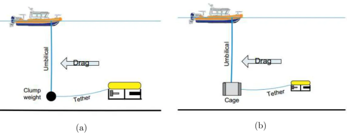
This subsection deals with tether management systems (TMS) that are typically used for work-class and middle-class robots. As depicted in Figure 1.6, the TMS is placed at the junction between the end of the umbilical and the beginning of the tether (Hawkes and Jeffrey, 1987; Abel, 1994). This junction is made by a simple clump/depressor weight or by a vehicle handling system (a protection cage or a top hat mechanism), as it is shown in Figure 1.7.
The use of a clump weight is prevalent in the observation-class category. The clump weight absorbs the cross-section drag of the current in a passive way, relieving the submersible of the umbilical drag from the surface to the working depth. Therefore, the ROV only needs to drag a portion of the tether length between the clump weight and the vehicle. Similarly to clump weights, cages also function as a negatively buoyant anchor to overcome the drag imposed by the umbilical, and additionally, they are used to protect the vehicle against abrasions and deployment damage due to the instability of most surface vessels. Clump weights and cages can be used without a TMS for reasons of simplicity. The addition of a TMS is considered by operators as a similar complexity of having a second ROV concurrently in the water.
LARS
TMS
ROV
Figure 1.6: Main components for teleoperation in underwater robotics. A remotely operated vehicle (ROV), a tether management system (TMS) and a launch and recovery system (LARS). Adapted from (Salgado-Jimenez et al., 2010).
The TMS aims to control the amount of unwound tether between the ROV and a cage housing or clump weight. With respect to the umbilical, the amount of unwound cable can be controlled by a heave compensator system (see Figure 1.8). The objective is to reduce the umbilical slackness by reeling in the cable or to unwind additional cable as the sea dynamics dictates. If these heave dynamics are not compensated for then the vehicle at the end of the umbilical will not be stable and/or the umbilical can become overstressed and damaged. Heave compensation systems can be active (Yang et al., 2008) or passive (Driscoll et al., 2000). With active heave compensation (AHC), motion sensors measure vessel movement along the vessel’s vertical axis and direct the AHC unit to reel in or reel out the cable. With passive heave compensation (PHC), a system of sheaves is used for shortening or lengthening the exposed cable length in concert with the vessel’s motion. AHC is much more accurate for achieving a constant load position as it works on a position reference frame (rather than weight which has no direct reference to motion).
In most offshore applications, the ROV umbilical will be handled by a winch system that can have a heave compensator embedded to wind/unwind the umbilical following the ocean dynamics. The tether connecting the ROV to the cage is handled by the TMS, which increases or decreases the tether length according to the operator’s commands.
Another strategy for tether management more rarely addressed in the literature is the use of the surface vessel for the dynamic positioning of a control point on the tether in order to reduce the disturbance force exerted on the ROV. In Triantafyllou and Grosenbaugh (1991), a control scheme is proposed to manage an underwater tether from
Tethers and Deformable Objects Management 23
(a) (b)
Figure 1.7: Two examples of a ROV operation with a negatively buoyant anchor to overcome the drag imposed by the umbilical: (a) a clump weight/depressor and (b) a cage used to protect the ROV against abrasions and deployment damage while lowering and heaving the ROV. Both options can be used with a tether management system (TMS) in order to reduce the drag force the vehicle has to deal with. Courtesy of Christ and Wernli Sr (2013).
a dynamically positioned surface ship. The dynamic positioning system uses the surface ship’s thrusters to provide the control force and hydrophones and submerged pingers to position itself, while the ROV position is calculated through a tether numerical model using the ship position as input. The main challenge of this control scheme is to take into account the important time delay that the system exhibits: the underwater cable motion reacts much slower to the ship displacement than to the reeling activity of the winch. In Prabhakar and Buckham (2005), this approach is evolved and a decoupled controller is proposed for the horizontal positioning and depth regulation of a tether point near the ROV. Since the transverse motions propagate much more slowly in the tether than motions along its vertical profile, the horizontal tether positioning is accomplished via the ship displacement and the depth regulation is made by the winch. In Khatib et al. (2016), the concept of using an observation-class ROV as a relay station between the surface vessel and an humanoid underwater robot was addressed. The objective was that the middle robot could reduce the disturbances caused by the tether on the humanoid robot during the execution of delicate tasks of archaeologi-cal pieces collection from the seabed. In addition, the relay station provided nearby recharge and reduced the risks of tether entanglement, allowing the humanoid robot to achieve wider and safer operations.
1.4.2 Terrestrial and Aerial Applications
Tether and deformable objects handling is a challenge also found in some fields of ap-plication other than underwater environment. In the context of planetary exploration, tethers are used to connect a base station to a rover dedicated to explore hard-to-reach
Figure 1.8: Illustration of heave compensation. Courtesy of Christ and Wernli Sr (2013)
terrains (Krishna et al., 1997; McGarey et al., 2016b; Brown et al., 2018). In such applications, the tether works as both a mechanical support and a transmission link of power and data. In Iqbal et al. (2008), the tether also serves as a guide line so that the rover can autonomously track it in order to find the way back to the base station. Frontal infra-red sensors mounted on the front of the rover are used to track the tether while it is rewound into the rover reel. The tether lays on the ground and entanglement with obstacles was an issue unfortunately not addressed in this paper.
When the terrain is to steep, the tether can be kept under tension and function as an anchor for the rover to explore planetary craters. In Tsai et al. (2013), the problem of vision-based tether-assisted docking of a daughter rover to its base station (central module) is addressed. The docking strategy relies on an algorithm running on the rover that uses stereo cameras to detect fiducials markers mounted on the central module and then estimate its relative pose. The rover uses a motion planner to position and orient itself such that it aligns its arm with the docking cone to be retracted back to the mother station at the end of the mission. Proper tether tension is maintained during motion thanks to the vision-based relative pose estimation that enables to geometrically calculate the instantaneous exposed tether length from the tip of the rover’s arm to the mother station. The fact that the tether itself is not used to provide information for the docking process limits the robot workspace since the docking station should permanently stay in the rover’s field of view.
Objects in the environment can also be seen as anchor points instead of obstacles. In Vishnu et al. (2008) and Rajan et al. (2016), force sensors were used to detect tether anchor points. On-board tilt sensors together with the exposed tether length measure-ment allowed to estimate the robot position in a line-of-sight. The disentanglemeasure-ment technique proposed was based on an algorithm of tether-following that allows the robot to bypass the obstacles without being clung to them. Experiments with two wheeled robots serially linked together by a tether to a base station were carried out. The robots were organized in a leader/slave configuration and performed tether disentanglement around a single obstacle. Tether aided localization was then further improved by
gath-Tethers and Deformable Objects Management 25
ering multiple sensory feedback. In Murtra and Tur (2013), wheel odometry, tether length measurements, and an IMU (inertial measurement unit) were used to localize a pipe-inspection robot, where tether length was used to limit uncertainty about the distance traveled in a pipe. This work was only concerned with localization of the robot and no attempt was made to detect and map tether contact points (i.e., the anchor point) within the pipe. In McGarey et al. (2016a) and McGarey et al. (2017), the pose of a tethered robot and the positions of the intermediate tether anchor points were estimated using tether length, bearing-to-anchor angle, and odometry gathered along the trajectory. The objective of this work was the formulation of a tethered simultane-ous localization and mapping (TSLAM) problem whose solution would allow the robot to safely return to its base along an outgoing trajectory while avoiding tether entan-glement. The motivation was to use TSLAM as a building block to aid conventional, camera and laser-based approaches to SLAM, which tend to fail in dark and or dusty environments.
Multiple mobile robots can be used for cooperative transportation of large objects, that can be rigid (Huntsberger et al., 2004) or flexible. In Echegoyen et al. (2010), three terrestrial robots were used to transport a flexible hose modeled by Geometrically Exact Dynamic Splines (GEDS). A camera with a global view of the scene was used to detect the robots and the hose by color segmentation. The leader robot pursued a predefined trajectory while the follower-robots’ command velocities were computed from a fuzzy-heuristic local controller. The curvature of the hose segment in front of each robot was used as a visual feature by the controller that was regulated in order to avoid the hose of being taut.
Aerial robots were also used in the transportation of flexible cables (Estevez and Gra˜na, 2015; Estevez et al., 2015). The criteria for the transportation was that all the robots should carry the same load. Thus, the hose was modeled by a catenary and the IMU of the robots were used to estimate their relative height, which was regulated by a PID controller with the aim of evenly distribute the hose weight among the robots.
Tethers are used by unmanned aerial vehicles (UAV) for long-term missions with high-speed communication between the operator and the robot in an wide range of applications, such as robot-assisted search and rescue (Pratt et al., 2008) and coastal and environmental remote sensing (Klemas, 2015). Most published work in the field of tethered flight are restricted to the taut tether case. In these systems no tether management is employed while the UAV maintains tension. Otherwise, a winch mech-anism placed in a fixed or mobile base station continuously reels in any slack tether length (Nicotra et al., 2017). The dynamics and control of a quadrotor unmanned aerial vehicle connected to a fixed point on the ground via a tether was addressed in Lee (2015). The tether was considered as a collection of an arbitrary number of rigid links that are serially interconnected via ideal ball joints. The motion equations of the system (robot and tether) were obtained from Hamilton’s principle. A control law based on inertial sensing was designed through feedback linearizion and used the UAV pose with the aim of maintaining a desired tether state (orientation and tension). This control law was evaluated in two numerical examples of station keeping and pre-defined path tracking. A reactive tether management approach, where the tension and
departure angle are measured at the winch, showed moderate winch controller results that can be further improved by incorporating knowledge of the UAV position (Zikou et al., 2015). Another work used the measured tether length, tension, and departure angle as a means for non-GPS position estimation of the UAV based on a catenary cable model (Kiribayashi et al., 2017). In Talke et al. (2018), the quasi-static catenary curve of a hanging tether between an essentially stationary UAV and a small unmanned surface vehicle (USV) is investigated and characterized. The objective is to develop in a near future a winch controller that could maintain the tether slack and compensate the USV heave in order to minimize the tether traction and the risk of being in contact with the water surface. A multi-agent extension of the tethered aerial robot problem was investigated through numerical simulations in Tognon and Franchi (2015), where a chain of two flying robots was considered. The goal was to independently control the elevation angles of the two tether segments as well as their internal stress.
Cable management is also an important issue in cable-driven parallel robots (CDPR) domain. In Dallej et al. (2011) and Dallej et al. (2012), a vision-based controller was introduced and validated on simulation. The cable model relied on a simplified model of an inextensible hefty cable in which the profile was considered to be a parabolic curve. A multi-camera setup allowed to measure the direction of the cable tangents as well as the pose of a visual target attached to the robot’s mobile platform, whose pose was then controlled through visual servoing. Recently, a novel method for workspace planning for a cable-control robot in cluttered environments was introduced (Wang and Bhattacharya, 2018). More complex cable models were also considered and their use was proved to enlarge the workspace border of CDPR (Merlet, 2018a).
1.4.3 Synthesis of Existing Cable Management Strategies
In this Section we will present a short summary of the cable perception and handling strategies previously addressed. We will conclude by analyzing which solutions would be adapted to operations with mini-ROVs navigating in the underwater coastal envi-ronment.
1.4.3.1 Passive and Active Cable Management Strategies
The ROV systems are composed of a surface vessel, a linking cable and a teleoperated robot. The solutions for tethers and cables management presented in Sections 1.4.1 and 1.4.2 are grouped in the following list:
A. Passive management
A1. add an intermediate clump weight: the heave motion of the sur-face vessel is absorbed by a submerged massive body placed at the junction between the umbilical cable and the ROV tether (Christ and Wernli Sr, 2013, chap. 9).
A2. add a passive heave compensator: shock absorbers, drill string compensators or more sophisticated hydraulic and mechanical systems of
Tethers and Deformable Objects Management 27
winches (Huster et al., 2009) are used to absorb and dissipate the energy generated by the ship heave motion.
B. Active management
B1. actuate the tether extremities: winches are used in underwater missions to compensate heave motion of the vessel and manage the amount of tether between the clump weight and the robot. The winch mechanism can be placed on the ship (Yang et al., 2008), on the robot (Brignone et al., 2015) or inside the TMS cage (Hawkes and Jeffrey, 1987; Abel, 1994). They are also used by cable-driven parallel robots (Dallej et al., 2011, 2012), ter-restrial rovers (Tsai et al., 2013; Vishnu et al., 2008; Rajan et al., 2016) and unmanned aerial robots (Lee, 2015; Talke et al., 2018) to regulate the length of exposed cable.
B2. actuate the surface vessel: regulate the ship-robot relative position in order to reduce the amount of tether deployed to allow the ROV hori-zontal displacement (Triantafyllou and Grosenbaugh, 1991; Prabhakar and Buckham, 2005).
B3. actuate the tether: add an intermediate robot that works as a relay station and is commanded by an onboard operator (Khatib et al., 2016) or use a team of robots that transport together deformable ob-jects (Echegoyen et al., 2010; Estevez et al., 2015; Rajan et al., 2016). The most simple strategy to reduce the disturbances generated by the cable on the robot is to use a clump weight that absorbs the cable oscillations caused by the heave motion of the ship (item A1 of the list). This is a passive tether management solution where neither the ship nor the cable are instrumented. This option is commonly used by work-class and middle-class ROVs that operate in mostly wide and empty environments and is therefore not adapted to the type of mission we focus on that use mini-ROVs to explore coastal underwater environments.
The cable oscillations can be compensated by equipping its extremities with in-telligent winch mechanisms that can either be aboard the surface vessel, embedded in the robot or submerged at the depth of operation (item B1). When the exposed tether length is controlled aboard the ship it is called heave compensator. When the system is submerged and it is commanded by an onboard operator it is called tether management system (TMS). Heave compensator could be an interesting solution for tether management of mini-ROVs. However, a shortcoming of this solution is that the mini-ROVs would be limited to explore a zone in the vicinity of the ship since they cannot pull a large amount of cable (over 300 meters). On the other hand, the choice of adding submerged winch mechanisms is not adapted to coastal zones due to the shal-low depth and to the presence of obstacles in the marine relief such as stones and coral reefs. Finally, equipping the ROV with winches increases its weight, making it bulkier. Moreover, the reeling activity generates non-negligible variation of the mini-ROV mass repartition, affecting its buoyancy and whole dynamics.
Other studies proposed to use a combined control scheme that regulates both the ship positioning and the amount of deployed tether by the surface winch (item B2 item of the list). However, the mini-ROVs would remain limited to the exploration around the surface vessel, which is also constrained itself not to get too close to the coast.
1.4.3.2 Classification according to Cable Perception and Modeling tech-niques
In the case of active tether management, an estimation of the tether state must be com-puted to determine the action the system has to take: reel in/out the tether or move its extremities, for example. The models used to represent the cable shape vary depending on the physical properties of the cable and the hypothesis of operation. The sensors used to perceive the cable and to provide input information for the model computation also vary depending on the type of robot used and the domain of application.
The list here below summarizes cable handling strategies with respect to the absence or presence of cable models:
A. Without tether model: the tether shape can be regulated without con-sidering any cable model. This can be done by a human operator, by a passive mechanical system or by an active compensator based on sensory feedback. Unless otherwise noted, the three subclasses below are related to underwater operations. A1. teleoperation: human operators can command a tether management systems (TMS) reeling in/out the tether based on visual information or on ROV-ship relative position estimation (Abel, 1994). Another alternative is to add an intermediate robot that works as a relay station near the main ROV. It was the case of the operations of the underwater humanoid robot Ocean One (Khatib et al., 2016).
A2. passive regulation: shock absorbers, string compensators or more sophisticated hydraulic and mechanical winch system can be used to pas-sively absorb the heave motion of the ship and thus reduce the disturbances generated on the umbilical (Huster et al., 2009).
A3. active regulation: the disturbances caused by the ship heave motion on the umbilical can also be compensated by a control unit that manages the speed of a hydraulic winch from information provided by an inertial measurement unit (IMU) (Yang et al., 2008). In the context of planetary exploration, the exposed tether length was also regulated through active winches mounted on rovers (Tsai et al., 2013). The tether connected the rover to a base station and it was maintained taut during the entire opera-tion. Fiducial markers mounted on the front of the base station allowed the rover to estimate its relative pose and then maintain the tether taut during the entire operation.
B. With geometric tether models: cables and deformable objects can be represented by geometric models that may offer regulation parameters to be used
Tethers and Deformable Objects Management 29
in a control loop.
B1. Paraboliccurves were used to model the cable profile for cable-driven parallel robots. In Dallej et al. (2012), a set of cameras was used to estimate the relative position of the robotic platform and the control winches in order to regulate the cable length deployed.
B2. Spline curves were used to model a flexible hose that is transported by a team of terrestrial robots (Echegoyen et al., 2010). A camera observing the global scene was used to return to the vehicles velocity controllers the robots position and the spline curvature (that represented the hose 1-D deformation).
B3. Catenarieswere used to model tethers and flexible wires in the context of unmanned aerial vehicles (UAV) operations. In Estevez and Gra˜na (2015), the relative pose of three simulated quadrotors was regulated so that the hose being carried has its weight equally distributed among the robots. In Lee (2015), a control scheme was proposed to manage the shape of a simulated tether linking an UAV to a grounded anchor point. No winch system was used and the tether shape was managed through the UAV-anchor relative position. In Talke et al. (2018), a tether with known length and attachment points relative position was modeled by catenary curve. The tether was linking UAV and USV (unmanned surface vessel) prototypes. The catenary model was useful to investigate the system robustness to the USV heave motion in order to minimize the risks of the tether touching the water surface. C. With tether lumped mass models: more complex numeric schemes are also used to represent the tether shape in underwater applications (Prabhakar and Buckham, 2005; Triantafyllou and Grosenbaugh, 1991). These approaches are often grounded in the knowledge of the relative position between ship and ROV, which implies the use of external acoustic positioning systems. In Eidsvik and Schjølberg (2016), the cable was modeled by finite-elements methods using Beam equations.
The amount and type of information given by the sensory feedback determines the cable model that will be used. For example, force and angle sensors can be used to regulate the tension and orientation of a cable without necessarily having to resort to an accurate model. Otherwise, vision sensors are preferably used to return information that can be easily applied to geometric models of the object in the observed scene. Positioning systems are used in the case of more precise models where the physical properties of cables are well-known.
The sensory payload available in a mini-ROV is very restrictive because of its small size and its low propulsive power. These robots are mainly used for observation tasks and are, therefore, often equipped with cameras that give visual feedback to the opera-tor, and with an IMU that gives feedback about the robot orientation and that can be used to get a rough location estimation. Since visual sensors are available, representing
the cable by parametrized geometric curves sounds a natural choice. That is actually part of the solution we investigate in this thesis with the aim of proving the feasibility of a tether management strategy that allows mini-ROVs to be deployed far away from the surface vessel without being limited by an important drag force of a long tether. This will be discussed in the following Section.
1.5
Our Scientific Focus: Vision Servoing of a Pair of
Robots in a Chain of Mini-ROVs
The long term objective of this project is to design an active tether man-agement solution for mini-ROV missions of long range displacements within cluttered environments and shallow waters.
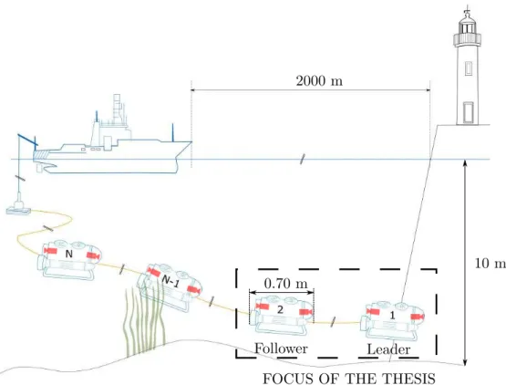
We choose to control the tether shape by adding several robots linked together all along it. We call this concept the chain of mini-ROVs (see Figure 1.9). The robots play the role of actuators and change the whole tether shape depending on the situation at hand. Our strategy is to avoid any contact with obstacles. If the depth is too narrow, it would be better to maintain the tether more taut in order to prevent it from dragging on the seabed. Otherwise, if the environment is more spacious, the tether can be more slack in order to give more freedom of motion to the robots.
The robots that compose the chain are compact, lightweight and with a limited sensory payload. Thus, we choose to investigate the use of the onboard camera to perceive and estimate a parameterized geometric model of the cable. The main focus of this thesis is to manage the tether linking two robots through visual feedback. These robots are named leader, for the front vehicle, and follower, for the rear vehicle. The thesis objective can be therefore summarized by the following question:
How can we manage a tether link between two successive robots, a leader and a follower, within the chain through visual sensory feed-back?
The proposed chain of mini-ROVs will operate under the set of assumptions listed below:
A.1.1 the maximum distance between robots is about 10 meters;
A.1.2 the robots can navigate at slightly different depths (difference less than 5 meters, depending on the tether length);
A.1.3 the roll and pitch motion of the robots are mechanically stabilized or regulated at low level to keep the vehicle horizontal;
Our Scientific Focus: Vision Servoing of a Pair of Robots in a Chain of Mini-ROVs31
A.1.4 the robots are equipped with a frontal and/or a rear camera that films the tether; A.1.5 each robot within the chain must manage the tether segment preceding it; A.1.6 the leader robot should not manage any portion of the tether, being free to explore
its surroundings and execute other tasks;
A.1.7 the leader robot may be outside the follower camera field of view, but a portion of the tether is always visible.
A.1.8 the tether is detectable in the camera image flow;
A.1.9 the tether linking both robots is negatively buoyant and the tether plane remains in the vertical. The tether lowest point is always situated between both robots;
10 m 0.70 m
Follower Leader
FOCUS OF THE THESIS 2000 m
Figure 1.9: A chain of N compact tethered robots used to explore shallow waters. The thesis focuses on the shape control of the tether link between the first two robots, namely the leader and its immediate follower. The robots that compose the chain are light-weight mini-ROVs equipped with a frontal and rear cameras and an IMU.
The maximum distance between the robots is limited because the modeling errors would be propagated over a too long length of tether and then affect our management strategy. A camera mounted on the front of the robot will be used to give real-time informations about the current tether shape. The camera is supposed to be near the tether attachment point on the robot so that at least a portion of the tether can be captured all along the mission. This also gives more freedom of motion to the leader robot that is not required to be in the field of view of the follower.
As depicted in Figure 1.10, the tether management strategy we proposed can be decomposed into three main steps. First, the tether is detected in the camera image. Secondly, the detected points are used to estimate a parametrized geometric model that fits the tether observed shape. Third, the current tether parameters are entered in a control loop that will displace the tether attachment points so that a desired shape of the tether is reached. Actually, the tether desired shape is obtained through the regulation of robots relative pose. Both robots could enter in the control loop, but we took the choice of leaving the leader robot free to move in the environment and execute other tasks. The follower robot, in turn, will be in charge of moving itself in order to regulate the tether shape. Each step mentioned above will be developed in the following three Chapters of this document, as presented in right side of Figure 1.10.
Chapter 2: system modeling
the tether and robot models are introduced detect the tether tether desired shape calculate variation of tether-shape features estimate the current shape of the tether move follower robot to reach desired shape Chapter 3 Chapter 4 START Chapter 3: tether perception
the proposed method for tether perception and shape
estimation is introduced
Chapter 4: tether shape control
the proposed method for tether shape control is
developed
Chapter 5: Conclusions
concluding remarks are given and work perspectives
are analyzed
Figure 1.10: Left: simplified algorithm chart flow of the proposed vision-based tether shape control scheme. Right: short presentation of the following Chapters content.
Chapter 2
System Modeling
This Chapter presents the model of the tether used and the robotic system composed of two underwater robots linked together by the tether, which is under study in this thesis. This set is the initial portion of the chain of tethered robots presented in the previous Chapter. The robots do not have the same task in this system: one is the leader, and has as main task the exploration of its surroundings; the other is the follower, behind the leader, whose main task is the control of the tether shape in order not to hamper the leader movements. The follower robot should manage the tether shape primarily using its own sensory feedback. In this thesis, the objective is to use the tether as it is, and not considering additional sensors that could equip the tether to obtain sensory feedback on its current shape. The Chapter is organized in three parts. The first part deals with the catenary equations, the second part presents the model of the robots and the last part gives the relation between the kinematics of the robots and the kinematics of the attachment points.
2.1
Tether Model
The underwater tether we use in this work is slightly negative buoyant, which is fre-quently the case of tethers and umbilicals that transfer power. They are used in main-tenance, survey (see Section 1.3.2) and archaeological missions (Khatib et al., 2016). We assume that our tether is a perfectly inextensible and flexible cable with a constant transversal section and constant linear density. From these assumptions, we choose to model the tether as a catenary.
2.1.1 Catenary Equation
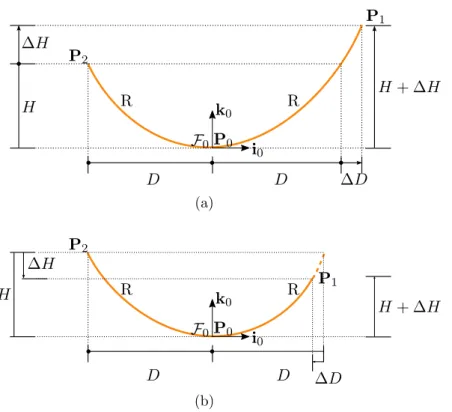
The catenary curve is the shape of a perfectly flexible, inextensible hanging cable that is subject to uniform load distribution along itself and that is supported at its extremities (Johnston et al., 2009).
Figure 2.1 presents a scheme of a hanging cable attached at points P1 and P2.
The cable lowest point, P0, is supposed to be at the center of the coordinate frame
![Figure 3.17: The initial guess function g(b) given by equation (3.68) for a catenary whose feature vector is [0.6, 0.6] T](https://thumb-eu.123doks.com/thumbv2/123doknet/14536750.724181/96.893.278.659.297.598/figure-initial-guess-function-equation-catenary-feature-vector.webp)
![Figure 3.23: The descent of the GN algorithm marked by black dots. The starting point is at s 0 = [0.5, 0.5] T and the solution is at s = [0.40, 0.45] T , marked by a red star.](https://thumb-eu.123doks.com/thumbv2/123doknet/14536750.724181/104.893.312.682.286.599/figure-descent-algorithm-marked-black-starting-solution-marked.webp)
