HAL Id: tel-00843874
https://tel.archives-ouvertes.fr/tel-00843874
Submitted on 12 Jul 2013HAL is a multi-disciplinary open access archive for the deposit and dissemination of sci-entific research documents, whether they are pub-lished or not. The documents may come from teaching and research institutions in France or abroad, or from public or private research centers.
L’archive ouverte pluridisciplinaire HAL, est destinée au dépôt et à la diffusion de documents scientifiques de niveau recherche, publiés ou non, émanant des établissements d’enseignement et de recherche français ou étrangers, des laboratoires publics ou privés.
scale systems
Russel Nzekwa
To cite this version:
Russel Nzekwa. Building manageable autonomic control loops for large scale systems. Software Engineering [cs.SE]. Université des Sciences et Technologie de Lille - Lille I, 2013. English. �tel-00843874�
D´epartement de formation doctorale en informatique Ecole doctorale SPI Lille´ UFR IEEA
Building Manageable Autonomic
Control Loops for Large Scale Systems
TH`
ESE
pr´esent´ee et soutenue publiquement le 05/7/2013
pour l’obtention du
Doctorat de l’universit´
e Lille 1 Sciences et Technologies
(sp´ecialit´e informatique)
par
Russel Nzekwa
Composition du jury
Rapporteurs : Jean-charles Fabre - Professeur des Universit´es, ENSEEIHT, Toulouse- France Sara Bouchenak - Maˆıtre de Conf´erences, Universit´e de Grenoble - France
Examinateurs : Jacques Malenfant - Professeur des Universit´es, Universit´e Pierre et Marie Curie - France Eric Rutten - Charg´e de Recherche, LIG/INRIA Grenoble - France
Directeurs : Lionel Seinturier - Professeur des Universit´es, Universit´e Lille I et IUF - France Romain Rouvoy - Maˆıtre de Conf´erences, Universit´e Lille I - France
A mes parents, Jacob et Paulette Nana pour leur soutient et leur amour inconditionnel
Remerciements
Cette thèse fut un parcours à la fois intellectuel et personnel. J’aimerai par conséquent saisir l’opportunité de ce moment qui sanctionne la fin de cette entreprise pour remercier tous ceux qui de près ou de loin ont contribué à rendre possible ce travail même s’ils ne sont pas nommément cités dans la suite.
En premier lieu, j’aimerai remercier mes encadrants Lionel et Romain. Lionel pour sa disponibilité et ses conseils bienveillants durant ces années. Romain, pour ses idées et son investissement constant. J’aimerai en deuxième lieu remercier les membres du jury Sara Bouchenak et Jean-Charles Fabre pour avoir accepté de rapporter ma thèse. J’adresse mes remerciements à Eric Rutten pour avoir accepté de participer au jury de ma thèse et à Jacques Malenfant pour avoir accepté de présider ce jury.
Je voudrai adresser mes vifs remerciements à tous les membres de l’équipe INRIA ADAM. En particulier à Laurence Duchien qui a toujours promu un esprit de fraternité au sein de l’équipe, et à Philippe Merle pour ses conseils sur les aspects du développement avec FraSCAti. Je tiens aussi à remercier mon collègue Daniel Romero avec qui nous avons beaucoup discuté et fait du jogging durant ces années.
Je voudrai aussi remercier les membres du projet SALTY avec qui j’ai collaboré durant ces années. En particulier, Filip Krikava avec qui j’ai échangé sur de nombreux aspects tech-niques dans le cadre du projet. J’aimerai aussi remercier les membres de l’équipe associée de l’université d’Oslo en particulier Frank Eliassen, pour l’accueil et l’accompagnement. Merci également aux différentes assistantes de l’équipe qui n’ont pas ménagé d’efforts pour nous accompagner dans la gestion de nos fiches de mission.
Je ne terminerai pas sans remercier mes amis qui m’ont soutenu et parfois inspiré durant cette période. Je pense en particulier à Mathieu, Jean et Rémi. Enfin mais pas des moindres, je voudrai remercier ma famille, en premier mes parents, Jacob et Paulette pour leur soutient inébranlable, mais aussi mes frères Joel, Michael, Gauis, Franklin et ma soeur Claudia pour le réconfort qu’ils m’ont apporté.
Abstract
Keywords: Autonomic systems, Feedback Control Loops, Stabilization, Service, Adaptation,
Com-ponent, Model driven engineering
Modern software systems are getting more complex. This is partly justified by the heterogeneity of technologies embedded to deliver services to the end client, the large-scale distribution of software pieces that intervene within a single application, or the requirements for adaptive software systems. In addition, the need for reducing the maintenance costs of software systems has led to the emer-gence of new paradigms to cope with the complexity of these software. Autonomic computing is a relatively new paradigm for building software systems which aims at reducing the maintenance cost of software by building autonomic software systems which are able to manage themselves with a minimal intervention of a human operator.
However, building autonomic software raises many scientific and technological challenges. For example, the lack of visibility of the control system architecture in autonomic systems makes them difficult to maintain. Similarly, the lack of verification tools is a limitation for building reliable au-tonomic systems. The flexible management of non-functional-properties, or the traceability between the design and the implementation are other challenges that need to be addressed for building flexi-ble autonomic systems.
The main contribution of this thesis is CORONA. CORONA is a framework which aims at help-ing software engineers for buildhelp-ing flexible autonomic systems. To achieve that goal, CORONA relies on an architectural description language which reifies the structure of the control system architec-ture. CORONA enables the flexible integration of non-functional-properties during the design of autonomic systems. It also provides tools for conflicts checking in autonomic systems architecture. Finally, the traceability between the design and the runtime implementation is carried out through the code generation of skeletons from architectural descriptions of control systems. These properties of the CORONA framework are exemplified through three case-studies.
Mots-clés: Applications autonomes, Boucle de contrôle rétroactive, Stabilisation, Service, Adaptation, Composant, Ingénierie dirigé par les modéles.
Les logiciels modernes sont de plus en plus complexes. Ceci est dû en partie à l’hétérogénéité des solutions misent en oeuvre, au caractère distribué des architectures de déploiement et à la dynamicité requise pour de tels logiciels qui devraient être capable de s’adapter en fonction des variations de leur contexte d’évolution. D’un autre coté, l’importance grandissante des contraintes de productivité dans le but de réduire les coûts de maintenance et de production des systèmes informatiques a favorisé l’émergence de nou-veaux paradigmes pour répondre à la complexité des logiciels modernes. L’informatique des systèmes autonomes (Autonomic computing) s’inscrit dans cette perspective. Elle se pro-pose entre autres de réduire le coût de maintenance des systèmes informatiques en dévelop-pant des logiciels dits autonomes, c’est à dire dotés de la capacité de s’auto-gérer moyennant une intervention limité d’un opérateur humain.
Toutefois, le développement de logiciels autonomes soulèvent de nombreux défis sci-entifiques et technologiques. Par exemple, l’absence de visibilité de la couche de contrôle dans les applications autonomes rend difficile leur maintenabilité, l’absence d’outils de véri-fication pour les architectures autonomes est un frein pour l’implémentation d’applications fiables, enfin, la gestion transparente des propriétés-non-fonctionnelles et la traçabilité en-tre le design et l’implémentation sont autant de défis que pose la construction de logiciels autonomes flexibles.
La principale contribution de cette thèse est CORONA. CORONA est un canevas logi-ciel qui vise à faciliter le développement de logilogi-ciels autonomes flexibles. Dans cet objectif,
CORONA s’appuie sur un langage de description architecturale qui réifie les éléments qui
forment la couche de contrôle dans les systèmes autonomes. CORONA permet l’intégration transparente des propriétés-non-fonctionnelles dans la description architecturale des sys-tèmes autonomes. il fournit aussi dans sa chaîne de compilation un ensemble d’outils qui permet d’effectuer des vérifications sur l’architecture des systèmes autonomes. Enfin, la traçabilité entre le design et l’implémentation est assurée par un mécanisme de génération des skeletons d’implémentation à partir d’une description architecturale. Les différentes propriétés de CORONA sont illustrées par trois cas d’utilisation.
Contents
List of Tables xv Chapter 1 Introduction 1 1.1 Introduction. . . 1 1.2 Problem Statement . . . 3 1.3 Dissertation Goals . . . 4 1.4 Contributions . . . 5 1.5 Dissertation Roadmap . . . 6 1.6 Publications . . . 7Part I State of the Art 9 Chapter 2 State of the Art 11 2.1 Autonomic Computing . . . 12
2.2 Existing Autonomic Systems Approaches. . . 16
2.3 Assessing Autonomic Systems . . . 26
Chapter 3 Salty Model 33
3.1 SALTY Structural Model . . . 34
3.2 SALTY Graphical Formalism . . . 37
3.3 SALTY DSL . . . 39
3.4 Summary . . . 42
Part II Contribution 43 Chapter 4 Contributions Overview 45 4.1 Challenges Revisited. . . 46
4.2 Goals Revisited . . . 47
4.3 CORONA in a Nutshell . . . 48
4.4 Summary . . . 51
Chapter 5 Runtime Architecture 53 5.1 Feedback Control Loops and Autonomic Systems . . . 54
5.2 Runtime Component-based Feedback Control Loops . . . 56
5.3 Feedback Control Loop Customization . . . 67
5.4 Summary . . . 79
Chapter 6 Compilation Infrastructure 81 6.1 Component-based Generative ToolChain . . . 82
6.2 Mapping from SALTY Model to SCA Model . . . 85
6.3 Control Loop Architecture Distribution . . . 89
6.4 Conflicts Checking on Feedback Control Loop Architectures. . . 93
6.5 Control Loop Architecture Evolution . . . 105
Part III Validation 109
Chapter 7 Condor Case-Study 111
7.1 Case-study Objective. . . 112
7.2 Condor Case-Study Description . . . 112
7.3 Control System Architecture . . . 113
7.4 Quantitative Evaluation . . . 115
7.5 Summary . . . 120
Chapter 8 Fire Emergency Case-Study 123 8.1 Case-Study Objective . . . 124
8.2 Scenario Description . . . 124
8.3 Control System Architecture . . . 125
8.4 Control System Implementation & Measures . . . 126
8.5 Summary . . . 130
Chapter 9 Smart-Mall Case-Study 131 9.1 Objective . . . 131
9.2 Smart-Mall Scenario Description . . . 132
9.3 Experiment & Measures . . . 134
9.4 Summary . . . 139
Part IV Conclusion & Persperctives 141 Chapter 10 Conclusion 143 10.1 Summary of the Dissertation . . . 143
10.2 Perspectives . . . 146
List of Figures
2.1 Structure of an Autonomic Element [Kep05]. . . 14
2.2 Overview of an Autonomic System Architecture . . . 15
2.3 Overview of the Jade Approach [BPHT06] . . . 17
2.4 Architecture of Unity Autonomic System . . . 19
2.5 Architecture of an Autonomic Agent in Autonomia . . . 20
2.6 Rainbow System Architecture with Customization Points [wC08] . . . 21
2.7 Ceylan Autonomic Control Architecture [MDL10] . . . 23
2.8 Control Architectural Style in DiaSpec . . . 24
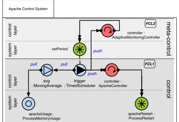
3.1 SALTY Graphical Notations . . . 38
3.2 Example of Apache Control Architecture Representation with the SALTY Specification . . . 38
3.3 Annotation Class Diagram . . . 41
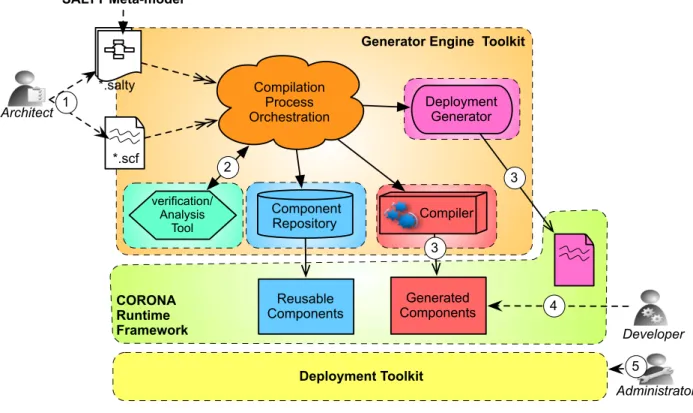
4.1 Overview Of the CORONA Development Process . . . 49
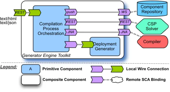
4.2 SCA Architecture of the CORONA Toolchain . . . 50
5.1 Close And Open Loop Paradigms . . . 55
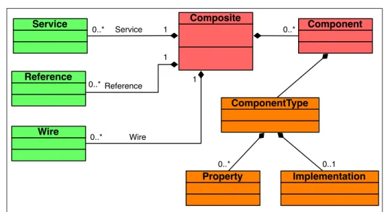
5.2 Basic concepts of the SCA Metamodel . . . 58
5.3 Graphical Representation of a Component in SCA . . . 58
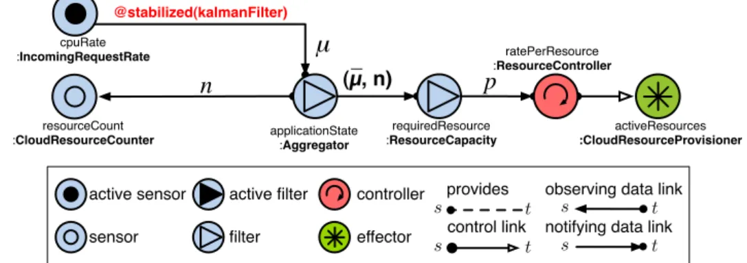
5.4 Auto-Scale Feedback Control Architecture. . . 59
5.6 Generated Sensors Artifacts . . . 62
5.7 Customizable MAPE-K Architecture Model . . . 68
5.8 Feedback Block Diagram in Control Engineering . . . 70
5.9 Unstable Auto-Scale Feedback Control System . . . 70
5.10 Classification of Stabilization Algorithms According to their Class and Cost . 76 5.11 Relationships between algorithms of the first(a), second (b) and third (c) layer of the classification . . . 77
5.12 Stabilization Algorithms Composition Models . . . 78
6.1 ToolChain Key Features Behavior . . . 83
6.2 SCA Architecture of the CORONA Compiler . . . 83
6.3 Condor [TTL05] Control Loop Architecture . . . 86
6.4 Illustration of Possible ambiguity in the interaction model . . . 88
6.5 Basic Concepts of the Network Meta-Model . . . 90
6.6 Illustration of a Feedback Control Loop Architecture with Constraints Anno-tations . . . 92
6.7 Computation Result of the location Optimizer Service . . . 93
6.8 Illustration of the Invisible Interference Problem . . . 94
6.9 Conflicts verification Process . . . 96
6.10 Direct overlaps Patterns . . . 97
6.11 Transitive overlap Example . . . 98
6.12 (A)– Control Architecture with Conflicts, (B)– Resolution of Architecture Con-flicts with Proxy Pattern . . . 102
6.13 (A)– Resolution of Conflicts with the Supervisor Mechanism, (B)– SCA imple-mentation of the Supervisor Mechanism on an Effector . . . 103
6.14 Supervisor Mechanism Coordination Logic . . . 104
6.15 Control Loop Architecture Evolution Cycle . . . 105
6.16 Control Architecture Selective Generation . . . 106
7.1 Self-Adaptive Distributed Infrastructure . . . 113
7.2 Self-Scale Feedback Loop. . . 114
7.4 Feedback Loops Overlaps Detection Time . . . 116
7.5 System without Feedback Loops . . . 118
7.6 System With a Single Budget Feedback Loop . . . 118
7.7 System With a Single User SLA Feedback loop . . . 119
7.8 System with Uncoordinated Feedback Loops . . . 119
7.9 coordinated Control System Architecture . . . 121
7.10 System with Coordinated Feedback Loops . . . 121
8.1 Illustration of the Fire-emergency Scenario . . . 125
8.2 Architecture of the fire-emergency Control System . . . 126
8.3 Fire-emergency SCA assembly architecture . . . 129
9.1 Smart-Mall Scenario illustration. . . 133
9.2 Showroom Control System Architecture . . . 135
9.3 Stabilized application behavior with Kalman Filter or Delta Operator . . . 136
9.4 Stabilized application behavior with Horizontal Composition (DO+KF) . . . 136
9.5 Media Player Control System Architecture . . . 137
9.6 Variation of Triggered Adaptations . . . 138
List of Tables
2.1 Classification of Architecture-based Autonomic Solutions. . . 29
5.1 Characterization of Stabilization Algorithms According to the Data Scope Cri-terion.. . . 74
5.2 Analytic Definition of Algorithmic Process Behavior Classes . . . 75
6.1 Mapping Rules Between SALTY and SCA Concepts . . . 88
Chapter
1
Introduction
“Civilization advances by extending the number of important operations which we can perform without thinking about them."-Alfred N. Whitehead Contents 1.1 Introduction . . . . 1 1.2 Problem Statement . . . . 3 1.3 Dissertation Goals . . . . 4 1.4 Contributions . . . . 5 1.5 Dissertation Roadmap . . . . 6 1.6 Publications . . . . 7
1.1
Introduction
Think in a wink about “computing systems capable of running themselves, adjusting to varying
circumstances, and preparing their resources to handle most efficiently the workloads we put upon them; capable to anticipate their needs and allow users to concentrate on what they want to accomplish rather than figuring how to rig the computing system to get them there" [IBM01]. It is in this terms that Paul Horn, senior vice president of IBM research, presented in 2001 his vision of the future of information systems. This new vision of software systems is the subject of the autonomic computing.
Autonomic computing is a nearly recent research field that addresses the increasing
com-plexity of software systems. Modern software applications are distributed, and are build from heterogeneous components. This make them very difficult to maintain. In particular, the growth of software complexity has blew up the cost of maintenance. Some estimate that, the number of IT workers required to support billions of users interacting with millions of
business applications connected via Internet is about 200 million, which is almost the popu-lation of a country like the United State of America. Recently in France, the 6th of July 2012, customers of a well-established telecommunication company have experienced a blackout due to a critical software failure. For several hours, customers have not been able to receive text messages or make phone calls. More than 200 engineers were mobilized to solve the fail-ure, and for hours could not figure where the problem was. The company estimated to 30 million euros, the cost related to that failure. Undoubtedly, the actual complexity of software infrastructures is a threat that could lead information technology to a serious crisis.
Up until recent years, the maintenance cost of software systems was not a matter of concerns. Indeed, the improvement of hardware performance has been the main focus of the research and the industry community over these last decades. In particular, the fulfillment of predictions of Moore’s law has allowed to develop faster and cheaper systems. In the same time, software development techniques were improving, and the emergence of object oriented languages in the early 90’s, and components oriented languages a bit later, have significantly increased the quality of software systems. However, the advent of Internet has given rise to a new class of software systems that are heterogeneous, large-scale, and distributed. The maintenance of this new class of systems is challenging at least for the three follow-ing reasons:
• Heterogeneity. The reduction of the time to market to cope with a competitive economic environment has forced software vendors to bet on the reuse of off-the-shelves compo-nents (COTS). That is, new software systems are build by assembling a set of existing software pieces developed by the vendor or his partners. Existing pieces of software are developed in various technologies. As a consequence, the maintenance of a soft-ware solution based on several technologies is very challenging for a human adminis-trator.
• Dynamicity. Modern software systems evolve in a dynamic environment where re-sources they operate on are subject to constant changes. A change can be the availabil-ity or the unavailabilavailabil-ity of some services, or a workload surge in the demand of one service. Therefore, software systems need to be adapted constantly according to varia-tions in their environment in order to achieve their objectives. When this dynamicity is coupled with scalability, it becomes very challenging for a human operator to manage them.
• Scalability. Software systems are distributed at large-scale, and consist of many inter-connected components that collaborate in order to deliver the expected service. A global coordination of these components is challenging and error-prone.
Autonomic computing is a good candidate for addressing these challenges, because it enables software systems to manage themselves without or with a limited human interven-tion. Autonomic systems shift the burden of managing software systems from the human to
1.2. Problem Statement
the system itself. The benefits of autonomic computing for the IT industry are multiple. For example, the reduction of the maintenance costs of software systems, the reduction of system failure due to human errors, or the optimization of resources usage. However, engineering such systems is a scientific and technological challenge.
Important progress has been made by the research and the industry community for de-veloping autonomic solutions. Notably, the adoption of service oriented architecture(SOA) in order to cut down the complexity of engineering autonomic systems. SOA advocates a loose-coupling between components of a software system in order to manage the later ef-ficiently. In addition, the increasingly automatization of administrative tasks in autonomic software solutions has reduced the workload for the human operator. Many autonomic systems provide high-level abstractions for hiding the complexity of the managed system. These abstractions enable developers of autonomic systems to express the behavior policies of autonomic systems without worrying about the complexity of the managed system.
Despite these progresses, engineering autonomic systems rise many difficulties. A prominent difficulty is the complexity of maintaining autonomic systems or making them evolve. That is because in traditional engineering approaches, the architecture of autonomic managers is masked under layers of abstractions. As a consequence, it is very difficult to understand the behavior of autonomic managers. This lack of visibility is a limitation for engineering large-scale autonomic systems where multiple autonomic managers collaborate together in order to adapt according to changes in their environment. In particular, the burden of detecting and preventing conflicts in the control architecture fall on developers’ shoulders. This results in error-prone and time-consuming tasks for them.
This thesis takes a step ahead concerning the engineering of autonomic systems. We pro-pose a new brand approach for engineering autonomic systems. Our approach propro-poses to reduce the time and efforts required for implementing autonomic systems. For that purpose, we rely on generative techniques of the code source and automated verifications tools for ensuring the validity of the control system architecture. Our approach fosters the visibility of the control system architecture and enables the implementation of amenable autonomic solutions.
Structure of the chapter
The rest of this chapter is organized as follows: In Section1.2, we identify the motivation of this dissertation. Then, in Section1.3, we introduce the goals of this dissertation. We give a glimpse of the contribution of this thesis in Section1.4. Section1.5presents the structure of this document by reviewing main ideas of each chapter. Finally, we conclude this chapter with a list of publications (cf. Section1.6).
1.2
Problem Statement
In the previous section, we have presented autonomic computing as a good candidate for tack-ling the growing complexity of software systems, in particular in a large-scale environment.
However, despite notable advances, many problems hinder the engineering of amenable au-tonomic systems. In this dissertation, we have identified some of them that we discuss in this section.
Visibility of the control system
Existing autonomic software solutions lack of visibility of the control system. In order to im-plement amenable autonomic systems, feedback control loops that govern self-adaptation must be visible at design and at runtime. This visibility increases the understanding of con-trol flows, and enables a transparent coordination of feedback loops that implement various behavior. The visibility of the control system architecture is one of the problem towards amenable autonomic solutions. For many existing autonomic solutions, the control system architecture remains hidden at runtime.
Traceability from the control design to the runtime implementation
Traceability is a strong asset for having amenable autonomic solutions. In fact, very often the design and the implementation of the control system are not traceable. That is, it does not exist a strong coherence between the design and the implementation. That is because devel-opers are not guided during the implementation of autonomic systems. As a consequence, developers implement control behavior in a adhoc manner. Traceability is important for supporting a flexible evolution of the control architecture.
Lack of tools and algorithms for verification
Large-scale autonomic systems, very often involve many control systems that collaborate to achieve conflictual objectives. The detection of this conflicts are crucial to ensure the consistency of the control system. In addition, the development of algorithms in order to check this conflict reduce the cost of engineering autonomic systems. The lack of visibility of the control architecture does not enable the implementation of tools and algorithms for verification in many existing autonomic solutions.
Transparent support of Non-Functional-Properties (NFP)
Autonomic solutions implement NFPs to customize the manner in which their functionali-ties are delivered. Many existing autonomic solutions does not provide support for imple-menting NFPs in a transparent manner, usually they are indistinguishably embedded in the control logic behavior. We think that in order to leverage a flexible adaptation of autonomic systems, NFPs must be transparently implemented in the control system.
1.3
Dissertation Goals
Our objective in this dissertation is to provide a solution for engineering amenable auto-nomic softwares. In the section above (cf. Section1.2), we have highlighted some problems that hinder the achievement of that objective. In order to address these problems, we pro-pose a generic approach for engineering autonomic solutions where feedback control loops are reified as first-class citizens. We leverage the visibility of feedback loops by providing a control-oriented language for designing control systems. We address the traceability from
1.4. Contributions
the design to the implementation of the control architecture by ensuring a strong mapping between design and runtime concepts. The visibility of the control system enables to develop algorithms for automatic checking of the control architecture. Finally, we provide a flexible support for the implementation of non-functional-properties in the control architecture. The main goals of our proposal are the following:
• Domain agnosticism. We aim at defining a generic solution which targets several application domains. Agnosticism with regards to the domain of application enables our solution to be used for a wide range of autonomic systems. The design of the control architecture must be independent of a specific implementation platform. • Flexible adaptation and evolution. To reduce the complexity of maintaining
auto-nomic systems, feedback loops that govern adaptations must become visible at run-time. The visibility of control flows in the control system facilitates the engineering of scalable adaptive systems where several control systems collaborate in order to achieve complex objectives. In addition, it facilitates the evolution of the control system archi-tecture.
• Cost-effectiveness. It is important to develop a solution that is cost-effective for en-gineering autonomic systems. The cost of enen-gineering autonomic system can be ad-dressed at two different levels: At the implementation level, by providing an imple-mentation support for developers of autonomic systems; at the design level by sup-porting automatic verification of the control architecture.
• Consistency. The consistency of the control system architecture is a good property for building reliable autonomic systems. It is important to detect potential conflicts in the control system architecture before the deployment. This will save a lot of time and efforts for developers of autonomic systems.
1.4
Contributions
In order to enhance the understanding of this dissertation, we briefly describe in this section the main contribution of this thesis. The contribution of this dissertation can be organized in the four following points:
• The first contribution is the reification of feedback control loops as first-class citizen at runtime. This is done by ensuring a strong mapping between architectural concepts and implementation concepts. We leverage the visibility of feedback control loops by relying on a service component platform.
• The second contribution consists of enabling the customization of the MAPE-K archi-tecture pattern of feedback control loops. In particular, we focus on the integration of stabilization algorithms for designing stable control systems.
• The third contribution is the traceability. we provide an automated mapping between the control architecture design and its runtime implementation. The implementation of the control architecture is guided in order to ensure the conformity between the design and the implementation.
• The fourth contribution is the support for verification when building autonomic sys-tems. We have identified and characterized conflicts patterns that can appears during control systems design, and have implemented tools for their detection and the auto-matic resolution of some them.
1.5
Dissertation Roadmap
This dissertation is divided in four parts. The first part gives an overview of the state-of-the-art of autonomic solutions, and introduces the SALTY1meta-model which is used in this dissertation for explaining our contribution. The second part is the Contribution part. This part explains the proposal of this dissertation. The third part of this thesis is the Validation
part. The Validation part presents some experimental evaluations that validate the proposal
of this dissertation. The Conclusion part is the fourth part of this dissertation. It provides a summary of this work, and discusses some perspectives.
Part I: State of the Art
• Chapter 2: State of the Art. In chapter 2, we introduce some backgrounds and defini-tions related to autonomic systems. Then, we give an overview of architecture-based autonomic solutions, classify them, and point out some limitations of these solutions. • Chapter 3: SALTY Model. This chapter presents the SALTY meta-model. In chapter
3, we first introduce the graphical formalism for designing a control architecture with the SALTY meta-model.
Part II: Contribution
• Chapter 4: Contributions Overview. This chapter revisits the challenges and the ob-jectives of this dissertation. Then, an overview of the our contribution called CORONA is introduced.
• Chapter 5: Runtime Architecture. This chapter presents two contributions of this dis-sertation. The first contribution consists of reifying feedback control loops as first-class citizen at runtime. The second contribution depicted in this chapter is the support for non-functional-properties through the customization of the control loop architecture.
1.6. Publications
• Chapter 6: Compilation Infrastructure. This chapter discusses the CORONA toolchain that provides support for engineering cost-effective autonomic system. It covers two other contributions of this dissertation. The first one is the traceability between the design and the implementation of control system, and the second one is the verification algorithms for conflict checking in the control architecture.
Part III: Validation
• Chapter 7: Condor Case-Study. This chapter validates one of the claim of this thesis which is the consistency of the control architecture. It shows how verifications algo-rithms can be used for designing more reliable autonomic systems. This is illustrated on the Condor case-study.
• Chapter 8: Fire Emergency Case-Study. This chapter validates the second claim of this dissertation which is integration & transparency. In particular, we discuss how control systems developed with CORONA can be integrated in existing control architecture. The integration & transparency claim is illustrated with the Fire emergency case-study. • Chapter 9: Smart Mall Case-Study. This chapter validates the integration of
stabiliza-tion algorithms in order to design flexible control systems
Part IV: Conclusion
• Chapter 10: Conclusion. This chapter gives a summary of this dissertation and recall the contributions of our proposal. We conclude this dissertation with a discussion of the perspectives of our work. We point out interesting research directions that could be addressed to complete and improve this thesis.
1.6
Publications
Below, we present the list of research articles that were published during this thesis. International Journals
• The DigiHome Service-Oriented Platform. Daniel Romero, Gabriel Hermosillo, Amirho-sein Taherkordi, Russel Nzekwa, Romain Rouvoy and Frank Eliassen. Software: Prac-tice and Experience (SPE). 2011. Rank(CORE): A. To appear.
• RESTful Integration of Heterogeneous Devices in Pervasive Environments. Daniel Romero, Gabriel Hermosillo, Amirhosein Taherkordi, Russel Nzekwa, Romain Rouvoy and Frank Eliassen. In 10th IFIP International Conference on Distributed Applications and Interoperable Systems (DAIS’10). pages 113–126 of LNCS 6115 (Springer). Amster-dam, Netherlands. June 2010.
International Workshops
• Modelling Feedback Control Loops for Self-Adaptive Systems. Russel Nzekwa, Romain Rou-voy, Lionel Seinturier. 3rd International DisCoTec Workshop on Context-Aware Adap-tation Mechanisms for Pervasive and Ubiquitous Services (CAMPUS 2010). Amster-dam, Netherlands. June 2010.
• A Flexible Context Stabilization Approach for Self-Adaptive Application. Russel Nzekwa, Romain Rouvoy, Lionel Seinturier. 7th IEEE Workshop on Context Modeling and Rea-soning (CoMoRea) at the 8th IEEE International Conference on Pervasive Computing and Communication (PerCom’10). Manheim, Germany. March 2010.
• Towards a Stable Decision-Making Middleware for Very-Large-Scale Self-Adaptive Systems. Russel Nzekwa, Romain Rouvoy, Lionel Seinturier. The 8th BElgian-NEtherlands soft-ware eVOLution seminar (BENEVOL’09). Louvain-la-Neuve, Belgium. December 2009.
Part I
Chapter
2
State of the Art
"Nothing in the world is more dangerous than sincere ignorance and conscientious stupidity."
–Martin Luther King
Contents
2.1 Autonomic Computing . . . . 12
2.1.1 Context . . . 12
2.1.2 Definitions & Taxonomy . . . 12
2.1.3 Autonomic System Properties . . . 15
2.2 Existing Autonomic Systems Approaches . . . . 16
2.2.1 JADE . . . 16 2.2.2 TUNe . . . 18 2.2.3 UNITY . . . 18 2.2.4 AUTONOMIA. . . 20 2.2.5 RAINBOW . . . 21 2.2.6 CEYLON . . . 22 2.2.7 DiaSpec . . . 24
2.3 Assessing Autonomic Systems . . . . 26
2.3.1 Comparison Criteria . . . 26
2.3.2 Classification of Autonomic System Approaches . . . 27
2.4 Summary . . . . 30
In this chapter, we introduce some basics concepts and software approaches used as a background for this dissertation, we also present the scientific context and rationales of this thesis. In particular, we define concepts related to autonomic computing and review existent software solutions for building autonomic systems.
Structure of the Chapter
This chapter is organized as follows: Section 2.1defines and introduces some concepts re-lated to autonomic computing. Section2.2presents existing software approaches for build-ing autonomic systems. In Section2.3, we discuss the limitations of these approaches and point out challenges ahead in order to address them. Finally, we conclude (cf. Section2.4) this chapter with a summary.
2.1
Autonomic Computing
In this section, we start by introducing the context of autonomic computing (cf. Sec-tion 2.1.1), then we give some definitions and explain some concepts related to the auto-nomic computing (cf. Section2.1.2). We end this section by presenting some properties of an autonomic control system (cf. Section2.1.3).
2.1.1 Context
In the previous chapter (cf. Chapter 1), we have stated that the increasing complexity of software systems, and their maintenance costs were the prominent motivations for auto-nomic computing. Autoauto-nomic computing draws upon a wide range of research fields, from biology to robotic through control engineering [Kep05]. This makes difficult any attempt for characterizing and describing this research field.
The term autonomic in autonomic computing, comes from the analogy with the au-tonomous nervous systems that ensures the regulation of visceral functions of the human body like, the respiration, the digestion or the micturition. The nature provides plenty of il-lustrations of complex autonomic systems that cooperate in an astonishing manner in order to achieve the desired goal. Despite the complexity of biological autonomic systems, they appear to be more tolerant to failure than software systems. One of the purpose of autonomic
computing is to identify and understand principles behind the self-adaptive behavior of
nat-ural autonomic systems, in order to implement software systems with similar properties. In contrast to biological autonomous systems where control loops that govern self-adaptation are often not visible, feedback loops are the central element of control engineer-ing. Control engineers are provided with well established models, tools and techniques for designing and characterizing control systems [DB00]. Autonomic computing researchers seek to which extent some principles of control theory can be used for reasoning about autonomic software systems.
2.1.2 Definitions & Taxonomy
There are more than one definition of what is autonomic computing in the literature. We have retained here three of them, proposed by renowned scientists of this research field:
2.1. Autonomic Computing
Definition 1: “The vision of autonomic computing is to create software through self-* prop-erties" [SH05].
Definition 2: “Autonomic computing is the ability to manage your computing enterprise through hardware and software that automatically and dynamically responds to the requirements of your business" [Mur04].
Definition 3: “Systems manage themselves according to an administrator’s goals. New components integrate as effortlessly as a new cell establishes itself in the human body" [Kep05].
The above three definitions are coherent, and underline the ultimate purpose of au-tonomic computing, which is to reduce the complexity of implementing and maintaining information systems for software engineers.
Autonomic computing vision for addressing the complexity of software systems premises
on the IBM blueprint [IBM01]. According to the IBM’s vision, autonomic systems must be a collection of interacting autonomic elements. Autonomic elements are the individual con-stituents of the system that deliver a given service to humans or other autonomic elements.
Autonomic elements must manage their relationships with their environment (managed
sys-tem or other autonomic elements) in accordance with established policies of the autonomic system. Consequently, they will relieve humans from the responsibility of directly intervene for adjusting the behavior of the managed system. The IBM’s vision of autonomic systems is modeled into the MAPE-K paradigm.
Figure2.1depicts the structure an autonomic element. The autonomic element implements the MAPE-K paradigm. MAPE-K stands for Monitor, Analyze, Plan, Execute and Knowledge. The MAPE-K paradigm defines the essentials activities of an autonomic element.
Monitor. The feedback cycle of an autonomic element starts with the monitoring activity. This activity consists of collecting information from the environment of the autonomic element that reflect changes of the monitored system. The monitoring activity is im-plemented by sensors.
Analyze. An autonomic element analyzes collected data from the previous activity (mon-itoring). The activity analyze is a part of the reasoning or decision-making of the au-tonomic element and aims at identifying symptoms that require the system to take specific actions.
Plan. The plan activity collects information from the activity analyze and makes decision about how the monitored system need to be adapt in order to reach the desirable state. Execute. To implement the decision taken, the autonomic element interacts with the
Autonomic manager
Knowledge
Managed element Analyze Plan
Monitor Execute
Figure 2.1: Structure of an Autonomic Element [Kep05]
Knowledge in the MAPE-K paradigm does not correspond to an activity of the autonomic
element. It expresses the base of information (control flow) that is exchanged between the four activities of an autonomic element. Autonomic elements are also known as autonomic
managers because they regulate the behavior of the system that they control by interacting
with the later. In the IBM vision of autonomic computing, an autonomic system arises from the interactions of autonomic managers amongst themselves (the coordination), and their interactions with the managed system. Autonomic elements of an autonomic system form the control system. An autonomic manager can be designed for achieving one or several goals. The term feedback control loop (FCL) usually refers to a control flow of the autonomic manager that implement a single goal. The control flow denotes the sequence of actions corresponding to activities of an autonomic manager.
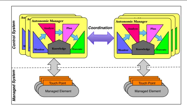
Figure 2.2depicts an autonomic system architecture. It generally consists of two sub-systems: the control system that implements the control behavior, and the managed system that consists of managed elements interacting with the control system. The control system consists of autonomic managers that cooperate in order to ensure a consistent behavior of the autonomic system. The type of coordination between autonomic managers can be of various forms [ASHP+08], hierarchical, peer-to-peer, hybrid. Interactions between autonomic managers and managed elements take place through touch-points.
2.1. Autonomic Computing Autonomic Manager Execute Analyze Plan Monitor Knowledge Autonomic Manager Execute Analyze Plan Monitor Knowledge Autonomic Manager Execute Analyze Plan Monitor Knowledge Autonomic Manager Execute Analyze Plan Monitor Knowledge Autonomic Manager Execute Analyze Plan Monitor Knowledge Autonomic Manager Execute Analyze Plan Monitor Knowledge Touch Point Managed Element Touch Point Managed Element Touch Point Managed Element Touch Point Managed Element Touch Point Managed Element Touch Point Managed Element Coordination C o n tr o l Sy s te m Ma n a g e d Sy s te m
Figure 2.2: Overview of an Autonomic System Architecture
In this section, we have introduced some definitions and concepts related to autonomic computing. We have also depicted the structure of an autonomic element with respect to the MAPE-K paradigm promoted by IBM. Autonomic systems adapt their behaviors according to changes in their environment in order to conform to their goals. Consequently, adaptation is a central aspect for autonomic systems. These adaptations can be of many kinds. In the next section, we introduce some properties of autonomic systems from the adaptation point of view.
2.1.3 Autonomic System Properties
Autonomic systems are characterized by four properties that defined their behavior. These properties were defined in accordance to self-adaptation mechanisms in biological organ-isms [KC03]. An autonomic system that implements all these four properties is qualified as
self-managed system. The following list elaborates in details on the properties of autonomic
systems.
• Self-configuration. This property refers to the capability of an autonomic system for dynamic reconfiguration in response to changes in the environment by installing, up-dating, or integrating new software entities.
• Self-healing. This property is also know as self-repair. It refers to the capability of an autonomic system to discover, diagnose, and react to disruptions. This property en-capsulates proactive actions of the system for preventing errors, faults or failures.
• Self-optimization. This property is also known as self-tuning. It characterizes the capabil-ity of the system for managing performance and resource allocation in order to satisfy its goals.
• Self-protecting. This property refers to the capability of the system for detecting failures and recover from them. Self-protecting autonomic systems defend their-selves against malicious attacks and mitigate their effects on the system behavior.
The above properties are usually subsumed under the term of CHOP (Configure, Heal, Optimize, and Protect) [HS06] or self-*. Now that we have introduced the architecture and properties of autonomic systems, let us look in details into some existing autonomic solu-tions.
2.2
Existing Autonomic Systems Approaches
As we mentioned at the beginning of this chapter, autonomic computing embraces a wide range of research fields, and makes it difficult to provide an exhaustive vision of the state-of-the-art. In this section, we present existing approaches for building autonomic systems. However, we are going to focus the spectrum of our analysis to architecture-based approaches which present a great interest for the rest of this dissertation.
Architecture-based approaches define for a class of systems, a vocabulary of element types,
properties common to the element types in theses systems, a set of constraints on the permitted composition, and the associated analyses for reasoning about this class of sys-tems [AAG93]. This means that architecture-based approaches provide a higher level abstrac-tion for reasoning or implementing soluabstrac-tions for a given domain.
2.2.1 JADE
Jade [BPHT06] is a framework for the management of distributed autonomic systems. Jade focus on the management of J2EE cluster legacy applications. Jade relies on the FRAC-TAL [BCS02] component model. The FRACTAL component model is a generic model for implementing complex software systems that can be dynamically adapted.
The autonomic behavior is achieved through autonomic managers that are in charge of regulating the behavior of the managed system. Figure2.3 gives an overview of the Jade approach. The implementation of the control system and the interaction with the managed system is done as follows:
• Interaction with the Managed System
Since managed applications are heterogeneous, developers must implement wrappers as FRACTAL components in order to provide uniform interfaces to interact with the control system. That is, the legacy system layer (clustered applications) is wrapped into a management layer implemented by FRACTAL components.
2.2. Existing Autonomic Systems Approaches !"#!$% &'()&($%&'()&($% !"#!$% &'()&($% !"#!$% *"+&,% -.)!("% /&#&0"% 1".23%"'$4"%5 /&#&0"% &'()&($% &'()&($% !"#!$% !"#!$% &'()&($% !"#!$% *"!,6" 1".23$+(,/,6&(,$# /&#&0"% 7&8" 1$2(9&%" :#!(&..&(,$# !"%4,'" ;&#&0"8<!5!("/
Figure 2.3: Overview of the Jade Approach [BPHT06]
• Implementation of the Autonomic Control Loop
Autonomic managers in the Jade approach are organized according to self-properties aspects like self-optimization or self-healing. Autonomic managers are implemented ac-cording to the MAPE-K paradigm. Jade provides flexible mechanisms for creating autonomic managers and to manage their deployment. The logic behavior of an auto-nomic manager is implemented in the decision block of the autoauto-nomic manager. It can be for example, an algorithm for resizing the cluster of replicated servers upon load surges for a self-optimization autonomic manager.
In the Jade approach, the implementation of autonomic managers conforms to the MAPE-K model. However, the separation of autonomic managers according to self-properties aspects is not always possible, because sometimes self-adaptive behaviors over-lap, and cannot be represented independently. In this case, it is almost impossible to im-plement them independently without creating conflicts. In addition, in the Jade approach, the coordination between autonomic managers is not explicit. Finally, Jade uses a generic syntax language (FRACTAL component syntax) for describing and implementing the archi-tecture of the control system. As a result, the visibility of the control system is hidden at runtime because it is hard to distinguish between control architecture components and man-aged system components. This lack of visibility is a threat for the autonomic system, because it does not allow verifications of the control system architecture in order to detect potentials conflicts between autonomic managers.
2.2.2 TUNe
Tune [BHS+08] is a platform designed for building autonomic managers. Tune is an exten-sion of the Jade framework. As Jade, Tune focuses on the autonomic management of legacy systems. Tune introduces an higher-level formalism for the specification of the deployment and the management policies of legacy J2EE systems. The purpose of the higher-level for-malism is to hide details of the FRACTAL component model, and provide a more intuitive syntax for wrapping these systems into a uniform abstraction interface, than what was avail-able in Jade.
The implementation of the control system and the interaction with the managed system is done as following:
• Interaction with the Managed System
In Tune, interactions with the managed system are implemented through the WDL lan-guage. This language enables developers to specified a list of methods with parameters, that can be called for a given wrapper component. At this stage the notion of sensor and
effector is not explicit.
• Implementation of the Autonomic Control Loop
The implementation of the control behavior is basically done through the reconfigu-ration language where developers specify reconfigureconfigu-ration policies for an autonomic manager. However, like for Jade, it is not clear how the control logic of an autonomic manager can be changed or specified.
Overall, Tune provides a higher level formalism to facilitate the implementation of au-tonomic managers for legacy J2EE servers. However, the introduction of a supplementary layer of abstraction masks the visibility of the control system architecture. This lack of visi-bility is a threat for implementing consistent control systems.
2.2.3 UNITY
Unity [CSW04] is one the first autonomic software solution that was implemented. Unity was developed by IBM which is a pioneer company in the development of software solutions that enable to build effective autonomic systems. Concurrently to the Unity project, IBM has developed other projects like ABLE [BSP+02] or the Autonomic Toolkit [Bar04] that rely on the multi-agent paradigm for implementing autonomic behavior.
Unity was designed for managing resource allocation in a distributed system [TCW+04]. The Unity project relies on the MAPE-K paradigm. Figure2.4illustrates the architecture of the Unity autonomic system. The Figure shows that the architecture of Unity autonomic system consist of autonomic applications, a resource pool, an arbiter, and a policy repository.
The implementation of the control system and the interaction with the managed system is realized as following:
2.2. Existing Autonomic Systems Approaches
Process
Resource Resource Resource
Resource pool policy repository
Autonomic
Application 1 Application kAutonomic
Arbiter
....
Figure 2.4: Architecture of Unity Autonomic System
• Interaction with the Managed System
The managed system in Unity is represented by the resource pool. Autonomic applications interact through managers directly with the resource pool. Mangers are able to increase or decrease resource allocation for a given application according to its needs. The com-munication between autonomic applications and the resource pool is completely specified and hard-coded through Java interfaces. The notions of sensor and effector remain very implicit.
• Implementation of the Autonomic Control Loop
The implementation of the control system is realized at the level of each application through a manager. The logic behavior of a manager is specified through a high-level policy language. All policies defined in the Unity environment are referenced in the
policy repository. The resource Arbiter is used in order to coordinate the access of auto-nomic applications to the resource pool.
Unity provides a very specialized and flexible solution for building autonomic systems. It focuses on the issue of resource allocation. Unity allows developers to specify control policies with an high level syntax. However, the specialization of Unity makes difficult its reuse for other type of autonomic management not related to the resource allocation. In ad-dition, the use of an arbiter for the coordination of autonomic applications limits the scalability of Unity. Finally, although the MAPE-K paradigm is used in Unity, the architecture of the control system remains fuzzy because its constituents are not clearly identified. For example,
the notions of sensor and effector of the MAPE-K paradigm cannot be explicitly infered from interfaces implementing the communication between the managed and the control system.
2.2.4 AUTONOMIA
The Autonomia [XSL+03][YCHP05] project was developed at the University of Arizona.
Au-tonomia defines an approach for building autonomic systems on the basis of multi-agents.
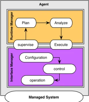
The purpose of the project is to provide developers of autonomic systems with tools for implementing mobile autonomous agents. Autonomia focus on increasing capacities of exist-ing software applications with “agent properties". Figure2.5 depicts the architecture of an autonomic agent in autonomia.
Execute Analyze supervise Managed System Configuration control operation Plan R u n ti m e Ma n a g e r In te rfa c e Ma n a g e r Agent
Figure 2.5: Architecture of an Autonomic Agent in Autonomia
Figure2.5shows that the architecture of an autonomic agent consists of two layers: the interface manager and the runtime manager. These layers implement the autonomic behav-ior of an agent in autonomia. In autonomia, the implementation of the control system and the interaction with the managed system is realized as follows:
• Interaction with the Managed System
Interactions with the managed systems are organized through the interface manager. It defines a set of operations that can be performed on the managed systems. These operations can be supervised by controllers which can be configured for executing au-tonomic tasks. The main constituents of the interface manager are depicted on Figure2.5.
2.2. Existing Autonomic Systems Approaches
• Implementation of the Autonomic Control Loop
The implementation of the control behavior within an agent is realized by the runtime
manager. The runtime manager defines the management policy of the autonomic agent.
These policies are expressed in the form of event-condition-action rules. As depicted on Figure2.5, the architecture of the runtime manager conforms the MAPE-K paradigm.
The whole approach adopted in Autonomia for implementing autonomic systems is very close to the one promoted by ORACLE with the JMX [ORA] framework in Java. JMX offers the possibility to enhance Java applications with management capabilities through the extension of JMX’s interfaces by Java classes. The architecture of the Autonomia framework is highly distributed and bring a lot of flexibility for defining policies of an autonomic agent. However, the definition of these policies are not coordinated for all autonomic agents of the environment. This can lead to some inconsistencies of the control system architecture. Finally, the language for implementing the control system does not reify its architecture.
2.2.5 RAINBOW
Rainbow [wC08][wCcHG+04] is a framework for implementing autonomic systems devel-oped at Carnegie Mellon University in 2004. The main claim of Rainbow is to reduce the cost of implementing autonomic systems. For that purpose, Rainbow defines a generic architec-ture of an autonomic system based on the MAPE-K paradigm that developers can customize to their needs. Rainbow supports a high-level description language for implementing the be-havior of the control system. Figure2.6 depicts the architecture of the Rainbow autonomic system.
Figure 2.6 shows that the Rainbow architecture conforms to the MAPE-K paradigm. The customization of the Rainbow architecture is represented by colored pentagons on Fig-ure2.6. In Rainbow, the implementation of the control system and the interaction with the managed system is realized as follows:
• Interaction with the Managed System
Rainbow requires a model of the managed system for reasoning about changes in the system. The translation infrastructure plays the role of mapping between the model of the managed system and its implementation. The translation infrastructure interacts with the managed system through effectors and probes. It forwards the informations collected from the managed system to the autonomic control system.
• Implementation of the Autonomic Control Loop
The implementation of the control system in Rainbow requires to define the model of the managed system in addition to the control architecture model. The constituents of the control architecture exist in a generic form, but must be customized for implement-ing specific behavior of a given application. The description of the autonomic manager in Rainbow is independent of the execution platform.
Rainbow offers an effective way to reduce implementation efforts when building auto-nomic systems. However, the main limitation of the Rainbow approach as pointed by the authors [wC08] is the centralization of the control system which can be an issue for the scal-ability of the solution.
2.2.6 CEYLON
Ceylon [MDL10] is a service oriented framework for building autonomic managers. Ceylon implements autonomic managers like an opportunistic composition of service oriented com-ponents. In Ceylon, complex management policies are achieved through the orchestration of simple policies implemented by specialized components. Figure2.7depicts the architecture of Ceylon autonomic system.
Figure2.7shows that the behavior of the control system is the result of the composition of service components by the task manager. The composition is opportunistic in the sense that, it is performed at runtime depending on the high level goals of the system. The imple-mentation of the control system and the interaction with the managed system is realized as follows:
• Interaction with the Managed System
Interactions with the managed system are implemented by individual service compo-nents. Components are activated or stopped by the task manager which is in charge of coordinating the behavior of individual components in order to achieved the goal
2.2. Existing Autonomic Systems Approaches
Figure 2.7: Ceylan Autonomic Control Architecture [MDL10]
of the control system. Ceylon relies on OSGI/iPOJO components model for the imple-mentation behavior of service components. The communication layer between service components and the managed system is not explicit for developers, neither the im-plementation of these components. In the Ceylon approach, service components are provided by the platform and registered in a repository as shown on Figure2.7. • Implementation of the Autonomic Control Loop
As depicted in Figure2.7, the control system in Ceylon is implemented by two entities: the strategy manager and the task manager. The strategy manager supervises the task manager. The task manager orchestrates the behavior of service components, by acti-vating and deactiacti-vating them when necessary. The behavior of the control system is configured through interfaces of the Ceylon container.The Ceylon container provides high level syntax for customizing different aspects of the control behavior like goal management, life-cycle management or human-machine interactions.
The strength of Ceylon is the service oriented component (SoC) approach for implement-ing autonomic systems. SoC offers an effective way to address the scalability of autonomic systems. In addition, Ceylon provides a high level syntax for specifying the behavior of the control system. However, the visibility of the control system architecture is masked by mul-tiple layers of abstractions. In particular, interactions between service components and the managed system, as well as their implementation logic are not transparent for developers. This is a critical threat for the control system because, it is a potential source of conflicts. The task manager tries to limit conflicts by ensuring that components with similar behavior are
not activated at the same time. However, since the architecture of the later is not explicit, the consistency of their coordination cannot be guaranteed.
2.2.7 DiaSpec
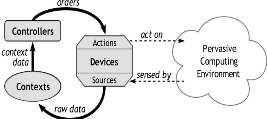
DiaSpec [CBCL11] is a domain specific architectural framework dedicated for the implemen-tation of autonomic applications. DiaSpec promotes the SCC (sense-compute-control) pattern. The SCC pattern presents a great similarity with the MAPE-K pattern. From an architec-tural perspective, in the SCC paradigm, we distinguish four types of elements: (1) sensors at the bottom of the architecture collect information from the environment; then (2) context
operators which processed this information; then (3) control operators, which refine this
infor-mation; and finally actuators at the top of the architecture which impact the environment. The Architectural style of the DiaSpec framework is depicted in Figure2.8.
!"#$%&#! '()*+,&-. /-#&"(-)!-, !"#$% &'%&'(#)* !$%"'+" ( " , -#( " $,(',& !"#$%#& !"#'!(($'& 0(+"1!% 21,&(-% )$*+,$&
Figure 2.8: Control Architectural Style in DiaSpec
Figure2.8shows the SCC organization of the control architecture in DiaSpeC. One of the specificity of DiaSPec is that, it uses generative techniques (MDE) [BG01] for generating the implementation framework of the control system from an initial architectural description. The implementation of the control system and the interaction with the managed system is realized as follows:
• Interaction with the Managed System
From the architectural description of the control system, diaspec generates an imple-mentation framework. The impleimple-mentation framework enables to specify the logic be-havior of each elements of the control system. Interactions with the managed system are implemented from sensors and effectors classes provided by the implementation framework. On Figure 2.8, sensors correspond to sources of devices and effectors to
2.2. Existing Autonomic Systems Approaches
• Implementation of the Autonomic Control Loop
The behavior of the control system is implemented from the generated implementation framework. This is done by extending abstract classes corresponding to the control architecture elements (sensors, operators, effectors).
The DiaSpec approach enables to build autonomic system in three phases: The first phase consists in the description of the control system architecture through a domain spe-cific architectural language. The second phase consists in the implementation of the behavior of the control system through a generated implementation framework language. The third phase is the distribution phase which consists in exporting the implemented control sys-tem into different target technologies like RMI, SIP or web services. The generative approach adopted by DiaSpec significantly reduces the burden of implementing control systems for developers, while providing a high flexibility for adapting it to their needs. The visibility of the control architecture is raised through the explicit support of the SCC paradigm in the implementation framework.
One limitation of DiaSpec lies in the management of cross-cutting concerns. In particu-lar, the management of conflicts between feedback loops involved in the control architecture is not addressed. A recent work [JCL11] based on DiaSpec addresses this issue by provid-ing and extension language for implementprovid-ing architecture conflicts of the control system. In addition, in DiaSpec, the chain of visibility of the control system is interrupted at run-time because the transformation from the implementation framework to the target runrun-time platform does not guarantee a strong mapping between architectural concepts and their im-plementation at runtime.
Summary
In this section, we have overviewed the landscape of architecture-based autonomic solu-tions. We have noticed that existing solutions are very diverse, with their own strengths and weaknesses. In particular, we have showed that some solutions like Rainbow, or Tune require a model of the managed system in order to implement autonomic applications. We have noticed that many paradigms are used to structure the architecture of the control system, and namely, the SCC paradigm, the MAPE-K paradigm or agent-based paradigms. We have presented solutions that rely on centralized control architecture, and others that are fully decentralized like Ceylon. We have presented the advantages of an higher customization of the control architecture in terms of reuse of architectural components, and the flexibility provided by a generative approach. At this stage, it appears that in order to clearly iden-tify challenges ahead for improving existing solutions of the state-of-the-art, it is relevant to compare these solutions on the basis of common criteria. That is what we are going to focus on in the next section.
2.3
Assessing Autonomic Systems
In this section, we introduce some criteria in order to classify autonomic system solutions (cf. Section 2.3.1) presented in the previous section. Then, we present a classification (cf. Section2.3.2) of these solutions in order to leverage challenges to address for improving the engineering of software autonomic systems.
2.3.1 Comparison Criteria
Autonomic systems can be classified according to two dimensions: Quality/Quantity
dimen-sion and engineering dimendimen-sion. Quality/Quantity Dimension
The quality/quantity dimension refers to criteria used to assess autonomic solutions in a quan-titative or qualitative manner. In [MH04], McCann et al. suggest the following metrics for assessing autonomic solutions according to quality/quantity dimension: Quality of Service, cost,
stabilization, sensitivity, adaptation and reaction time.
• Quality of Service is a metric which evaluates to which extend the system has reached its primary goals. It can consist of elementary metrics like the response time over the service execution cost. It is an highly important metric for autonomic systems as they are typically designed for improving some aspects of a service.
• Cost is a broad metric which evaluates the cost of the autonomicity. The cost can be measured in terms of the amount of communication between components of the con-trol system, or in terms of time and people required for developing and maintaining an autonomic solution.
• Stabilization is a metric which refers to the sensitivity of the system, and evaluates the time taken for an autonomic solution to learn its environment and stabilize its opera-tions.
• Sensitivity is a metric which measures how well an autonomic system fits with the en-vironment in which it evolves. At one extreme, an highly sensitive system will detect subtle changes in the environment and adapt according to. At another extreme, lowly sensitive system will not be able to detect important changes of the environment. De-pending on the type of activities, a trade-off between both extremes must be found to have an efficient behavior of the system.
• Adaptation and Reaction Time metrics are related to the system reconfiguration and adaptation. The adaptation time measures the time that it takes for the system to adapt to a change in the environment. The reaction time measures the time between when an environmental element has changed and the system recognizes that change. The reaction time can be seen as a part of the adaptation time.
![Figure 2.6: Rainbow System Architecture with Customization Points [wC08]](https://thumb-eu.123doks.com/thumbv2/123doknet/14584676.729662/40.892.263.631.748.1019/figure-rainbow-architecture-customization-points-wc.webp)
![Figure 2.7: Ceylan Autonomic Control Architecture [MDL10]](https://thumb-eu.123doks.com/thumbv2/123doknet/14584676.729662/42.892.218.681.190.463/figure-ceylan-autonomic-control-architecture-mdl.webp)