Aisys CS²
User's Reference Manual
Datex-Ohmeda, Inc. a General Electric Company, doing business as GE Healthcare.
This product will perform in conformity with the description thereof contained in this User’s Reference manual and accompanying labels and/or inserts, when assembled, operated, maintained, and repaired in accordance with the instruction provided. This Product must be checked periodically. A defective Product should not be used. Parts that are broken, missing, plainly worn, distorted, or contaminated should be replaced immediately. Should repair or replacement become necessary, Datex-Ohmeda recommends that a telephonic or written request for service advice be made to the nearest Datex-Ohmeda Customer Service Center. This Product or any of its parts should not be repaired other than in accordance with written instructions provided by Datex-Ohmeda and by Datex-Ohmeda trained personnel. The Product must not be altered without the prior written approval of Datex-Ohmeda. The user of this Product shall have the sole responsibility for any malfunction which results from improper use, faulty maintenance, improper repair, damage, or alteration by anyone other than Datex-Ohmeda.
U.S. Federal law restricts this device to sale by or on the
order of a licensed medical practitioner.Outside the
U.S.A., check the local laws for any restriction that may
apply.
1 Introduction
Intended use . . . 1-2 Indications for use . . . 1-2 General information . . . 1-2 Serial numbers . . . .1-4 Trademarks . . . 1-5 Symbols used in the manual or on the equipment . . . 1-6 Symbols used on the equipment . . . .1-6 Symbols used on the user interface . . . 1-9 Typeface conventions used . . . 1-10 Abbreviations . . . .1-11 System information . . . 1-14 System classification . . . 1-14 Device standards IEC 60601-1:2005 . . . 1-14 Device standards IEC 60601-1:1988 . . . 1-14 Integral system components . . . 1-15 Not integral system components . . . .1-15 System accessories . . . .1-15 System safety . . . 1-16 Preparing for use . . . 1-16 Inspecting the system . . . 1-17 Electrical safety . . . 1-18
2 System controls and menus
System overview . . . 2-2 Using the brake . . . 2-4 Using the O2 flush button . . . 2-4 Positioning the display . . . .2-4 Advanced breathing system components . . . 2-6 Using the bag support arm . . . 2-7
Aladin cassette controls . . . 2-8 Display controls . . . 2-9 Touch points . . . 2-10 Measured value touch points . . . 2-10 Active alarm touch points . . . 2-11 Anesthesia system display . . . 2-12 Digit fields . . . 2-13 Waveform fields . . . .2-13 Split screen field . . . 2-13 Display navigation . . . 2-15 Using menus . . . 2-15 Using the ComWheel . . . 2-16 Using quick keys . . . 2-16
3 Operation
System operation safety . . . 3-2 Turning on the system . . . .3-3 Start a case . . . 3-4 Minimum Alveolar Concentration . . . 3-4 Starting a case using default settings . . . 3-5 Starting a case using custom settings . . . 3-5 End a case . . . .3-6 Turning off the system . . . .3-7 Ventilator setup . . . 3-8 Changing ventilator mode . . . 3-8 Changing ventilator settings . . . 3-8 Optional ventilator procedures . . . 3-8 Auto limits . . . 3-9 Setting auto limits . . . 3-9 Gas setup . . . 3-10 Changing gas settings . . . .3-10 Changing balance gas . . . .3-10 Changing circuit type . . . .3-10
System setup . . . .3-13 Patient demographics . . . 3-13 Screen setup menu . . . 3-13 Fresh gas usage . . . 3-16 Alarm setup . . . 3-17 Setting CO2 alarms . . . 3-17 Setting MV TV alarms . . . 3-18 Setting alarm limits . . . 3-18 Viewing alarm history . . . 3-19 Setting alarm volume . . . .3-19 Setting apnea delay . . . .3-19 Silencing leak audio alarms . . . 3-19 Setting auto MV limits . . . 3-20 Setting to default limits . . . 3-20 Alarms On Off . . . 3-21 Disable alarm limits . . . 3-21 Next page . . . 3-22 Trends . . . 3-23 Setting trends . . . 3-23 Spirometry . . . 3-24 Setting loop type . . . 3-24 Setting loop graph scaling . . . 3-25 Setting patient and sensor type . . . .3-25 Setting the data source . . . 3-25 Setting spirometry volume type . . . .3-26 Saving, viewing, and deleting spirometry loops . . . 3-26 Procedures . . . 3-27 Pause gas flow . . . 3-27 Cardiac bypass . . . 3-27 Vital capacity . . . 3-28 Cycling . . . 3-29 Timer function . . . 3-31 Using the timer . . . 3-31
Using ecoFLOW . . . 3-33 Alternate O2 control . . . .3-34 Using Alternate O2 control . . . 3-34 EZchange canister mode . . . 3-36 Using EZchange canister mode . . . 3-37 Condenser . . . 3-38 Draining the condenser . . . 3-38 Auxiliary Common Gas Outlet . . . .3-40 Using the ACGO . . . 3-40
4 Preoperative checkout
Every day before your first patient . . . 4-2 Before every patient . . . 4-3
5 Preoperative tests
Aladin cassette installation . . . 5-2 Flow and pressure calibration . . . 5-3 Circuit compliance compensation . . . 5-4 Checkout menu . . . 5-5 Full test . . . 5-6 Vent and gas . . . 5-6 Circuit leak . . . 5-6 Circuit O2 cell . . . 5-7 External gas monitor . . . 5-7 Individual tests . . . .5-8 Vent and gas . . . 5-8 Circuit leak . . . 5-8 Circuit O2 cell . . . 5-8 Low P leak . . . 5-8 Low P leak (machines with ACGO) . . . .5-9 Agent delivery . . . 5-9 Positive low pressure leak test (ACGO systems only) . . . . 5-10
6 Airway modules
Airway modules . . . 6-2 E and M series airway modules . . . 6-3 CARESCAPE airway modules . . . 6-4 Connecting the airway module . . . 6-5 Parameters setup . . . 6-6 Data source . . . 6-6 Automatic agent identification . . . 6-7 Calibrating the airway module . . . .6-8
7 Alarms and troubleshooting
Alarms . . . 7-2 Alarm priorities . . . .7-2 Pausing alarms . . . 7-2 Cancelling audio pause . . . 7-3 Display changes during alarms . . . 7-3 De-escalating alarms . . . .7-3 Battery indicator . . . .7-3 Internal failure . . . 7-4 Informational tones . . . 7-4 List of alarms . . . 7-5 Sustained pressure threshold . . . 7-12 Alarm ranges . . . 7-13 Alarm tests . . . .7-15 Breathing system problems . . . .7-17 Electrical problems . . . 7-18 Pneumatic problems . . . 7-19
8 Setup and connections
Setup safety . . . .8-2 Moving and transporting the system . . . 8-4
Setting up the absorber canister . . . 8-5 When to change the absorbent . . . 8-6 Removing a canister . . . 8-7 Removing an EZchange canister . . . 8-7 Filling the Reusable Multi Absorber canister . . . 8-8 Electrical connections . . . 8-10 Mains inlet . . . 8-10 Equipotential stud . . . 8-10 Outlets . . . 8-10 Serial port . . . 8-11 Pneumatic connections . . . 8-12 Pipeline inlets . . . 8-12 Scavenging . . . 8-12 Sample gas return port . . . 8-14 Pneumatic power outlet . . . .8-15 Vacuum suction regulator (optional) . . . 8-15 Venturi suction regulator (optional) . . . 8-16 Auxiliary O2 flowmeter (optional) . . . 8-16 Installing gas cylinders . . . 8-18 Installing cylinders with pin indexed yokes . . . 8-18 Installing cylinders with DIN connections . . . 8-18 Performing a high-pressure leak test . . . 8-18 Attaching equipment to the top of the machine . . . 8-20 Passive AGSS . . . 8-21 Connecting passive AGSS . . . 8-21 Active AGSS . . . 8-22 Connecting active AGSS with a flow indicator . . . 8-22 Connecting active adjustable AGSS . . . 8-23
9 User maintenance
Maintenance safety . . . 9-2 Repair policy . . . 9-3 Maintenance summary and schedule . . . 9-4
Circuit O2 cell replacement . . . 9-5 Calibration menu . . . 9-6 Flow and pressure calibration . . . 9-6 Circuit O2 cell . . . 9-6 Airway gas calibration . . . 9-7 Water buildup . . . .9-7
10 Parts
Flow sensor module . . . 10-2 Breathing circuit module . . . 10-3 Bellows . . . 10-4 Complete advanced breathing system . . . 10-5 Absorber canister . . . 10-6 Exhalation valve assembly . . . 10-7 AGSS . . . .10-8 EZchange canister system . . . 10-10 Condenser . . . 10-11 Test tools and system parts . . . 10-12
11 Specifications and theory of operation
System pneumatic circuit . . . 11-2 Gas supplies . . . 11-4 O2 flow . . . .11-4 Air and N2O . . . 11-4 Mixed gas . . . 11-5 EZchange canister . . . .11-5 Condenser . . . 11-5 Pneumatic specifications . . . .11-6 Gas supplies . . . 11-6 ACGO port relief . . . 11-6 Non-circle circuit relief . . . 11-6 Pneumatic power outlet . . . .11-7 Electrical block diagram . . . 11-8
Electrical power . . . 11-10 Power cord . . . .11-10 Battery information . . . 11-10 Flow specifications . . . 11-12 Breathing system specifications . . . 11-13 Gas scavenging . . . .11-14 Physical specifications . . . 11-16 Lower dovetail loading . . . .11-16 Upper dovetail loading . . . .11-17 Environmental requirements . . . 11-18 Airway module specifications . . . 11-19 Gas specifications for E-, M-series modules . . . 11-19 Gas specifications for CARESCAPE modules . . . 11-20 Typical performance . . . 11-21 Suction regulators (optional) . . . 11-22 Ventilator theory . . . 11-23 O2 monitoring theory of operation . . . 11-23 ecoFLOW theory of operation . . . 11-24 Ventilation modes . . . 11-24 Ventilation modes factory default settings . . . 11-35 Ventilation mode transition . . . 11-36 Ventilator operating specifications . . . 11-37 Pneumatics . . . 11-37 Fresh gas compensation . . . 11-37 Pressure . . . 11-37 Volume . . . .11-37 Oxygen . . . 11-38 Ventilator accuracy data . . . 11-39 Electronically controlled vaporizer and Aladin cassette . . 11-40 Aladin2 cassettes . . . 11-44 Aladin cassettes . . . 11-44 Electromagnetic compatibility (EMC) . . . 11-46 Cables . . . 11-46
Guidance and manufacturer’s declaration
-electromagnetic emissions . . . 11-47 Guidance and manufacturer’s declaration
-electromagnetic immunity . . . 11-47 Power immunity . . . 11-48 Radiated immunity . . . .11-48 Recommended separation distances . . . 11-50
12 Super user mode
Super user mode . . . 12-2 Gas usage . . . 12-3 Resetting cumulative gas usage . . . 12-3 Setting ecoFLOW . . . 12-3 Setting agent costs . . . 12-3 System configuration . . . .12-5 Display settings . . . 12-5 Ventilator settings . . . 12-5 Alarm settings . . . 12-6 Parameter settings . . . 12-6 Trends setup . . . 12-8 Page setup . . . .12-8 Case defaults . . . .12-10 Configuring case defaults . . . 12-10 Setting case name . . . .12-10 Setting volume apnea defaults . . . 12-10 Default case type settings . . . 12-11 Gas controls . . . .12-15 Setting gas preset values . . . 12-15 Setting fresh gas controls . . . 12-15 Procedures setup . . . 12-16 Setting vital capacity defaults . . . 12-16 Setting cycling controls and settings . . . .12-16
13 Vaporizer cassettes
Vaporizer . . . 13-2 Aladin2 cassette variants . . . 13-2 Aladin cassette variants . . . 13-3 Changing a cassette during a case . . . .13-6 Removing a cassette . . . .13-7 Installing a cassette . . . .13-8 Cassette maintenance . . . .13-9 Cleaning . . . .13-9 Draining cassettes . . . 13-9 Draining halothane cassettes . . . 13-10 Filling Aladin2 cassettes . . . 13-11 Filling with Easy-Fil system . . . 13-11 Filling with Quik-Fil system . . . 13-13 Filling with Saf-T-Fill bottle . . . 13-14 Filling Aladin cassettes . . . 13-16 Filling with keyed filler system . . . .13-16 Filling with Quik-Fil system . . . 13-17 Filling with Saf-T-Fil bottle . . . .13-18
Index
Introduction
Intended use. . . 1-2 Symbols used in the manual or on the equipment. . . .1-6 Typeface conventions used. . . 1-10 Abbreviations. . . 1-11 System information. . . 1-14 System safety. . . 1-16
Intended use
The Aisys CS2 is scalable, flexible, and functionally integrated,
featuring the most advanced design, ventilation, respiratory
monitoring, and breathing system. Module bays allow for the physical integration of legacy Datex-Ohmeda patient monitors and supports mounting of other GE Healthcare monitors. Optionally, the open architecture design supports mounting of non-Datex-Ohmeda patient monitors, record keeping, and connections to the hospital information system. The INview movable display arm helps keep the
anesthetist’s focus on the patient by offering control of all hemodynamic, gas delivery, anesthetic agent, and ventilation parameters.
This anesthesia system is designed for mixing and delivering inhalation anesthetics, Air, O2, and N2O.
The anesthesia system’s small breathing system volume allows an anesthetic agent delivery response time of less than 7 seconds. (Agent response time defined as achieving 90% of the setting change measured while in non-circle circuit with a 2 l/min fresh gas flow.)
This anesthesia system uses SmartVent ventilation technology offering Volume Control Ventilation with tidal volume compensation and electronic PEEP. The proven SmartVent technology also features optional Pressure Control Ventilation, Pressure Support Ventilation with an Apnea Backup (PSVPro) that is used for spontaneously breathing patients, Synchronized Intermittent Mandatory Ventilation (SIMV) modes, Pressure Control Ventilation-Volume Guarantee (PCV-VG), Continuous Positive Airway Pressure + Pressure Support Ventilation (CPAP + PSV), and VCV Cardiac Bypass. In Volume Control Ventilation, a patient can be ventilated using a minimal tidal volume of 20 ml. In Pressure Control
Ventilation, volumes as low as 5 ml can be measured. These advanced features allow for the ventilation of a broad patient range.
This system is not suitable for use in an MRI
environment.
Indications for use
The system is intended to provide general inhalation anesthesia and ventilatory support to a wide range of patients (neonate, pediatric, and adult). The device is intended for volume or pressure control ventilation.
General information
This anesthesia system uses the Advanced Breathing System (ABS). This integrated breathing system is easy to remove and disassemble and is autoclavable. Its fully integrated design
enhances the system’s elegance while minimizing tube connections, minimizing circuit volume, and increasing the work surface area. This anesthesia system is designed for expansion and upgrades, so it is easy to add new technologies and ventilation capabilities without investing in a new system.
The anesthesia system is suitable for use in a patient environment. The system must only be operated by personnel trained and qualified in the administration of general anesthesia. The User’s Reference manual is intended to provide training on the operation of the system. Operate the system from the front with a clear view of the display. It must be operated according to the instructions in this User’s Reference manual. Make sure that all user documents are obtained from the manufacturer.
Refer to the Technical Reference manual for service information including: special installation instructions, installation checklist, means of isolating the supply mains, and replacement of fuses, supply cord, and other parts.
Explosion Hazard. Do not use this system with flammable
anesthetic agents.
Configurations available for this product depend on local market and standards requirements. Illustrations in this manual may not
represent all configurations of the product. This manual does not cover the operation of every accessory. Refer to the accessory documentation for further information.
WARNING
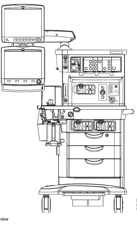
AB.75.253
Figure 1-1 • Front view
Serial numbers
Datex-Ohmeda products have unit serial numbers with coded logic which indicates a product group code, the year of manufacture, and a sequential unit number for identification. The serial number can be in one of two formats.
AAAX11111 AAAXX111111AA The X represents an alpha character
indicating the year the product was manufactured; H = 2004, J = 2005, etc. I and O are not used.
The XX represents a number indicating the year the product was manufactured; 04 = 2004, 05 = 2005, etc.
Trademarks
Aisys, Carestation, Advanced Breathing System, ComWheel, D-fend, EZchange, Disposable Multi Absorber, Reusable Multi Absorber, PSVPro, SmartVent, Easy-Fil, Aladin, and Aladin2 are
registered trademarks of Datex-Ohmeda, Inc.
Other brand names or product names used in this manual are trademarks or registered trademarks of their respective holders.
Symbols used in the manual or on the equipment
Symbols replace words on the equipment, on the display, or in product manuals.
Warnings and Cautions tell you about dangerous conditions that can occur if you do not follow all instructions in this manual.
Warnings tell about a condition that can cause injury to the operator or the patient.
Cautions tell about a condition that can cause damage to the equipment. Read and follow all warnings and cautions.
Symbols used on the equipment
.
O2 Flush button O2 cell connection
Air Air
APL settings are approximate Anesthetic Gas Scavenging System
Maximum Vacuum
Serial number Stock number
Exhaust Bellows volumes are approximate
Plus, positive polarity Minus, negative polarity
Maximum mass of configured mobile equipment
Caution: federal law prohibits dispensing without prescription. Autoclavable
On (power) Off (power)
Standby Interference
Type BF equipment Type B equipment
Dangerous voltage Frame or chassis ground
Protective earth ground Earth ground
Direct current Alternating current
Caution Refer to instruction manual or booklet
Operating instructions General warning (yellow background)
Electrical input/output Sample gas inlet to scavenging
Pneumatic inlet Pneumatic outlet
Equipotential Lamp, lighting, illumination
Variability Variability in steps
Suction bottle outlet Vacuum inlet
Bag position/manual ventilation Mechanical ventilation
Inspiratory flow Expiratory flow
Movement in one direction Movement in two directions
Lock Unlock
Open drain (remove liquid) Low pressure leak test
This way up Not autoclavable
Read to center of float EZchange canister (CO2 bypass)
Systems with this mark agree with the European Council Directive (93/42/ EEC) for Medical Devices when they are used as specified in their User’s Reference manuals. The xxxx is the certification number of the Notified Body used by Datex-Ohmeda’s Quality Systems.
Authorized representative in the European Community
Indicates that the waste of electrical and electronic equipment must not be disposed as unsorted municipal waste and must be collected separately. Please contact an authorized
representative of the manufacturer for information concerning the
decommissioning of equipment.
GOST R Russian certification
Stepping prohibited When moving or transporting
anesthesia machine, place the display arm and shelf in the transport position as shown.
Device contains phthalates XXXX indicates phthalate Possible phthalates include: DBP: Di-n-butyl phthalate
DNPP: 1,2-Benzenedicarboxylic acid, dipentylester, branched and linear; N-pentyl-isopentylphthalate; Di-n-pentyl phthalate; Diisopentylphthalate BBP: Benzyl butyl phthalate
DEHP: Bis(2-ethylhexyl) phthalate; Di-(2-ethylhexyl) phthalate
DMEP: Bis(2-methoxyethyl) phthalate DIBP: Dissobutyl phthalate
Single use device
Union made Stacking limit by mass
Keep dry Do not stack
Temperature limitation Fragile, handle with care
Protect from heat and radioactive sources
Recyclable material
Humidity limitation Electrical test certification
USB port Network
Not a USB port VGA connection
Atmospheric limitation
Symbols used on the user interface
.
Lock
Indicates the touchscreen is locked.
Lock/unlock button
Button label to lock or unlock the touchscreen.
O2% indicator on left and balance gas indictor on right. Colors associated with gas settings.
Gas indicator. Color associated with gas settings.
Audio Pause Submenu
No battery/battery failure Battery in use. Bar indicates amount of
battery power remaining.
Airway module indicator ACGO active
Drop-down menu Start/end case
Pediatric Adult
Lung procedure Home screen
Timer Alarm off
Pipeline Cylinder
Test indicator: red for failure, yellow for conditional outcome, and green for pass.
Alarm low and alarm high limit indicator
Manual ventilation Enhanced temperature sensing
Agent level sensing supported. Bar indicates amount of agent remaining.
Typeface conventions used
Soft keys and menu items are written in bold italic typeface; for example, System Setup.
Messages that are displayed on the screen are enclosed in single quotes; for example, ‘Check sample gas out’.
When referring to different sections and other documents, the names are written in italic typeface and enclosed in double quotes; for example, "System controls and menus".
Abbreviations
Abbreviation Definition
A
AA Anesthetic agent
ABS Advanced breathing system
ACGO Auxiliary common gas outlet
AGSS Anesthesia gas scavenging system
Alt O2 Alternate O2
APL Adjustable pressure-limiting
APN Apnea
ATPD Ambient temperature and pressure, dry humidity
conditions
B
BTPS Body temperature, ambient pressure, saturated humidity
conditions
C
CGO Common gas outlet
CO Carbon monoxide
CO2 Carbon dioxide
Compl Compliance
CPAP + PSV Continuous positive airway pressure + pressure support
ventilation
E
EMC Electromagnetic Compatibility
ET End-tidal concentration
EtCO2 End-tidal carbon dioxide
EtO2 End-tidal oxygen
Exp Expiratory
F
FI Fraction of inspired gas
FiCO2 Fraction of inspired carbon dioxide
FiO2 Fraction of inspired oxygen
Flow-Vol Flow-volume loop
I
I:E Inspiratory-expiratory ratio
Insp Inspiratory
Insp Pause Inspiratory pause time
K
kg Kilogram
Abbreviation Definition
MAC Minimum alveolar concentration
MV Minute volume
MVexp Expired minute volume
MVinsp Inspired minute volume
N
N2O Nitrous oxide
O
O2 Oxygen
P
Paw Airway pressure
PCV Pressure control ventilation
PCV-VG Pressure control ventilation - volume guaranteed
PEEP Positive end expiratory pressure
Paw-Flow Pressure-flow loop
Pinsp Inspiratory pressure
Pmax Maximum pressure
Pmean Mean pressure
Ppeak Peak pressure
Pplat Plateau pressure
Psupport Support pressure
PSV Pressure support ventilation
PSVPro Pressure support ventilation with apnea backup
Paw-Vol Pressure-volume loop
R
Raw Airway resistance
RF Radio frequency
RR Respiratory rate
S
SIMV PCV Synchronized intermittent mandatory ventilation
-pressure control ventilation
SIMV PCV-VG Synchronized intermittent mandatory ventilation
-pressure control ventilation - volume guaranteed
SIMV VCV Synchronized intermittent mandatory ventilation - volume
control ventilation
T
Texp Expiratory time
Tinsp Inspiratory time
Tpause Time where breath is paused with no flow
TV Tidal volume
TVexp Expired tidal volume
TVinsp Inspired tidal volume
Abbreviation Definition
VCV Volume control ventilation
System information
System classification
This system is classified as follows: • Class I Equipment.
• Type B Equipment.
• Type BF Equipment (airway modules). • Ordinary Equipment.
• Not for use with flammable anesthetics. • Continuous operation.
Device standards IEC 60601-1:2005
Devices used with this anesthesia system shall comply with the following standards where applicable:
• Breathing system and breathing system components ISO 80601-2-13.
• Anesthetic gas scavenging systems ISO 80601-2-13 • Anesthetic vapor delivery devices ISO 80601-2-13. • Anesthetic agent monitors ISO 80601-2-55. • Oxygen monitors ISO 80601-2-55.
• Carbon dioxide monitors ISO 80601-2-55. • Exhaled volume monitors ISO 80601-2-13.
Device standards IEC 60601-1:1988
Devices used with this anesthesia system shall comply with the following standards where applicable:
• Breathing system and breathing system components ISO 8835-2.
• Anesthetic gas scavenging systems ISO 8835-3 • Anesthetic vapor delivery devices ISO 8835-4. • Anesthetic agent monitors ISO21647.
• Oxygen monitors ISO 21647. • Carbon dioxide monitors ISO 21647. • Exhaled volume monitors IEC 60601-2-13.
Integral system components
This anesthesia system contains the following integral components, monitoring devices, alarm systems, and protection devices that comply with European, international, and national standards: • Breathing system pressure-measuring device.
• Airway pressure-limitation device. • Exhaled-volume monitor.
• Breathing system integrity alarm.
• Breathing system continuing-pressure alarm. • O2 monitor (optional O2 cell).
• Anesthesia ventilator. • Breathing system.
• Anesthetic vapor delivery device.
Not integral system components
These devices are not integral to this anesthesia system: • CO2 monitor.
• Anesthetic agent monitor.
• O2 monitor (when O2 cell is not installed). • Suction regulator.
• EZchange canister system. • Condenser.
When adding devices to the anesthesia system, follow the installation instructions provided by the device manufacturer. Whoever adds individual devices to the anesthesia system shall provide instructions on how to enable the individual devices. For example, a preoperative checklist.
System accessories
These devices can be used as accessories on this anesthesia system:
• Suction regulator.
• EZchange canister system. • Condenser.
System safety
Preparing for use
Read each component’s User’s Reference manual and
understand the following before using this system:
•
All system connections.
•
All warnings and cautions.
•
How to use each system component.
•
How to test each system component.
Before using the system:
•
Complete all of the tests in the "Preoperative tests"
section.
•
Test all other system components.
•
If a test fails, do not use the equipment. Have an
authorized service representative repair the
equipment.
European, international, and national standards require
the following monitoring be used with this system:
•
Exhaled volume monitoring.
•
O2 monitoring.
•
CO2 monitoring.
•
Anesthetic agent monitoring be used when anesthetic
vaporizers are in use.
Single-use products are not designed or validated to be
reused. Reuse may cause a risk of cross-contamination,
affect the measurement accuracy, system performance,
or cause a malfunction as a result of the product being
physically damaged due to cleaning, disinfection,
re-sterilization, or reuse.
Be aware of the risks and precautionary measures
related to phthalates. The following types of procedures
may increase the risk of exposure to phthalates when a
WARNING
•
•
•
device containing phthalates is used for treatment of
children or treatment of pregnant or nursing women:
•
Exchange transfusion in neonates, total parenteral
nutrition in neonates, multiple procedures in sick
neonates, haemodialysis in peripuberal males, male
fetus and male infant of pregnant women, and
lactating women; and massive blood infusion into
trauma patients. Although these procedures have the
potential for increased risk of exposure, conclusive
evidence of human health risks has not been
established. As a precautionary measure, to reduce
the potential for unnecessary exposures to
phthalates, the product must be used in accordance
with the instructions for use, and practitioners should
refrain from using this product beyond the period of
time the product is medically necessary or needed.
Follow hospital procedures for the prevention and
treatment of malignant hyperthermia for patients sensitive
to inhalation anesthetic agents.
Risk of fire. Limit the use of supplemental oxygen
concentrations to less than 30 percent when using a heat
source or device that may lead to combustion. Consult
facility risk management procedures to minimize the risk
of fire if an oxygen concentration of more than 30 percent
is required for any reason.
This system is not intended for use where the
surrounding oxygen concentration is in excess of 25
percent. Increased oxygen concentrations can result in
an increased risk of fire.
See "Device standards IEC 60601-1 2005" and "Integral system
components" for information regarding monitoring built into this
device.
Inspecting the system
Before using the system, make sure that: • The equipment is not damaged. • Components are correctly attached.
• The breathing circuit is correctly connected and not damaged. • The breathing system is correctly assembled and contains
sufficient absorbent. Refer to the “Cleaning and Sterilization” manual for breathing system assembly instructions.
• The Aladin cassette is locked in position and contains sufficient agent.
•
•
• Pipeline gas supplies are connected and the pressures are correct.
• Cylinder valves are closed.
• Models with cylinder supplies have a cylinder wrench attached to the system.
• Models with cylinder supplies have a reserve supply of O2 connected to the machine during system checkout.
• The necessary emergency equipment is available and in good condition.
• Equipment for airway maintenance, manual ventilation, tracheal intubation, and IV administration is available and in good condition. In the case of system failure, the lack of immediate access to alternative means of ventilation can result in patient injury.
• Applicable anesthetic and emergency drugs are available. • Check that the brake is set to prevent movement.
• The power cord is connected to an electrical outlet. The mains indicator comes on when AC power is connected. If the indicator is not on, the system does not have mains (electrical) power. Use a different outlet, close the circuit breaker, or replace or connect the power cable.
• If an optional suction regulator is present, ensure there is adequate suction.
• If an optional O2 flowmeter is present, ensure there is adequate flow.
Electrical safety
Do not connect non-medical electrical equipment directly to the AC outlet at the wall instead of an AC power source which uses a separating transformer. Doing so may increase enclosure leakage current above levels allowed by IEC 60601-1 in normal conditions and under single-fault conditions. This may cause an unsafe electrical shock to the patient or operator.
After connecting anything to these outlets, conduct a complete system leakage current test (according to IEC 60601-1).
The system provides connections for items such as
printers, visual displays and hospital information
networks (only connect items that are intended to be part
of the system). When these items (non-medical
equipment) are combined with the system, these
precautions must be followed:
•
Do not place items not approved to IEC 60601-1
closer than 1.5 m to the patient.
•
All items (medical electrical equipment or
non-medical electrical equipment) connected to the
system by a signal input/signal output cable must be
supplied from an AC power source which uses a
separating transformer (in accordance with IEC
60989) or be provided with an additional protective
earth conductor.
•
If a portable multiple socket outlet assembly is used
as an AC power source, it must comply with IEC
60601-1-1. The assembly must not be placed on the
floor. Using more than one portable multiple socket
outlet assembly is not recommended. Using an
extension cord is not recommended.
An operator of the medical electrical system must not
touch non-medical electrical equipment and the patient
simultaneously. This may cause an unsafe electrical
shock to the patient.
Use of portable phones or other radio frequency (RF)
emitting equipment (that exceed electromagnetic
interference levels specified in IEC 60601-1-2) near the
system may cause unexpected or adverse operation.
Monitor operation when RF emitters are in the vicinity.
Use of other electrical equipment on or near this system
may cause interference. Verify normal operation of
equipment in the system before use on patients.
•
•
System controls and menus
System overview. . . .2-2 Advanced breathing system components. . . 2-6 Aladin cassette controls. . . 2-8 Display controls. . . .2-9 Anesthesia system display. . . 2-12 Display navigation. . . .2-15
System overview
2 3 4 5 6 7 10 8 11 12 13 14 15 1 9 A B. 75 .2511. Patient monitoring modules 9. Aladin cassette storage bay
2. Dovetail 10. Brake
3. Aladin cassette and active bay 11. O2 flush button
4. Light switch 12. Advanced breathing system
5. Alternate O2 control 13. Auxiliary O2 flow control
6. System switch 14. Anesthesia display
7. Mains indicator 15. Patient monitoring display
8. Integrated suction
1 2 3 4 5 6 7 8 9 10 11 AB.75.255
1. Serial port 7. Mains inlet
2. Collection bottle connection 8. System circuit breaker
3. Cylinder wrench (key) storage 9. Equipotential stud
4. Cylinder yoke 10. Outlet circuit breaker
5. Anesthesia Gas Scavenging System 11. Isolated electrical outlet
6. Pipeline connections
Using the brake
The central brake holds the system in place.
Do not use the brake while moving the anesthesia
system. This could cause the machine to tip over. Only
use the brake to keep the system in place.
AC.22.009
1. Push down on the brake pedal to lock the system in place. 2. Lift up on the brake pedal to release the brake.
Using the O2 flush button
The O2 flush button supplies a high flow of O2 to the breathing system.
1. Push the O2 flush button to deliver a high flow of O2.
2. Release the O2 flush button to stop the delivery of a high flow of O2.
Positioning the display
The display can be moved for optimal viewing. 1. Unlock the display arm.
2. Raise or lower the display arm to adjust the height of the display.
3. Lock the display arm.
4. Rotate the display arm toward or away from the system to adjust the horizontal position of the display.
5. Tilt the display up or down to adjust the vertical angle of the display.
6. Tilt the display left or right to adjust the horizontal angle of the display.
Advanced breathing system components
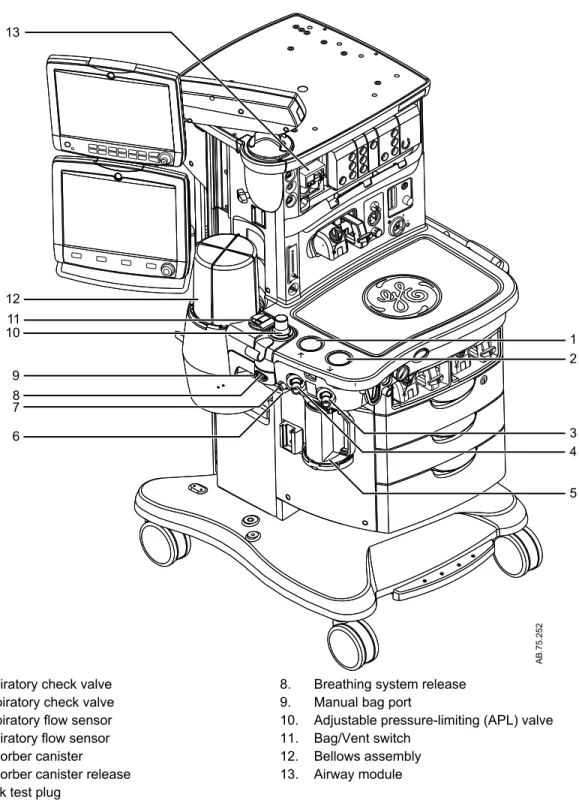
1 2 3 4 5 6 7 8 1011 12 13 AB.75.252 91. Expiratory check valve 8. Breathing system release
2. Inspiratory check valve 9. Manual bag port
3. Inspiratory flow sensor 10. Adjustable pressure-limiting (APL) valve
4. Expiratory flow sensor 11. Bag/Vent switch
5. Absorber canister 12. Bellows assembly
6. Absorber canister release 13. Airway module
7. Leak test plug
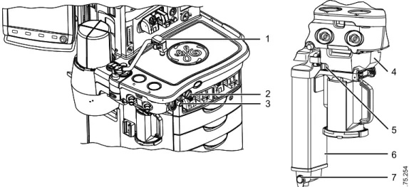
AB.75.254 4 5 6 7 1 2 3
1. Bag support arm
2. Auxiliary Common Gas Outlet (ACGO) switch
3. ACGO port
4. EZchange canister module (CO2 bypass)
5. Ezchange canister release
6. Condenser
7. Condenser drain button
Figure 2-4 • Breathing system options
Using the bag support arm
Use the optional bag support arm to hold the breathing circuit bag.
AB.82.023
1. To raise the bag support arm, squeeze the button and rotate the arm up the top position.
2. To lower the bag support arm, squeeze the button and rotate the arm down to the lower position.
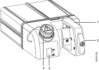
Aladin cassette controls
The electronically controlled vaporizer consists of the internal electronic control unit and the Aladin agent cassette. See the "Vaporizer" section for more information.
1
2
3 4
AB.60.038
1. Handle with release trigger
2. Lock
3. Liquid level indicator
4. Agent filling port
Display controls
The system uses touchscreen technology, hard keys, and a ComWheel to access system functions, menus, and settings. The touchscreen has numerous touch point areas that make accessing menus and settings quick and easy. The buttons on the right side of the screen provide direct access to commonly used functions. The ventilation quick keys enable setup of ventilation modes. The gas control quick keys provide a method to set up the gas used for a case.
Touch only one touch point at a time to ensure the correct selection is made.
Liquids on the display may degrade the performance of
the touchscreen. If liquids come in contact with the
display, lock the touchscreen and clean the display.
Unlock the touchscreen once the display has been
cleaned to resume use of the touchscreen.
Do not apply excessive force to the touchscreen as
damage may occur.
6 5 4 3
AC.22.001
2 1
1. ComWheel Selects a menu item or confirms a setting. Turn clockwise or counterclockwise to scroll
through menu items or change settings.
2. Home key Removes all menus from the screen.
3. Screen Lock/Unlock
key
Locks the touchscreen. Toggles between lock and unlock functions.
4. Start/End Case key Initiates Start or End Case function.
5. Touchscreen Activates functions when touch areas on the screen are selected.
WARNING
6. Audio Pause key Stops audio for 120 seconds for any active, eligible high and medium priority alarms. Prevents audio (audio off) for 90 seconds when no medium or high priority alarms are active. Allows the operator to acknowledge any non-active medium or high priority latched alarms.
Figure 2-6 • Display controls
Touch points
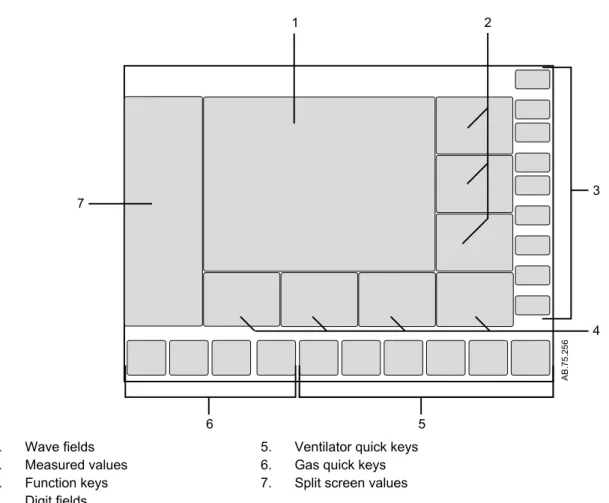
AB.75.256 2 1 3 4 5 6 71. Wave fields 5. Ventilator quick keys
2. Measured values 6. Gas quick keys
3. Function keys 7. Split screen values
4. Digit fields
Figure 2-7 • Normal/Full screen view with shaded touch point areas
Measured value touch points
Touching measured values provides access to the Alarm Setup menu and alarm limits.
1. Touch the measured value to access the Alarm Setup menu. 2. The Alarm Setup menu displays.
3. Select the alarm limit and set it to the correct value. Touch the value on the touchscreen or push the ComWheel to confirm the desired setting.
4. Push the Home key, touch the waveform area of the display, or select Close to close the menu.
Active alarm touch points
When an alarm sounds the alarm message is displayed at the top of the screen and, if applicable, the alarming numeric field and digit field flashes. The Alarm messages at the top of the screen are message alerts only and not active touch points.
1. Touch the flashing numeric field to access the Alarm Setup menu and alarm limits for the active alarm.
2. The Alarm Setup menu displays with the active alarm limit highlighted. For example: If the ‘Ppeak high’ alarm activates, the high alarm limit setting for Ppeak displays with the highlight. 3. Select the active alarm limit and change it to the desired setting.
Anesthesia system display
12 2 1 7 9 11 5 6 3 8 10 AB.75.2581. Audio pause symbol and
countdown clock
Indicates when alarm audio is paused and the countdown clock until audio is on.
2. Alarm message fields Displays the active alarms.
3. Waveform fields Displays the waveforms of measured values. For example: Paw, Flow, and
CO2.
4. General message fields or lock
touchscreen indicator
Displays general messages and the touchscreen lock indicator.
5. Measured values fields Displays the measured values. For example: Paw, Flow, and CO2.
6. Clock Displays the current time.
7. Function keys Functions available are: Audio Pause, Alarm Setup, Alarms On/Off, Auto
Limits, System Setup, Next Page, Trends, Spirometry, Procedures, Timer, Start, and End Case.
8. Digit fields Contains information for Spirometry, Resp, Agent, and Gases.
9. Ventilation mode Displays the selected ventilation mode. For example: Ventilator On, and
Volume Control.
10. Ventilator quick keys Displays Mode, associated ventilation parameters, and More Settings. For
11. Gas quick keys Displays O2, Total Flow, and Gas Setup.
12. Split screen Contains airway pressure, gas flow values, compliance, trends, and optional
ecoFLOW information.
Figure 2-8 • Typical Normal/Full view
Digit fields
The digit field can be set to show specific information such as gas types, gas supply, flow, agent, respiration, and spirometry loops. If the digit field is set to show agent and no airway module is inserted, the area is blank.
Paw, O2, and either TVexp or CO2 must show on the display during a case. If any of these parameters are not selected to show on the display, the right most digit field information is replaced with the missing parameter.
See "Screen setup menu" in the "Operation" section for more information.
Waveform fields
Up to three waveforms can be shown on the normal screen view. Each waveform can be set to show specific Paw, agent, flow, or CO2 data. The corresponding numeric information shows in the measured values field to the right of the waveform. If the waveform is set to show the agent and no airway module is inserted, that waveform and numeric area is blank.
When one waveform is turned off, that waveform and the
corresponding numerics information are removed from the normal screen view. The remaining waveforms and numerics increase in size to fill the waveform area. When two waveforms are turned off, those waveforms and the corresponding numerics information are removed from the normal screen view. The remaining waveform is centered in the waveform area.
When in a case, touch the waveform field area to close the menu. See "Screen setup menu" in the "Operation" section for more information.
Split screen field
The split screen field can be set to show gas metabolics, trends, spirometry loops, Paw gauge, airway compliance, and optional ecoFLOW information. If None is selected, the waveforms expand to
Touch the spilt screen field to directly open the Screen Setup menu. See "Screen setup menu" in the "Operation" section for more information.
Display navigation
Use the touchscreen and ComWheel to navigate the display.
AB.75.257
3
2
1
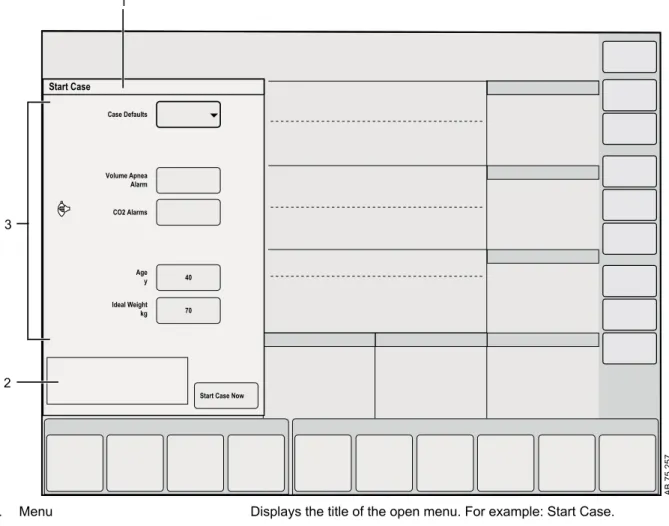
1. Menu Displays the title of the open menu. For example: Start Case.
2. Instructions or help information This shows any additional instructions or help messages.
3. Menu items Shows Case Defaults, Volume Apnea Alarm, CO2 Alarms, Age, Ideal
Weight, and Start Case Now.
Figure 2-9 • Menu view and menu example
Using menus
Use the function keys to access the corresponding menus. When a menu is selected, the menu field overlays the normal view and the waveform fields start at the right edge of the menu.
2. Select a menu item to choose the item, or turn the ComWheel left or right to highlight a menu item and then push to confirm. 3. If the menu item selected is an adjustment, turn the ComWheel
left or right to make the setting and then push to confirm. If the menu item has a drop-down list, select the desired value from the list by touching the item.
4. Select Close, touch the waveform area, or push the Home key to exit the menu.
Using the ComWheel
Use the ComWheel to scroll through the quick key settings and function keys, make selections, change settings, and confirm settings.
• Push the ComWheel to make a selection. • Turn the ComWheel to the right.
For menu items, the highlight moves down.
For quick keys, the highlight moves to the next key on the right. For settings, the value changes to the next available setting. For pull-down selections, the highlight moves to the next available selection.
• Turn the ComWheel to the left.
For menu items, the highlight moves up.
For quick keys, the highlight moves to the next key on the left. For settings, the value changes to the previous available setting. For pull-down selections, the highlight moves to the previous available selection.
• Push the ComWheel to confirm a setting.
Using quick keys
The gas settings and the main ventilator settings for each ventilation mode can be changed using the quick keys.
1. Select a quick key to open the menu or select a parameter. 2. If Gas Setup, Mode, or More Settings is selected, a menu
displays. Select the desired value on the menu by touching the value.
If any other quick key is selected, the value displays with a highlight. Turn the ComWheel left or right to set the desired value.
3. Push the ComWheel or select the quick key to confirm the change.
Operation
System operation safety. . . 3-2 Turning on the system. . . 3-3 Start a case. . . 3-4 Turning off the system. . . 3-7 Ventilator setup. . . 3-8 Auto limits. . . 3-9 Gas setup. . . 3-10 System setup. . . 3-13 Alarm setup. . . .3-17 Alarms On Off. . . 3-21 Next page. . . 3-22 Trends. . . 3-23 Spirometry. . . .3-24 Procedures. . . 3-27 Timer function. . . 3-31 ecoFLOW. . . 3-32 Alternate O2 control. . . 3-34 EZchange canister mode. . . 3-36 Condenser. . . .3-38 Auxiliary Common Gas Outlet. . . 3-40
System operation safety
Do not use antistatic or electrically-conductive breathing
tubes or masks. They can cause burns if used near
high-frequency surgical equipment.
Explosion Hazard. Do not use this system with flammable
anesthetic agents.
Ventilator alarms indicate potential hazard conditions.
Investigate all alarms that occur to help ensure adequate
patient safety.
If an alarm occurs, safeguard the patient first before
performing troubleshooting or doing repair procedures.
Failure to safeguard the patient could result in patient
injury.
Make sure that the patient breathing circuit is correctly
assembled and that the ventilator settings are clinically
appropriate before starting ventilation. Incorrect breathing
circuit assembly and incorrect ventilator settings can
injure the patient.
Make sure that the breathing circuit is correctly
connected and not damaged. Replace the breathing
circuit if it is damaged.
Maintain sufficient fresh gas flow when using
sevoflurane.
Desiccated (dehydrated) absorbent material may
produce dangerous chemical reactions when exposed to
inhalation anesthetics. Adequate precautions should be
taken to ensure that absorbent does not dry out. Turn off
all gases when finished using the system.
Do not leave gas cylinder valves open if the pipeline
supply is in use. Cylinder supplies could be depleted,
leaving insufficient reserve supply in case of pipeline
failure.
Unplug the system power cord to run the system on the
battery power if the integrity of the protective earth
conductor is in doubt.
The top shelf weight limit is 45 kg (100 lb).
Do not subject the system to excessive shock and
vibration. Equipment damage could occur.
Do not place excessive weight on flat surfaces or
drawers. Equipment damage could occur.
WARNING
•
•
•
•
•
•
•
•
•
•
•
•
Turning on the system
1. Plug the power cord into an electrical outlet. Make sure the system circuit breaker is on.
• The mains indicator is lit when AC power is connected. • Battery is charging if it is not already fully charged.
1 2
AB.91.044
1. System switch
2. Mains indicator
Figure 3-1 • Mains indicator and system switch
2. Check that the breathing system is properly connected.
Do not turn on the system with the right-hand
(inspiratory) port plugged.
--3. Turn the System switch to On.
The display shows the power-up screen.
The system does a series of automated self tests. 4. Perform a Full Test before the first case of the day.
5. Perform a preoperative checkout before each case. See the "Preoperative checkout" section.
The system must perform a power-up self test after 12 hours of remaining on. If the system has been on longer than 12 hours without a power-up self test, the ‘Turn power Off and On for self tests’ alarm occurs. Turn the power off and then back on between cases to resolve the alarm.
--CAUTION
Start a case
Use the Start Case menu to set the case data and to start the gas flow.
A case can be started using default settings or using custom
settings. The default settings are configured by the Super User. See the "Super user mode" section for information on the Start Case menu defaults.
Default Settings selection shows the first of five default case types when the Start Case menu is accessed. Four of the default case types are configured by the Super User. The fifth default case is Last Case.
The Ideal Weight, Age, and Volume Apnea Alarm values are set to the pre-selected settings defined by the Super User corresponding to the case type.
Make sure that the patient breathing circuit is correctly
assembled and that the ventilator settings are clinically
appropriate before starting ventilation. Incorrect breathing
circuit assembly and incorrect ventilator settings can
injure the patient.
Make sure that the preset alarm limits are appropriate for
the patient before starting ventilation. Incorrect alarm
settings can injure the patient.
Volume Apnea Alarm is not shown on the Start Case menu when
the Volume Apnea Selection is set to Disable in the Super User settings.
The TV for Ideal Body Weight menu item from the Patient
Demographics menu can only be accessed when the ventilation
mode is set to VCV, PCV-VG, SIMV VCV, and SIMV PCV-VG. Use this setting for breath rate and tidal volume calculations based on the set patient weight.
Minimum Alveolar Concentration
The adjusted Minimum Alveolar Concentration (MAC) is calculated based on the patient age entered in the Start Case menu or the
Patient Demographics menu. The default patient age of the
selected case type is used if no patient age value is entered.
The MAC value is calculated from the exhaled gas concentration and the related affects based on the age of the patient. Typically,
younger patients have better liver function and can clear a drug faster, resulting in a higher MAC value. The MAC calculation used is based on the Eger formula. When two agents are detected, the MAC values of each agent are added together. The MAC value range is 0.0 to 9.9.
WARNING
•
Note
The adjusted MAC value shows on several areas of the screen including in the mini-trend, agent waveform numeric information, agent digit field, and graphical trends page.
Starting a case using default settings
Start a case using the default settings by case type defined by the Super User.
Case Defaults contain five case type selections. Each case type has preset values for Ideal Weight, Age, and Volume Apnea Alarm. The first four default case types are configured and named by the Super User. The fifth default case is Last Case.
1. Set the Bag/Vent switch to Bag. 2. Select Start Case.
The Case Defaults selection shows the first preset case type.
Ideal Weight, Age, CO2 Alarms, and Volume Apnea Alarm
show the default settings that correspond to the case type shown.
3. Verify or change the Case Defaults selected. 4. Verify the settings are clinically appropriate. 5. Select Start Case Now. Gas flow starts.
Starting a case using custom settings
Ideal Weight, Age, CO2 Alarms, and Volume Apnea Alarm can be
custom set on the Start Case menu before starting a case. Additional ventilator settings, ventilation mode, alarm settings, and gas settings can be custom set through the Vent Mode menu and other ventilation quick keys, Alarm Setup menu, Gas Setup menu. 1. Set the Bag/Vent switch to Bag.
2. Select Start Case.
The Case Defaults selection shows the first preset case type.
Ideal Weight, Age, CO2 Alarms, and Volume Apnea Alarm
show the default settings that correspond to the case type shown.
3. Change Ideal Weight, Age, or Volume Apnea Alarm settings on the menu.
The Case Defaults changes from the case name to Preset. If the CO2 Alarms setting on the menu is changed, the Case
4. To change ventilation mode, select Mode. Make the change.To change the ventilation settings, select a ventilator quick key or
More Settings. Make the change.
5. To change alarm settings, select Alarm Setup. Make the change.
6. To change the gas settings or the circuit type, select Gas Setup. Make the change.
7. From the Start Case menu, select Start Case Now. Gas flow starts.
See the "Ventilator setup" section for information on the Vent Mode menu.
See the "Gas setup" section for information on the Gas Setup menu. See the "Alarm setup" section for information on the Alarm Setup menu.
End a case
Use the End Case menu to stop gas flow and end the patient alarms.
1. Set the Bag/Vent switch to Bag. 2. Select End Case.
3. Select End Case Now on the menu to put the system in standby (stops the gas flow and patient alarms). The End Case menu shows the gas and agent usage for the case.
Turning off the system
1. Perform the "End a case" procedure, if appropriate. 2. Turn the System switch to Standby.
3. Turn the suction switch (optional) to the off position.
4. Rotate the Auxiliary O2 knob fully clockwise to turn off the flow. 5. Disconnect or turn off any scavenging.
Ventilator setup
Use the Vent Mode menu to set the ventilation mode. Use ventilator quick keys and More Settings to change ventilator settings.
Most anesthetic agents will cause patients to have
reduced ventilatory responses to carbon dioxide and to
hypoxemia. Therefore, triggered modes of ventilation
may not produce adequate ventilation.
The use of neuromuscular blocking agents will reduce
the patient’s breathing response, which will interfere with
triggering.
See the "Specifications and theory of operation" section for more information on ventilation modes.
Changing ventilator mode
1. Select the Mode quick key. The Vent Mode menu shows. 2. Select the desired ventilation mode.
3. Set and confirm the primary ventilation setting to activate the ventilation mode.
Controls that are frequently used in the ventilation mode can be adjusted with the ventilator quick keys and the More Settings quick key.
Changing ventilator settings
Change the ventilator settings for the ventilation mode when a case is running.
1. Select the ventilation setting to be adjusted. Set the desired value.
2. Push the ComWheel to activate the change.
Optional ventilator procedures
See "Procedures" for more information on Vital Capacity and
Cycling procedures.
WARNING
•
Auto limits
Use the Auto Limits menu to quickly set alarm ranges for ‘MV’, ‘TV’, and ‘EtCO2’ during mechanical ventilation.
Setting auto limits
1. Select Auto Limits.
The menu shows the current measured values and the proposed low and high alarm limits.
2. Check the proposed parameters.
• Select Confirm to use the proposed low and high alarm limits.
• Select Cancel to leave the alarm limits unchanged. • Select Case Default Limits to set the alarm limits to the
case default limits.
The proposed low and high alarm limits are shown in highlighted text. The alarm limits that are not highlighted do not change.
Gas setup
Use the Gas Setup menu to adjust the Agent, O2% and total flow, to change the balance gas, and to change the circuit type.
Changing gas settings
1. Select the Gas Setup quick key.
2. Select the setting to change from the Gas Setup menu. 3. Change the setting.
4. For Circuit, select the menu item and change using the drop-down menu. Select Confirm.
5. For Other Gas, select the menu item and change using the drop-down menu.
6. For Agent, O2%, and Total Flow, select the setting and make the change using the ComWheel and push to confirm the setting.
Changing balance gas
1. Select the Gas Setup quick key. 2. Select the Other Gas menu item. 3. Select the balance gas to use with O2.
Changing circuit type
1. Select the Gas Setup quick key. 2. Select Circle or Non-Circle 3. Select Confirm.
Using the circle circuit
Use the circle circuit mode to combine fresh gas with recirculated gas from the CO2 absorber. The combined gas flows out through the inspiratory port. Patient gas is returned to the system through the expiratory port.
Mechanical ventilation and tidal volume monitoring are available when using the circle circuit.
O2 monitoring of fresh gas is available automatically when using the circle circuit if the system has the airway module option or the O2 cell monitoring option. Systems with both an airway module and an O2 cell will display the O2 values obtained from the airway module. 1. Select the Gas Setup quick key.
2. Select Circle.
Fresh gas oxygen concentration is displayed on the screen. Fresh gas flow combines with the exhaled gas and exits out through the inspiratory port.
3. Set the alarm limits to clinically appropriate settings.
Using the non-circle circuit
Use the non-circle circuit mode to divert fresh gas around the inspiratory check valve and out through the inspiratory port. This fresh gas source may be used with circuits that do not have CO2 absorbent capability (for example, Mapleson variants). Mechanical ventilation is not available when using the non-circle circuit. Tidal volume monitoring is not available when using the non-circle circuit. O2 monitoring of fresh gas is available automatically when using the non-circle circuit if the system has the airway module option or the O2 cell monitoring option. Systems with both an airway module and an O2 cell will display the O2 values obtained from the airway module.
Do not use an external ventilator when using the
non-circle circuit. Do not use the non-non-circle circuit to drive
external ventilators or for jet ventilation.
The maximum pressure at the non-circle circuit can be up
to 27 kPa (4 psi). Use a breathing circuit with a pressure
limiting device to limit the pressure at the patient
connection port, during normal and single-fault
conditions, to less than 12.5 kPa (125 cmH2O) or to the
maximum pressure required by local standards.
1. Select the Gas Setup quick key. 2. Select Non-Circle.
Fresh gas oxygen concentration is displayed on the screen. Fresh gas flow is diverted around the inspiratory check valve and out through the inspiratory port.
WARNING
System setup
Use System Setup to access menus and settings for Patient
Demographics, Screen Setup, Fresh Gas Usage, System Status, Calibration, and Checkout.
System Status shows the status of gas supplies, electrical supplies,
and the software version.
See the "User maintenance" section for information on the
Calibration menu item.
See the "Preoperative tests" section for information on the Checkout menu item.
Patient demographics
Use the Patient Demographics menu to access menus and settings for Age, Ideal Weight, TV for Ideal Body Weight, and Set Vent by
Weight.
Screen setup menu
Use the Screen Setup menus to customize the screen view. Areas of the screen can be customized to show specific information.
Screen Setup contains the Layout, Scales, Time and Date, and More Settings submenus.
Setting waveform fields
The waveforms can be set to show agent, CO2, flow, Paw, or set to Off. If a waveform is set to the same value as another waveform, the previously set waveform changes to off and is removed from the screen.
1. Select System Setup - Screen Setup. 2. Select the Layout tab.
3. Select the desired waveform button and select the value from the drop-down menu.
4. Select Close.
Setting digit fields
The digit field can be set to show gas supply, flow, spirometry loops, gases, respiration, or agent. If the digit field is set to show agent and no airway module is inserted, the digit field will be blank.
1. Select System Setup - Screen Setup. 2. Select the Layout tab.
3. Select the desired digit field button and select the value from the drop-down menu.
4. Select Close.
Setting the split screen
Use the Split Screen setting to show metabolics, trends, spirometry loops, Paw gauge, airway compliance, and optional ecoFLOW information.
See the "ecoFLOW" for information on the ecoFLOW option. Resistance (Raw) shows in the airway compliance split screen when the system detects an airway module with spirometry and the module has completed a warm-up phase.
1. Select System Setup - Screen Setup. 2. Select the Layout tab.
3. Select Split Screen and select the desired view from the drop-down menu.
4. Select Close.
Setting time and date
Use the Time and Date menu to set the time and date. The Time and Date menu cannot be changed when a case is running.
1. Select System Setup - Screen Setup. 2. Select the Time and Date tab.
3. Select the time or date item to change. Make the change. The clock format factory default is 24 hours.
• When the clock format is set to 12 h, the hour selections are in ‘1a’ format for a.m. and ‘1p’ format for p.m.
• When the clock format is set to 24 h, the hour selections are 0 to 23 in one hour increments.
4. Select Close.
Setting the data source
Use Data Source to specify the source of spirometry data. 1. Select System Setup - Screen Setup - More Settings or
Spirometry - Setup Loops.
2. Select Data Source.
Note
3. Select Patient to have spirometry data sourced from the airway module or Vent to have spirometry data sourced from the ventilator.
4. Select Back to view changes made and access other functions of the Spirometry menu.
Setting sweep speed
Use the Sweep Speed setting to set the waveform draw rate to fast (6.25 mm/s) or slow (0.625 mm/s). When the sweep speed changes, waveforms redraw at the new rate.
1. Select System Setup - Screen Setup. 2. Select More Settings.
3. Select Sweep Speed and then select Fast or Slow. 4. Select Close.
Setting display brightness
Use the brightness setting to adjust the contrast level of the display. 1. Select System Setup - Screen Setup.
2. Select More Settings. 3. Select Display Brightness.
4. Select the desired brightness level with 1 being the dimmest and 5 being the brightest.
5. Select Close.
Setting keypad brightness
Use the brightness setting to adjust the contrast level of the hard keys on the bezel.
1. Select System Setup - Screen Setup. 2. Select More Settings.
3. Select Keypad Brightness.
4. Select the desired brightness level with 1 being the dimmest and 5 being the brightest.
Set to 0 to turn off the keypad brightness. 5. Select Close.
Setting fresh gas controls
Use the Fresh Gas Controls selection to set the gas control style to O2% with Total Flow or to individual gas flow.
Selecting O2% shows O2% as the first quick key and Total Flow l/min as the second quick key.
Selecting Flow shows balance gas l/min as one of the quick keys and O2 l/min as the other quick key.
Both O2% and Flow are available if User is selected by the Super User. If User is not selected by the Super User, either O2% or Flow will be unavailable.
Fresh Gas Controls cannot be accessed during a case.
1. Select System Setup - Screen Setup. 2. Select More Settings.
3. Select Fresh Gas Controls.
4. Select O2% or Flow from the drop-down menu.
When set to O2%, balance gas adjusts automatically when either the O2% or the Total Flow is changed using the gas quick keys.
When set to Flow, balance gas and the O2% are controlled individually using the gas quick keys.
5. Select Close.
Fresh gas usage
Use Fresh Gas Usage to view the volume of O2, Air, N2O, and agents used for the three most recent cases.
• Data only shows for gases available on the system. • Agent data shows the three most recently used agents.
1. Select System Setup - Fresh Gas Usage.
2. Select Case Start Time to select the patient case to view. 3. Select Close.
Note