HAL Id: halshs-00264181
https://halshs.archives-ouvertes.fr/halshs-00264181
Submitted on 1 Apr 2008HAL is a multi-disciplinary open access archive for the deposit and dissemination of sci-entific research documents, whether they are pub-lished or not. The documents may come from teaching and research institutions in France or abroad, or from public or private research centers.
L’archive ouverte pluridisciplinaire HAL, est destinée au dépôt et à la diffusion de documents scientifiques de niveau recherche, publiés ou non, émanant des établissements d’enseignement et de recherche français ou étrangers, des laboratoires publics ou privés.
Semantic-based modelling and representation of
patrimony buildings
Livio de Luca, Philippe Véron, Michel Florenzano
To cite this version:
Livio de Luca, Philippe Véron, Michel Florenzano. Semantic-based modelling and representation of patrimony buildings. SVE Worksop towards Semantic Virtual Environments, Mar 2005, Villars, Switzerland. pp.1-11. �halshs-00264181�
Semantic-based modelling and representation of
patrimony buildings
Livio De Luca
Laboratoire MAP
UMR CNRS/MCC 694
[email protected]
www.map.archi.fr
Philippe Véron
Laboratoire LSIS
UMR CNRS 6168
[email protected]
www.lsis.org
Michel Florenzano
Laboratoire MAP
UMR CNRS/MCC 694
[email protected]
www.map.archi.fr
Abstract
This article presents a methodological approach for the semantic description of patrimony buildings based both on theoretical reflections and on research experiences. To develop this approach, a first process of extraction and formalisation of architectural knowledge based on the analysis of architectural treaties is proposed. Then, the identified features are used to produce a template shape library dedicated to the buildings surveying. Finally, the problem of the overall model structuration and organization using semantic information is addressed for user handling purposes.
Keywords: architectural heritage, architectural knowledge, feature-based modelling, virtual environments, semantic shape.
1. Introduction
Understanding studies of architectural heritage can be today widely improved by the use of 3D reconstruction of the real buildings. This way is also efficient to document historic buildings and sites for their reconstruction or restoration, to create resources for researchers and to analyze their historical evolutions.
The spatial data acquisition techniques have known in these last years large improvements due to the introduction of laser scanning technologies [1]. Nevertheless, if the digitizing phase can profit of automatic and high-speed procedures, the 3D point clouds post processing requires many manual actions when the objective is to produce an analytical representation of architectural objects. In fact, if this technical solution theoretically allows having an accurate geometric reproduction of a building with all its details, it remains still the problem of producing a semantically enriched model [2]. A triangulated-model can be widely
appropriate to represent artistic objects such as sculptures or facing relief [3]. But, when the definition of geometrical relations and rules between dimensions are required to describe the proportions of typical objects participating to an architectural project, this type of geometrical representation is not efficient. With regard to the set of classical architectural shapes, relevant information, which must be acquired, recognized and modelled, can be found in a set of relevant profiles describing these shapes on the basis of the conventions of architectural drawings.
Whatever the digitizing device used, before starting the treatment of the 3D data sets, it is essential to take into account the representation problems, because the reconstruction process carried out makes a geometrical interpretation of the architectural elements. Indeed, if the actual reconstruction techniques provide good surface reconstructions, they do not necessarily integrate the semantic interpretation of the architectural shapes. In this sense, the efficient proposed way to define an architectural surveying is to consider it as a rebuilding problem [4]. Architectural surveying is a reverse process which starts from the real object, rebuilds a digital model and interprets the idea which is upstream of its realization. In an architectural building project two essential points of views can be characterized. The first one is related to the architect who has an ideal and perfect design reference and the second one relates the concrete and imperfect real realization. In the same manner, the architectural surveying can be articulate around two points of views. The first one is related to the crude processing of the 3D data sets which produce an imperfect digital model and the second one is related to the exploitation of semantic information producing an enhanced design model of the real building.
In this way, the extraction of relevant information from the 3D digitized data, according to the architectural drawing conventions (related to the different historic periods), forms an important problem which must be addressed. To this end, semantic-based representations of patrimony buildings can thereby play an important role for the development of information systems in the architecture field. Beyond survey, in fact, the development of qualitative descriptions of architectural objects is a major research area. Nevertheless, if the scientific analysis of crude documentary sources has benefited from the development of various data management techniques, it has most often been done without a concern for graphical visualisation or for a clear reference to the architectural morphology. Architectural surveying and documentation seems to relate to totally independent research areas whereas they have naturally common problematic around the integration of information and knowledge associated to an edifice. Consequently, today it appears as essential to take into account and integrate quantitative information supported by the surveying process and qualitative information or knowledge extracted from documentation sources. The approach proposed, sets a method to formalize the theoretical knowledge of patrimony buildings which is then used to support the different investigation stages of an edifice, from 3D surveying to representation and handling in a 3D real-time environment. The paper is organized as follow. Section 2 discusses the problem of the semantic description of patrimony buildings. Section 3 describes the knowledge-based modelling tools developed, starting from a method for the feature formalisation from architectural treaties. Section 4 presents a result example of semantic-based representation for information interfacing. Finally, section 5 concludes the paper and suggests some future works.
2. Architectural knowledge system
The study of the drawing convention in the history of the architectural representation has a double finality: the first one leads to the representation and the second one leads to the object surveying. These two analysis points of views of the architectural elements are strictly interdependent [5]. The knowledge extraction problem consists in identifying the genesis of
the element shape to define, both, the appropriate way for its measurement and for its representation.
Figure 1: extract of the Palladio’s treaty of Architecture
To this end, architectural knowledge rules have to be formalised. An architectural knowledge system can be described as a collection of structured objects, identified through a precise vocabulary. Several studies led to the definition of classification methods for classical architectural elements.
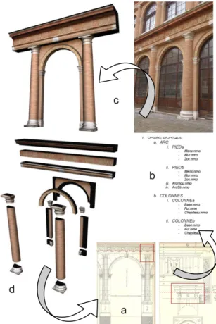
Figure 2: synthesis of the elements participating to a 3D building reconstruction process: (a) documentary sources, (b) formalized knowledge,
These are based on a structure of different level of abstraction of architectural space [6]. These classifications are based on the study of the architecture treaties, which organize the ‘art to build’ knowledge relatively to the different historical periods. Many treaties develop an identity coding of architectural elements. This identity is normally expressed through a hierarchical description of all the elements, which make a build unit (Fig.1).
In [7], by means of a representation convention, each architectural element is expressed by a geometrical description level (i.e. lines, curves), a topological relations level (i.e. parallelism, concentricity, etc) and a spatial relations level (i.e. proportions, harmonic reports/ratios). The problematic of the semantic description of patrimony buildings return to the extraction of these three levels starting from the 3D digitized data of a real building. It starts from the analysis of various sources (Fig.2 a) of knowledge (including the study of particular cases) to extract drawing rules. These rules are formalised (Fig.2 b) to produce their appropriate digital translation into a 3D semantic-based description (Fig.2 d). The semantic description of an architectural element gathers modelling functions, constraints links and hierarchical relationships.
2.1 Architectural vocabulary
Figure 3: a Roman temple of Corinthian order: the Capitol of Dougga inTunisia
To explain the notion of semantic description of patrimony building, we take as example the analysis of a teatrastyle, prostyle temple of
Corinthian order (Fig.3). The cella is preceded
by a pronaos composed by four columns in
frontage; this pronaos is closed on the sides of the cella from which a side column separates it. The temple rises on a stylobate. That finishes each side, and in front of the pronaos by two long pedestals including between them the
stairs. The bases of the Corinthian order are
composed of a surmounted plinth of a lower
torus and a higher torus connected by two scoties separate one of the other by a rod and
two l i n t e l s . The architraves are simply profiled. The cornice of the entablature is richly decorated.
Based on the previous description, the first phase carried out a reasoned decomposition of the building using a vocabulary analysis [8]. The goal is to identify the vocabulary and to describe in a theoretical way an architectural entity (i.e. definition of its model) (Fig.4). This analysis allows expressing the morphology of the sub-elements that participate to the architectural unit. The goal of the next phase is to identify the composition rules which govern the building arrangement.
Figure 4: semantic description of a Corinthian order using the appropriated vocabulary (basis,
2.2 Architectural grammar
By looking at the frontage of the temple, one finds the distinction given by Vitruve [9], which says that the building must be ordered:
• with symmetry ([9] book I, course, II), i.e. its various parts respect an aspect report/ratio (the module) which drives a large number of the building dimensions in the same way that for the human body with the report/ratio between the feet and the hands for example;
• with the suitable proportion ([9] book III, course I), i.e. a relationship between the sub-elements and the whole building, the overall aspect report/ratio.
The relations which connect the sub-elements between them are expressed through constraints between surfaces (i.e. faces or axis coincidences, distances, angles).
Figure 5: the eustyle rule for example Four kinds of constraints are used: position, orientation, scale and contact. For example: the eustyle is the rule guiding the “between-columns”. These intervals must be of 2.25 diameters (Fig. 5).
Several rules of this type constitute the geometry layouts which are used for scheduling and dimensional coordination. They constitute the geometricae rationes, which are based on the properties of the Pythagoras triangle about which Vitruvius [9] speaks without exposing the details: "its proportions are useful in many cases, both for the design of the buildings and for their surveying".
For example, the lines resulting from the torus of the base of first column and parallel with the hypotenuse of the Pythagoras triangle cut the axis of the third column in various points which give the height of the architrave, the
plank and of the cornice (Fig. 6).
Figure 6: the geometricae rationes based on the Pythagoras triangle properties
As example, Figure 7 illustrates the complete semantic description of the analysed Roman Temple.
Figure 7: semantic description of the Capitol of Dougga
3. Architectural knowledge-based
modelling tool
Making of a 3D building model requires a geometrical representation of the objects that
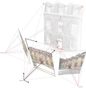
make it up, then the determination of the aspect of its surfaces. The developed tool presented here is an element of a complete approach for 3D surface reconstruction. This approach is founded on a hybrid registration of two types of digitalized sources (point-clouds and digital images) in order to provide a complete support for the 3D modelling process (Fig.8). It includes three distinct concerns: the first one is the surveying of the object under these metric and photometric points of views. The second one is the construction of its geometrical model and its enrichment by photometrical and dimensional information. The last one is the semantic organization (i.e. structuration) of the building.
For each concern, the approach introduces the architectural knowledge and its exploitation as a support to interpret and reproduce shapes. Combining range-based and image-based techniques, the surface reconstruction process uses: the 3D point-clouds to extract relevant profiles and to create triangulated-mesh; the digital images to cover shadow areas in the 3D point-clouds, to recover additional coordinates and to extract textures for their future mapping.
Figure 8: hybrid registration of point-clouds and digital images
In the modelling module, 3D point-clouds and digital images constitute respectively the metric and the visual (i.e. graphic) support [10]. The knowledge-based modelling module presented here allows the surface reconstruction focusing on relevant profiles
and using a library of architectural feature shapes in order to produce semantic representations of architectural elements and to organize them into hierarchical structures. The next section describes the knowledge formalisation process proposed. Section 3.2 presents the architectural feature shape library developed and the section 3.3 illustrates the feature instantiation process using dimensional information extracted from the digitized data of a real object.
3.1 Knowledge formalisation process
Based on an interpretative study of documentary sources or on a comparative analysis of different real elements, the formalization of an architectural element starts by the definition of the relevant shape profiles. A network of B-Splines curves associated with a modelling procedure is defined and constitutes the geometrical description level of the architectural element.
The method proposed to formalize the architectural primitives starts from an analysis of historical sources such as, for example, a simple frontage element (Fig. 9).
Figure 9: extract of an architectural treaty of the five classical orders
The (MEL) Maya Embedded Language’s core uses a data flow paradigm [11]. This core is incorporated in the dependency graph (DG). The data and their operations are encapsulated in the DG as nodes. In order to perform some complex modification to some data, a network of simple nodes is created. Each node has one or more properties associated with it. These properties are commonly defined as attributes. An entire geometric mesh or Non-Uniform
Rational B-Splines (NURBS) surface can be stored as an attribute in a node.
Thus, the first level of primitives is defined as set of simple nodes: the mouldings in our simple frontage example (Fig.10). Each node contains the essential attributes according with the entity position, the orientation of its centre point, plus its width and height.
These nodes are connected to children nodes defining the geometrical representation of the entities using B-Splines curves of different degrees. Five types of first level primitives are presented below.
Figure 10: a set of mouldings
In the same manner, a set of extrusion paths which drives the surface generation is defined. By connecting simple nodes, a chain of computation can be created to produce the final result [11].
To set up the concept of hierarchy, a Direct Acyclic Graph (DAG) is used. The DAG describes a hierarchy in which a node can not be both a parent and a child in the same lineage. The second level of primitives represents profiles defined by progressive combination of several first level primitives (Fig.11).
Figure 11: a combined profile: the second level of primitives
A constraint node links the last curve’s control point to the last one of the precedent entity. Thus, in the DAG paths, the relationship between a 3D object local reference (x, y, z) and a 2D (u, v) parametric space is known. This property is used to generate surfaces by creating a connection between a profile node, a modelling function and a path node. Each first level primitive of a profile node is extruded
along the parametric space of the associated path node (Fig.12).
Figure 12: example of an extrusion node In the same manner, but in an upper hierarchical level, the third level of primitives is created using Boolean operations (Fig.13).
Figure 13: Boolean operations applied to two extruded surfaces
The DG is based on a push-pull model. So, when one pull information from a node, it propagates that request through all the nodes that provide input connections to the node (Fig.14).
Figure 14: hierarchical organization of the formalized entities
3.2 Architectural feature library
A MEL command makes it possible to introduce a Web browser inside an interface layout. This browser allows receiving MEL script since a distant site. A simple script can contain the procedure for the surface generation, the parameter setting and the
structuration of a formalized entity. One of the fundamental properties of NURBS surfaces allows a deformation process to produce a shape which respect the parameters defined. This property is used to locate the primitive into the 3D space containing the 3D point-clouds and to adapt it precisely to the real shape of the digitized object. Such an instantiation process opens an interesting way around the structuration of a library of architectural entities taking again the treaties of architecture of different periods, whose described elements are translated into parametric modelling terms. The procedure developed to reconstruct architectural elements using an instantiation process based on a feature shape library is divided into three steps:
• Selection and generation of an architectural feature shape since a distant site,
• Fast positioning in the 3D point-cloud, • Dimensional adaptation of the surface
to the 3D point-cloud.
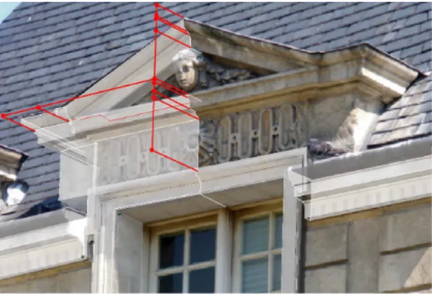
Imported once, the feature template is introduced automatically into the 3D scene and assigned at the geometric centre of a group of cameras with orthogonal projection. Then the user can locate the feature on different distinct windows (also including a calibrated image as show in Fig.15). The camera planes are located at centre of each relevant profile of the primitive. A device of “deformation tools” allows applying transformations (i.e. translation, orientation and scale factor) to the feature parameters. Transformations can be applied to an entire profile, to a single profile’s module or to a simple parametric control point.
Figure 15: illustration of the feature positioning step using a 3D handler
The constraint set encapsulated in the feature template produces a propagation of the deformations applied, to keep the coherence of the overall entity shape according with the architectural rules involved.
3.3 Extraction of dimensional information
One of the most interesting exploitation of the knowledge-based modelling tool consists in the possibility of creating, at the same moment of the positioning of the feature shape, an organized structure of drifting measurement. This is possible extracting the dimensional values associated the parameters of the primitives instanced. Modelling by architectural primitives becomes in this direction a way to structuring an organized abacus of dimensional information (Fig.16). We work actually to the management of these information in relational databases.
Figure 16: extraction of dimensional information To allow the future handling of the 3D building digital mock-up, the approach proposed ensures the structuration of the model of the architectural object in parts and sub-parts, and the identification of their reciprocal relations to guarantee a correspondence between the topological description model of the architectural object and its 3D geometrical representation. This aspect is very important in the objective of a semantic structuration of the elements which compose the scene for 3D real-time visualization as presented below.
4. Semantic 3D representation for
information interfacing
In the “3D Architectural Information System” (Sia3D) prototype [12] developed to illustrates the approach proposed on the basis of the remains of the Roman Theatre in Arles (in the south of France), the issue of how to better exploit, in terms of readability for architects, the results of a surveying process based on an image-based modelling techniques is
addressed. According with the principles established in [13], we consider it is necessary to identify and organise non-ambiguous morphological elements to which we will attach various information, including raw results of the surveying campaigns.
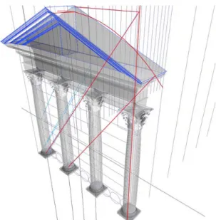
Figure 17: remains relocated in the space of their corresponding theoretical elements The results of the surveying and modelling process can be contextualized in the following way:
• by locating in a same reference space of both the elements surveyed and the theoretical elements (Fig.17),
• by positioning them with regards to their associated knowledge.
For example, once surveyed, a cornice’s remain can be displayed in a 3D model of the whole building with indications concerning:
• its belonging to an object typology (i.e. a stylistic references, a role in the building),
• its hypothetical position, marked as such, in the virtual building reconstruction,
To illustrate the previous contextualization concept, the following part of this section focuses on the final output structure of a 3D interpretative model of a Roman Theatre.
Figure 18: the theoretical model of a Roman Theatre in the Augustinian period
The surveyed remains are localised in the reference space of a theoretical Roman Theatre defined through the relevant architectural vocabulary previously analysed. The analysis made aims at identifying non-ambiguous concepts that on one hand correspond to physical objects which exist in the building (base, capital, …) and, on the other hand, have a significant role in the edifice’s composition. The vocabulary produced is used to rebuild, level after level, the theoretical model of a Roman Theatre in the Augustinian period (Fig.18). These levels can be read as rebuilding point of view starting by individual elements such as a capital to whole groups such as colonnade. Thus the levels defined match the concept of architectural scales.
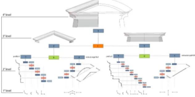
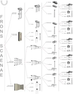
The building is thus described by a hierarchical structure that derives form the vocabulary analysis (Fig.19). The hierarchical structure formalizes as composition links the relations between the elements in a five (for the case of a Roman Theatre) level hierarchy (example: capital / part-of / column / part-of / colonnade / part-of / …). Once the elements are classified as shown above, and once the compositional rules are expressed, the understanding of the edifice is improved. The hierarchical structure also allows establishing bilateral relations between the information sources and the 3D model. Indeed, to each hierarchical level
specific information sources are associated. Thus, each element of the hierarchy acts as a filter in the handling of the 3D model since it is represented by its own geometry or by sub-elements.
Figure 19: the five-level hierarchical structuration of the architectural elements of a
Roman Theatre
The hierarchical structure controls transitions between levels, either inside the 3D scenes where geometrical representations of objects are grouped according with the level displayed, and also inside the information sheets. These information sheets gather data pieces on theoretical elements, but also descriptions of the surveyed remains (current localisation, conservation state, materials).
The 3D model is finally a digital mock-up of the building with an interface that allows the user:
• to select an element by its name in the hierarchical structure and to display its position in the scene,
• to get the information sheets related to this element,
• to select an element into the 3D model itself and to visualize its position in the hierarchical structure,
• to switch between levels according with the user requirements,
• to show / hide elements or groups of elements,
• to interactively control transparency level of selected elements or groups of elements,
• to show / hide selected remains, and so one.
Figure 20: illustration of the web interface developed in the Sia3D prototype
The interface developed (Fig.20) is accessible on a standard Web browser with the Virtools plug-in to read the 3D scene. Scene/windows interactions are written in JavaScript, enabling easy updating of the various links implemented. Indeed, a wide variety of information sheets links can be implemented such as surveying results or purely bibliographic sources.
5. Conclusion
An interesting development prospect relates to the problem of the multi-representation. Indeed, the proposed approach allows introducing the concept of objective or point of view, which governs the choices between various representations of the same object (i.e. multi-representation). These various representations will be able to correspond at various levels of consultation and necessary comprehension according to the user profiles. Moreover, the geometrical model associated with the object must also be able to take into account the temporal dimension of the building
(i.e. its evolution in the time). Within this framework, the 3D structured representation of buildings becomes a privileged support for real-time handling and to interact with the associated documentary sources (i.e. search and consultation of documents or information). These information and documents will be of course associated with the geometrical model of the object in a structured way and according to various user points of views (i.e. architects, historians, archaeologists, general public, and so one).
Acknowledgements
We thank MENSI Company for helpful comments; Prof. Alberto Sdegno of IUAV for the survey of “Convento della Carità” in Venice; the “Musée de l’Arles et de la Provence Antiques” for providing us documentary sources; Francesca De Domenico for providing us images from her implementation work (Fig.17,18,19,20).
References
[1] D. Barber, J. Mills, P. Bryan. Laser Scanning and Photogrammetry: 21st century metrology. CIPA Symposium, Potsdam, Germany 2001.
[2] C. Trevisan. Proporzioni e vera forma di particolari architettonici rilevati con scanner 3D: caratteristiche di un software specifico. in Disegnare idee immagini, 24 (2002), pp. 44-49.
[3] B. Curless, M. Levoy. A volumetric method for building complex models from range images. Proceedings SIGGRAPH96. [4] R. Migliari. Per una teoria del rilievo
architettonico; primi appunti. Website: http://www.rappresentazione.net
[5] M. Docci, R. Migliari. Geometria e Architettura. Gangemi Editore. Roma 2000 [6] A. Tzonis, L. Lefaivre. Classical
Architecture - The poetics of Order. MIT Press. Cambridge 1986
[7] A. Palladio. The four books of Architecture. Dover publications, New York 1965 (original: Venezia 1570)
[8] J.M. Perouse de Monclos. Architecture vocabulaire. Principes d’une analyse scientifique. Imprimerie Nationale, Paris 1988
[9] Vitruvius Pollio. Ten books on architecture. Cambridge University Press, 2001
[10] J-Y. Blaise, L. De Luca, M. Florenzano. Architectural surveying - from a point cloud to a 3D model. EVA2004 -Electronic Imaging and the Visual Arts. Florence 2004
[11] D. Gould. Complete Maya Programming: An extensive guide to MEL and C++API. Morgan Kaufmann, Paperback, 2002.
[12] J-Y. Blaise, F. De Domenico, L. De Luca, I. Dudek. Architectural Modelling and Information Interfacing: Learning from Three Case Studies. ITI 2004 - 26th International Conference on Information Technology Interfaces. Cavtat / Dubrovnik, 2004
[13] I. Dudek, J-Y. Blaise. New experimentation of a generic framework for architectural heritage data visualisation. ProceedingWSCG 2003, pp109-117.